Assembling
Default UI Menu: Modify/Modify 3D Objects/3D Assemble
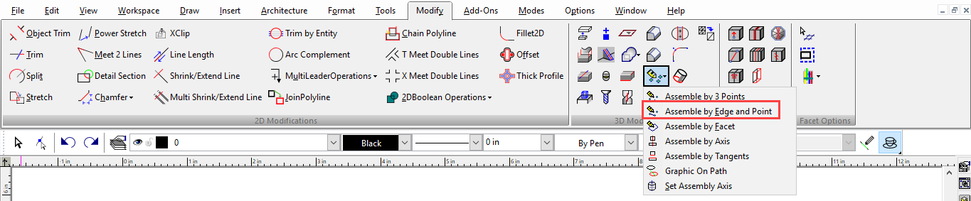
Ribbon UI Menu:
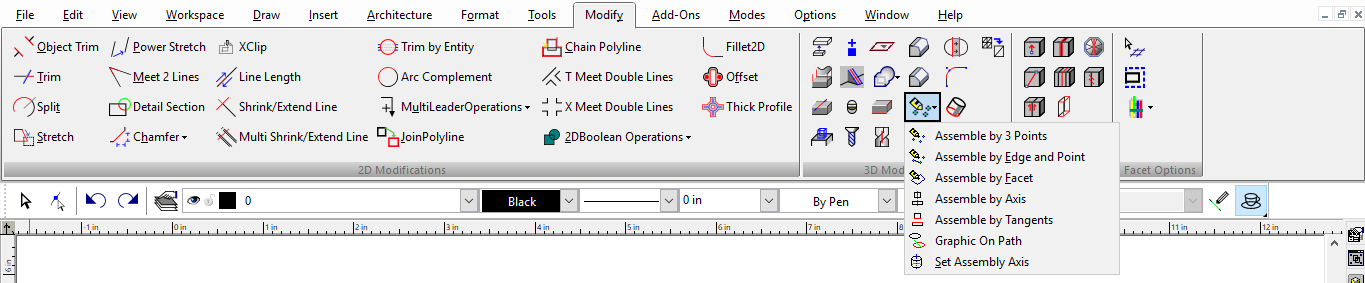
The Assemble tools are used to position a 2D or 3D object relative to another object.
The Assemble tools can be used on 2D and 3D objects. For the objects you want to use, be sure the Selector is set correctly (2D, 3D, or both). These tools are available on the 3D Modify toolbar, which you can display by right-clicking in any toolbar area and selecting 3D Modify.

Note: The Transform tools also enable you to move objects, as well as scale and copy, and do not require information as accurate as that required by the Assemble tools. In addition, you can record Transform operations for use on other objects.
Assemble by 3 Points

(Available in Platinum, Professional and Deluxe)
Default UI Menu: Modify/Modify 3D Objects/3D Assemble/Assemble by 3 Points
Ribbon UI Menu:
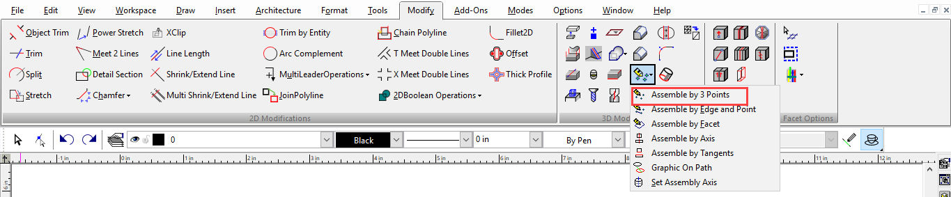
Changes the position of an object by changing the location of one point, two points (line), or three points (plane). The source points typically lie on the object to be moved, although this is not required. Destination points can lie on destination objects, or they can be specified in the Coordinate Fields. To assemble by one point:
- Select the object to be repositioned.
- Select the source point.
- Select the destination point.
- Select Finish from the local menu or Inspector Bar. The object is moved so that its source point meets the destination point, keeping its orientation.
To assemble by two points (line):
- Select the object to be repositioned.
- Select the first source point and its destination. This first set of points determines the actual object position; the remaining points set the orientation.
- Select the second source point and its destination.
- Select Finish from the local menu or Inspector Bar. The object is moved so that its first source point meets the first destination point, and the line between source points becomes aligned with the line between destination points.
Note: For another way to assemble by edges
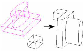
To assemble by three points (plane):
- Select the object to be repositioned.
- Select the first source point and its destination. This first set of points determines the actual object position; the remaining points set the orientation.
- Select the second source point and its destination.
- Select the third source point and its destination.
The object is moved so that its first source point meets the first destination point, and the plane defined by the source points becomes aligned with the plane defined by the destination points.
Note: In a particular case, just after two clicks "finish" is enabled in local menu. But in common case you can repeat 2 point selection 3 times: 6 clicks. So you can achieve any position of the object in space
Assemble by Edge and Point

(Available in Platinum, Pofessional and Deluxe)
Default UI Menu: Modify/Modify 3D Objects/3D Assemble/Assemble by Edge and Point
Ribbon UI Menu:
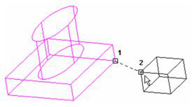
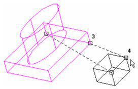
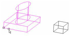
Changes the position of an object by changing the location and alignment of an edge. You can also add a source point and destination point to change the rotation as well. To assemble by a pair of edges:
- Select the object to be repositioned.
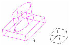
- Select the source edge. The new alignment of the edge depends on where you select the edge; the point you select will be moved to the point you select on the destination edge.
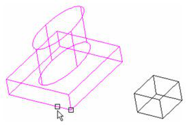
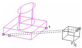
- Select the destination edge. The dotted lines indicate how the object will be aligned.
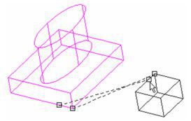
- Select Finish from the local menu or Inspector Bar. The object is moved so that its source edge meets the destination edge, connected at the two selected points.
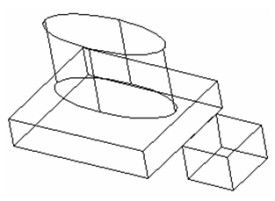
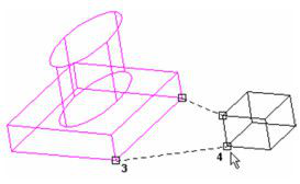
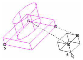
To assemble by edges and a plane:
- Select the object to be repositioned.
- Select the source edge. The new alignment of the edge depends on where you select the edge; the point you select will be moved to the point you select on the destination edge.
- Select the destination edge. The dotted lines indicate how the object will be aligned.

- Select a point on the source plane (not on the selected edge) and a point on the destination plane.
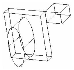
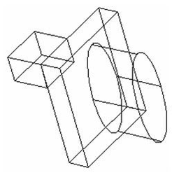
The object is moved so that its source edge meets the destination edge, connected at the two selected points. The rotation is set by the points on the source and destination planes. The results are shown here in Hidden Line render mode.
Assemble by Facet
(Available in Platinum, Professional and Deluxe)
Default UI Menu: Modify/Modify 3D Objects/3D Assemble/Assemble by Facet
Ribbon UI Menu:
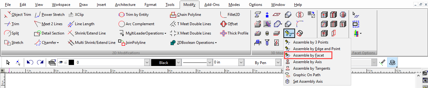
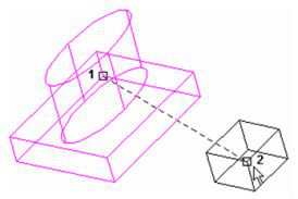
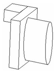
Changes the position of an object by aligning facets.
- Select the source facet of the object to be repositioned. To select a facet behind or in front of the indicated facet, you can use the Page Up and Page Down keys.
 |
|
- Select the destination facet.
The object is moved so that the source facet meets the destination facet. The results are shown here in Hidden Line render mode.
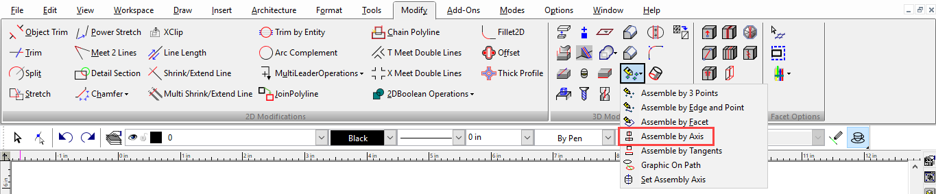
Assemble by Axis
(Available only in Platinum)
Default UI Menu: Modify/Modify 3D Objects/3D Assemble/Assemble by Axis
Ribbon UI Menu:
Changes the position of an object by aligning axes.
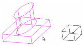
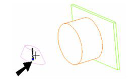
Assembling Circular or Rotated Objects
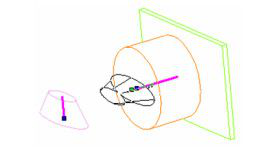
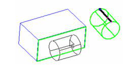
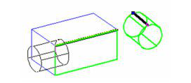
For round objects that have a rotational axis (such as Cylinder, Cone, Polygonal Prism, Revolve, or Simple Extrude based on a circular 2D object), you need to set the assembly axis before the objects can be assembled. This example will assemble a truncated cone based on an ellipse, aligning it with the axis of a cylinder.
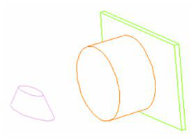
- Activate Set Assembly Axis.
- Click one of the round objects (the truncated cone, in this case). Its axis is displayed as a dashed line.
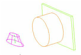
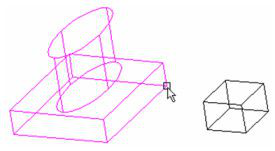
- Click the axis to define it for the assembly.
- Select Finish from the Inspector Bar or local menu.
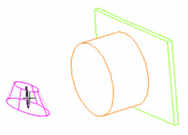
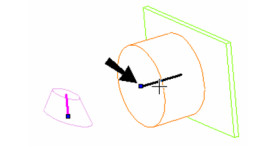
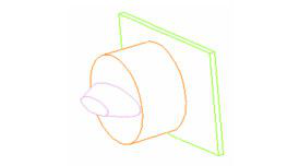
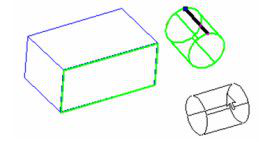
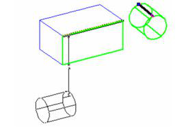
- Do the same to define the axis for the other round object (the cylinder).
- Select Finish from the Inspector Bar or local menu.
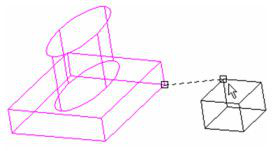
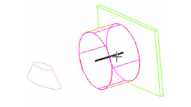
- Activate Assemble by Axis. Click the axis of the object you want to move. Be sure to select the axis near the endpoint that will meet the endpoint of the other axis.
- Click the destination axis, near the endpoint where the other axis will meet it.
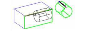
A preview of the moved object appears. You can move it in either direction along the axis.
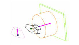
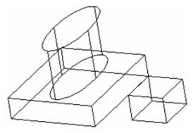
- Use the mouse or enter the move distance. If you want to rotate the object, you can enter an Angle. If the moved object is oriented backward, select Turn Over from the local menu or Inspector Bar.
- To rotate it with the mouse, select Rotate. If you turned or rotated the object, the preview will update.
- When the distance and angle are defined, the object moves so that the two axes are aligned.
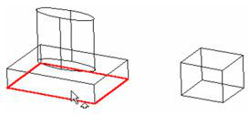
Assembling Planar or Linear Objects
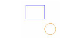
For objects that have no assembly axis defined, you can define the axis during the assembly process. This example uses a polygonal prism and a box.
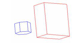
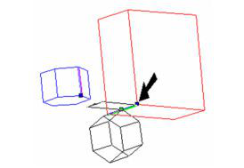
- Activate Assemble By Axis, and select Use Any Line from the local menu or Inspector Bar.

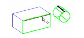
- Select the object you want to move. Then click a line or edge you want to use as the assembly axis. Be sure to click near the endpoint of the axis which will meet the other axis.
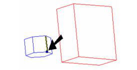
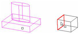
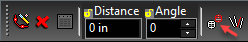
- Click an edge or line as the destination axis. Select it near the endpoint that will meet the other axis. A preview of the moved object appears. You can move it in either direction along the axis.
- Use the mouse or enter the move distance. If you want to rotate the object, you can enter an Angle. If the moved object is oriented backward, select Turn Over from the local menu or Inspector Bar.
- To rotate it with the mouse, select Rotate. If you turned or rotated the object, the preview will update.
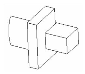
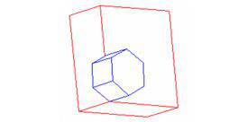
- When the distance and angle are defined, the object moves so that the two axes are aligned.
Distance by faces, Angle by faces and Angle by axes
Make sure to create sufficient axes to setup for these modes. Make two axes of two bodies coincident, then select one of modes by using hot keys or local menu
Distance by Faces
- Select the Distance by faces mode.
- Define the first face on the body which will be moved.
- Define destination face
- The body will be moved by the distance between selected faces along the common axis and two faces will become coincident.
Angle by Faces
- Select face on body you want to rotate.
- Select the second face (on any body) you wish the first face to to be parallel to.
- If the rotation around the common axis is available, then the normals of the two defined faces will become coincident/parallel.
Angle by Axes
Mode 1:
- Select the second axis on first body; the one you are moving.
- Select the second axis on the body you are aligning to.
- If the rotation around the common axis is available, the directions of selected axes will become coincident.
Mode 2:
- Select the second axis on first body; the one you are moving.
- Select the second axis on the body you are aligning to.
- If the rotation around the common axis is available, the directions of selected axes will become coincident.
Assemble by Tangents
(Available only in Platinum)
Default UI Menu: Modify/Modify 3D Objects/3D Assemble/Assemble by Tangents
Ribbon UI Menu:
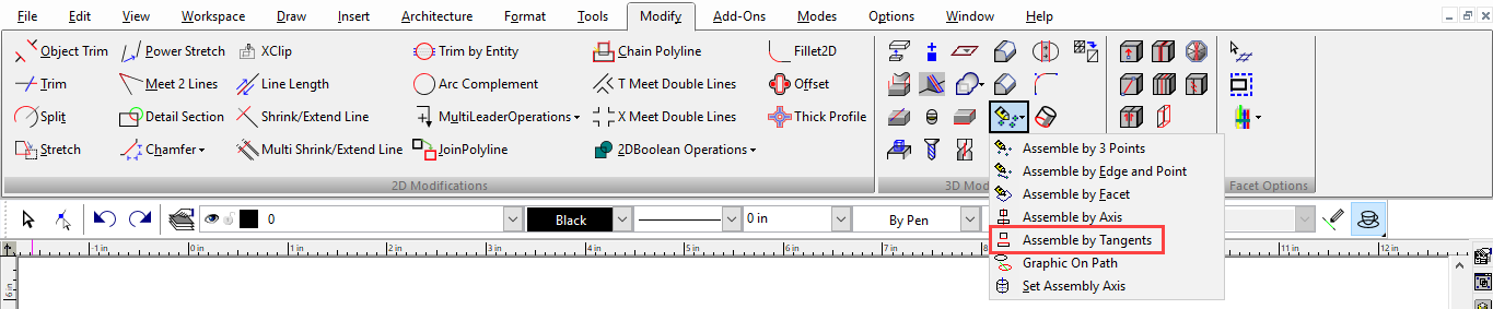
Changes the position of an object by aligning a cylindrical face tangent to another cylindrical face, or to a flat face. This example will assemble a cylinder and a box.
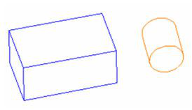
Aligning to a Face
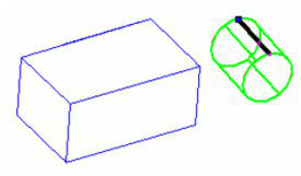
- Activate Assemble by Tangents. Select the object that will move (the cylinder). Be sure to select the axis where you want the object to be placed on the second object.
- To align the object to a face, and not to a specific axis or point, click the face of the second object. This face can be planar or cylindrical. Where you click defines the initial location of the first object.
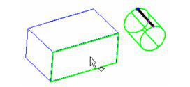
A preview of the moved object appears.
- You can move the preview anywhere, and it remains tangent to the face.
- When you place the object, and view it in Side view. you can see that the cylinder is tangent to the face of the box.
Aligning to a Face and Edge
- You can align a cylindrical face to both a face and edge. When selecting the second face, click on one of its edges.
The preview shows the cylinder aligned to both the face and edge.
- A Distance to Edge value will move the cylinder away from the edge, in an offset direction while staying tangent to the face.
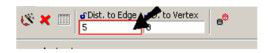
- A Distance to Vertex value will move the cylinder along the edge.

- When you place the object, and view it in Side view. you can see that the cylinder is tangent to the face and edge of the box.