Opening and Saving Files
Within TurboCAD you can choose to open a saved file or start a new file. You can also open new and saved files from within TurboCAD, and there are several options for saving files.
Note: The General page of the Program Setup contains several settings for opening and saving files.
Opening Files
Default UI Menu: File/Open
Ribbon UI Menu:
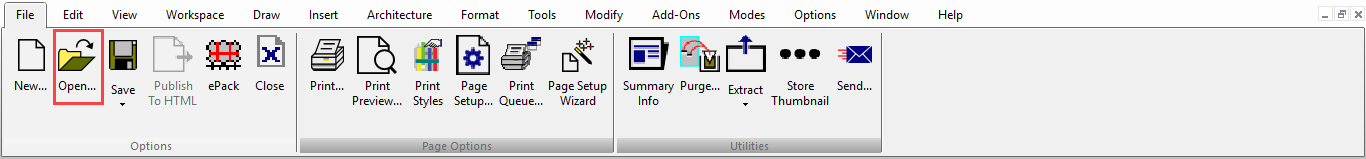
Hotkey: Ctrl+O
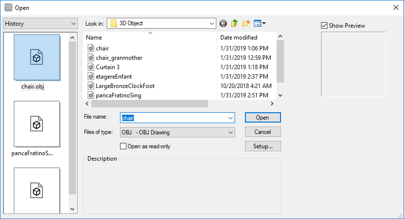
Files of type: By default, you will open a .tcw file. Use this list if you want to open a file of a different format. Open as read-only: A read-only file can be viewed only; it cannot be edited. Description: Displays text entered in the Subject field of the Summary Info window. Show Preview: Displays a thumbnail of the drawing. Only TurboCAD files (.tcw and *.tct) can display previews. Setup: When importing files of other formats, provides access to conversion options.
Note: You can select multiple files from the file window to open at the same time. Simply hold down the Shift key to select multiple files.
Purge
Default UI Menu: File/Drawing Utilities/Purge
Ribbon UI Menu:
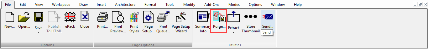
The purge tool is designed to make your files smaller by eliminating un-used elements that are stored in your file. For example, you can purge un-used blocks, line styles, or object styles.
- Select File | Drawing Utilities | Purge. The Purge dialog will open.
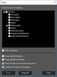
  2. Select the items you wish to purge. If necessary expand the tree so you can select sub-items. Alternately you can press the Purge All button.

  3. After selecting your items to press the Purge button.

  4. Press Close when you are finished.
Purge Options
Show Used Items- When this option is selected the tree will show the items in the tree. You cannot purge while this option is on. Selecting items in the tree will show purge parameters for that item type. The parameters are displayed in a text box directly below this option checkbox.
Purge default linestyles: If this option is turned on un-used default linestyles will be purged from the drawing. This option is off by de fu alt. It is recommended to use this option with caution.
Purge default brushstyles: If this option is turned on un-used default brushtyles will be purged from the drawing. This option is off by default, it is recommended to use this option with caution.
Clear all undo records before action: If this option is turned on all undo buffers will be deleted. This prevents issues with an attempt to undo purged items. This option is on by default.
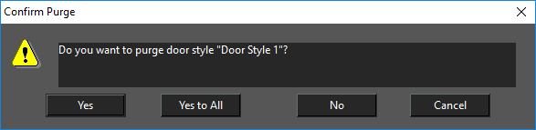
Confirm each item to be purged: If this option is on you will be presented will a confirmation dialog for each item that is being purged from the drawing. This option is on by default.
Saving Files
Default UI Menu: File/Save
Ribbon UI Menu:
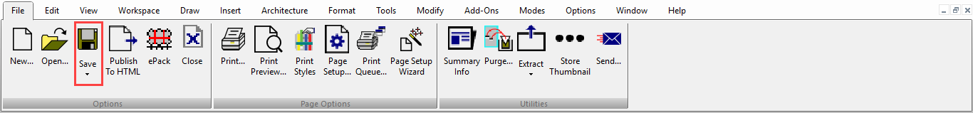
Hotkey: Ctrl+S
Saves the current drawing to disk. If the file was not previously saved, the Save As window will appear.
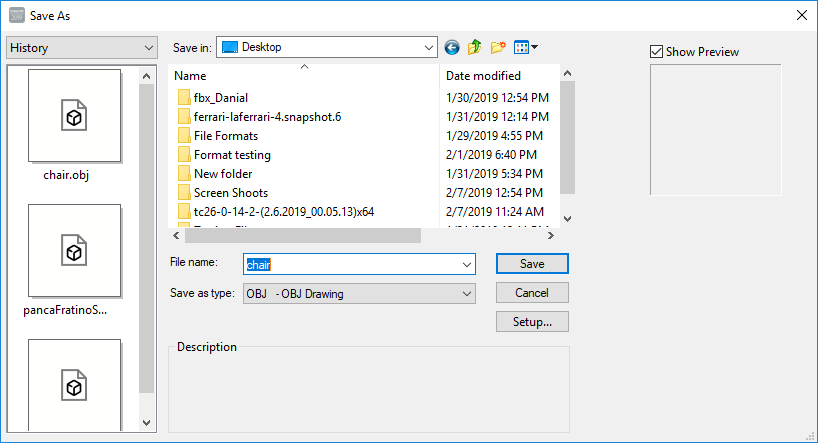
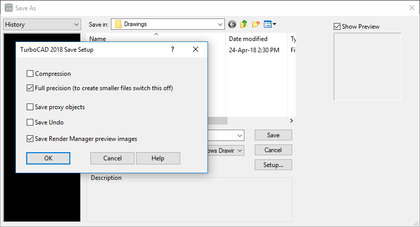
Save as type: By default, you will save the file as a .tcw file. Use this list if you want to save (export) the file to a different format. Setup: Enables you to set parameters for the saved .tcs file. When exporting to another file format, provides access to conversion options.
Save:
Drawing: Saves the entire drawing. Selection: Saves the selected objects only. IfPrompt for Summary Info is checked in the General page of the Program Setup, the Summary Info window will appear before saving.
Tile Area
TurboCAD splits a large image into pieces (horizontal stripes) in order to save memory while rendering, and then stitches these fragments into a single image.
The filter settings dialog bitmap (bmp, jpg, gif, png) now contains an option called Tile Area, which allows users (based on the amount of memory) to establish the image fragmentation settings
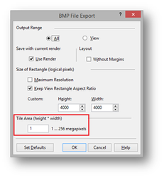 Minimal (default) value – 1 megapixel, corresponds to the image size of 1000 x 1000.
Maximal value – 256 megapixels, corresponds to the image size of 16000 x 16000 (maximum resolution).
If you set"Tile Area" = 256, then for any size of image, fragmentation will not work.
Minimal (default) value – 1 megapixel, corresponds to the image size of 1000 x 1000.
Maximal value – 256 megapixels, corresponds to the image size of 16000 x 16000 (maximum resolution).
If you set"Tile Area" = 256, then for any size of image, fragmentation will not work.
Please note: When installing large values "Tile Area" is very likely to be used throughout the computer's memory which can lead to system instability.
Undo/Redo File Buffer
With this Save file option, the Undo/Redo buffer of a file is saved when the file is closed or when the application closes. The buffer is re-loaded when the file is reopened and can be used from the last point. Some operations are not saved within the Undo/Redo buffer.
Summary Info
Records general information to be saved with the drawing.
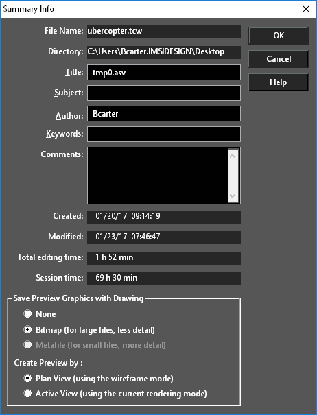
If Prompt for Summary Info is checked in the General page of the Program Setup, the Summary Info window will appear when you save the drawing. File Name and Directory: Information for files that have already been saved. Keywords: Text used when searching for this file. Subject: Descriptive text that appears in the Open and Save windows. This text can also potentially be used by Windows file search utilities.
Tip: If a drawing is being saved as a symbol, the Title should be a short description of the symbol, and Subject contains a more detailed description.
Save Preview Graphics with Drawing: Sets the type of graphic image that will be stored with the drawing, so that it can be previewed in TurboCAD and in other Windows programs. None: No preview graphics will be saved. Bitmap: Suitable for large files because the bitmap will use the same amount of space no matter how complex the drawing is. Metafile: Suitable for small files because it displays more detail. Symbol previews are generally stored using this option. Create Preview by: Saves the preview as the plan view or by the current view and render mode.
Time Stamp
The time stamp feature adds system information about the date/time of drawing creation, the date/time of the last modification, total time spent editing the drawing and the total time of the last editing session.
The information is available in "Summary Info" dialog (File | Summary Info...). The information is stored in the following file formats: TCW, DWG, DXF.
ePack
File|ePack
Default UI Menu: File/ePack
Ribbon UI Menu:
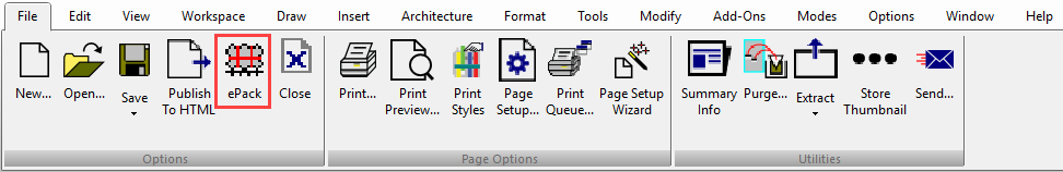
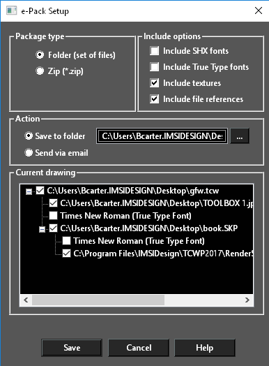
The ePack utility is designed to encapsulate in one location all the external files associated with a drawing. This includes Xrefs, material images, linked images, fonts, and other referenced files. Once activated you must specify the following:
-
Package type: This can be either a Folder of a Zip.
-
Include options:
You may choose to include or exclude:
- SHX fonts – a standard for DWG files
- True Type Fonts – Standard for Windows files.
- Textures – Images which are used to create materials
-
File References – Xrefs and all other referenced files
-
Action:
With two options:
- Save to folder – This is the location where the new folder or zip will be created.
- Send via email – the entire packet is sent by email to the designated parties.
Lastly, you may use the Current Drawing tree and specifically select/deselect items that you wish to be packed. When you click the Save button the folder or zip will be created and all files, including the drawing, will be packed.
IFC Export and BIM
 IFC stands for Industry Foundation Classes (IFC). This is a standard data model used to describe data for the building and construction industries
It is a platform-neutral, open file format specification commonly used collaboration format for Building information modeling (BIM).
The following Items are exported to IFC:
IFC stands for Industry Foundation Classes (IFC). This is a standard data model used to describe data for the building and construction industries
It is a platform-neutral, open file format specification commonly used collaboration format for Building information modeling (BIM).
The following Items are exported to IFC:
- Architectural objects
- Custom Properties
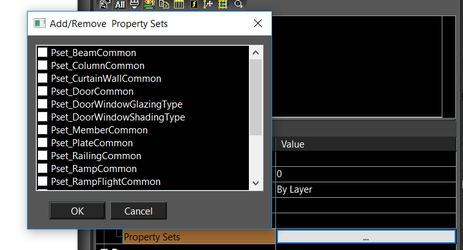
- Property Sets
The data is mapped as follows:
| TC Representation | IFC Element |
|---|---|
| IfcBooleanResult | |
| box | IfcBoundingBox |
| IfcManifoldSolidBrep | |
| sweep | IfcRevolvedAreaSolid |
| IfcSolidModel | |
| IfcSweptAreaSolid | |
| sweep | IfcSweptDiskSolid |
| line | IfcAxis1Placement |
| IfcBoundedCurve | |
| IfcConic | |
| IfcElementarySurface | |
| ellipse | IfcEllipse |
| IfcGeometricRepresentationItem | |
| IfcPlacement | |
| IfcPoint | |
| IfcRepresentationItem | |
| IfcNamedUnit | |
| IfcPresentationLayerAssignment | |
| IfcColourSpecification | |
| IfcSimpleProperty | |
| IfcGeometricRepresentationContext | |
| IfcGeometricRepresentationSubContext | |
| IfcRepresentationContext | |
| IfcShapeModel | |
| IfcStyleModel | |
| IfcLoop | |
| IfcTopologicalRepresentationItem | |
| group | IfcGroup |
| IfcObjectDefinition | |
| IfcPropertyDefinition | |
| IfcPropertySetDefinition | |
| IfcRoot | |
| IfcTypeObject | |
| IfcTypeProduct | |
| IfcBuildingStorey | |
| IfcElement | |
| wall | IfcCurtainWall |
| beam | IfcMember |
| slab | IfcPlate |
| railing | IfcRailing |
| slab | IfcRamp |
| slab | IfcRampFlight |
| stair | IfcStairFlight |
| IFC Object | TurboCAD Object |
| IfcBeam | Beam |
| IfcColumn | Column |
| IfcProject IfcSite IfcBuilding IfcBuildingStorey IfcPropertySet(Pset_ProjectCommon) IfcPropertySet(Pset_BuildingCommon) IfcPropertySet(Pset_BuildingStoreyCommon) | Drawing |
| IfcWallStandardCase | Wall |
| IfcMaterial | Wall style |
| IfcOpening IfcWindow | Window |
| IfcWindowLiningProperties IfcWindowPanelProperties IfcPropertySet(Pset_WindowCommon) IfcPropertySet(Pset_DoorWindowGlazingType) | Window style |
| IfcOpening IfcDoor | Door |
| IfcDoorLiningProperties IfcDoorPanelProperties IfcPropertySet(Pset_DoorCommon) IfcPropertySet(Pset_DoorWindowGlazingType) | Door style |
| IfcSlab | Slab |
| IfcMaterial | Slab style |
| IfcStair | Stair |
| IfcPropertySet(Pset_StairCommon) | Stair style |
| IfcRailing | Rail |
| IfcPropertySet(Pset_RailingCommon) | Rail style |
| IfcRoof | Roof |
| IfcMaterial | Roof style |
| IfcBuildingElementProxy | Landscape |
| IfcBuildingElementProxy | Other 3D objects |
| IfcPresentationLayerWithStyle | Layer |
| IfcPropertySet(TC_Pset_Custom) | Custom properties |
| IfcPropertySet(property set definition name ) | Property set |
IFC Import
IFC files can be imported. Geometry is converted to architectural objects where possible. Where not possible geometry is converted to grouped surfaces. To enable IFC Data
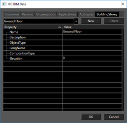
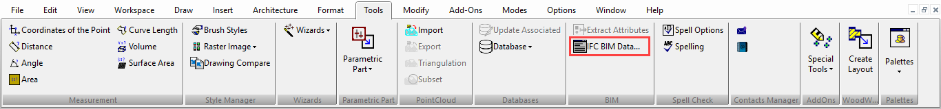
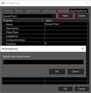
- Go to Tools and select IFC BIM Data. The IFC BIM Data dialog appears
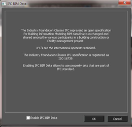
- Check the Enable IFC BIM data.
- Click OK.
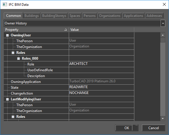
- This will open the IFC BIM Data dialog.
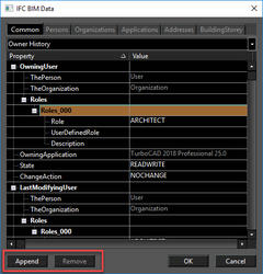
This dialog Allows you to view add or alter IFC BIM data as needed.
Following features are now available
- Common
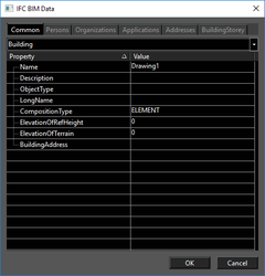
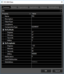
- Buildings
- BuildingStoreys
- Spaces
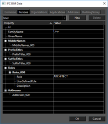
- Persons
- Organizations
- Applications
- Addresses
 Clicking on some fields will present a Drop-down list.
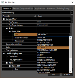 Clicking on some fields will give you the option to Append or Remove a duplicate of the field
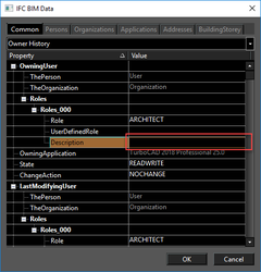
 Clicking on all other fields will allow you to enter data directly.
 The pages of the dialog are sorted using the tabs at the top, and the drop-down list below the tabs.
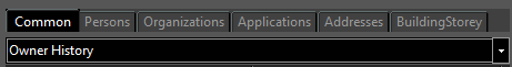 The Tabs are: Common, Persons, Organizations, Applications, Addresses. The contents of the drop-down alter depending on which tab is selected.
Here are all of the available pages:
The Tabs are: Common, Persons, Organizations, Applications, Addresses. The contents of the drop-down alter depending on which tab is selected.
Here are all of the available pages:
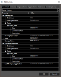
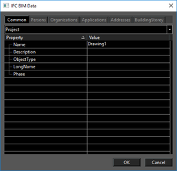
Common
Persons
Organizations
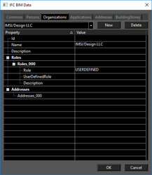
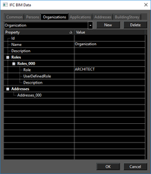
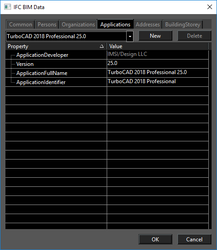
Applications
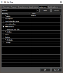
Addresses
Building Storey
Object Data
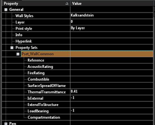
Non-geometric data is mapped to custom properties for standard IFC data, and to Property Sets for expanded AEC data.
| TC Representation | IFC Element |
|---|---|
| IfcBooleanResult | |
| Box | IfcBoundingBox |
| Set of curves | IfcGeometricCurveSet |
| Set of curves and surfaces | IfcGeometricSet |
| IfcManifoldSolidBrep | |
| Sweep | IfcRevolvedAreaSolid |
| IfcSolidModel | |
| Sweep | IfcSurfaceCurveSweptAreaSolid |
| IfcSweptAreaSolid | |
| Sweep | IfcSweptDiskSolid |
| Line | IfcAxis1Placement |
| IfcBoundedCurve | |
| IfcConic | |
| IfcElementarySurface | |
| Ellipse | IfcEllipse |
| IfcGeometricRepresentationItem | |
| IfcPlacement | |
| IfcPoint | |
| IfcRepresentationItem | |
| IfcNamedUnit | |
| Material | IfcSurfaceStyleRendering |
| IfcPresentationLayerAssignment | |
| IfcColourSpecification | |
| Curve | IfcArbitraryOpenProfileDef |
| Region | IfcArbitraryProfileDefWithVoids |
| IfcArbitraryClosedProfileDef | |
| Polyline | IfcAsymmetricIShapeProfileDef |
| Polyline | IfcCShapeProfileDef |
| Polyline | IfcCircleHollowProfileDef |
| Ellipse | IfcEllipseProfileDef |
| Polyline | IfcIShapeProfileDef |
| Polyline | IfcLShapeProfileDef |
| IfcParameterizedProfileDef | |
| IfcProfileDef | |
| Region | IfcRectangleHollowProfileDef |
| Polyline | IfcRoundedRectangleProfileDef |
| Polyline | IfcTShapeProfileDef |
| Polyline | IfcUShapeProfileDef |
| Polyline | IfcZShapeProfileDef |
| IfcSimpleProperty | |
| IfcGeometricRepresentationContext | |
| IfcGeometricRepresentationSubContext | |
| IfcRepresentationContext | |
| IfcShapeModel | |
| IfcStyleModel | |
| IfcLoop | |
| IfcTopologicalRepresentationItem | |
| Group | IfcGroup |
| IfcObjectDefinition | |
| IfcPropertyDefinition | |
| IfcPropertySetDefinition | |
| IfcRoot | |
| IfcTypeObject | |
| IfcTypeProduct | |
| IfcBuildingStorey | |
| IfcElement | |
| Wall | IfcCurtainWall |
| Beam | IfcMember |
| Slab | IfcPlate |
| Railing | IfcRailing |
| slab | IfcRamp |
| Slab | IfcRampFlight |
| Stair | IfcStairFlight |
IFC BIM Data and BIM Tool
(Available in Platinum)
Default UI Menu: Tools/IFC BIM Data
Ribbon UI Menu:
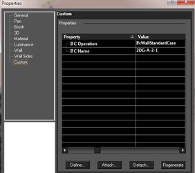
IFC stands for Industry Foundation Class, and these are the international standards for types of objects used in CAD software, design, and BIM (Building Information Management) software. By enabling IFC BIM data from an imported drawing, you can to use the property sets that are part of IFC standard. You can choose property set from the Selection Info palette, under the General option.
You can also set or retrieve data about the IFC file itself, including the creator and the owner of the file, and the organization associated with the creator.
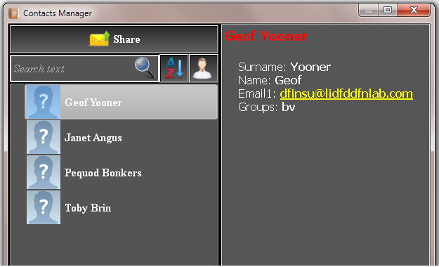
Contact Manager
Default UI Menu: File/Share/Run Contacts Manager
Ribbon UI Menu:
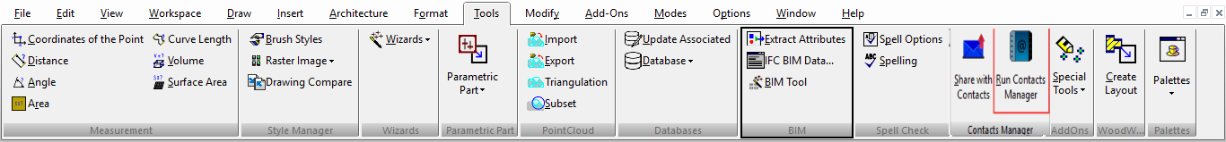
The Contact Manager is used to hold a list of contacts you can use to share your files with.
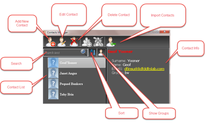
Add New Contact
Clicking the Add New Contact button opens the dialog.
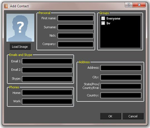
- Enter data into all of the relevant fields.
- Select the appropriate groups for the contact.
- If an image is an available click the Load Image button, navigate to the image, select it, then click OK.

- Click OK to finalize the Contact.
Edit Contact
Clicking the Edit Contact button opens the dialog for the currently selected contact.
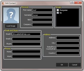
- Enter data into all of the relevant fields.
- Select the appropriate groups for the contact.
- If an image is available click the Load Image button, navigate to the image, select it, then click OK.
- Click OK to finalize the Contact editing.
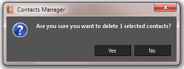
Delete Contacts
To delete a contact, select all of the contacts you wish to delete. Then click the Delete Contacts button. You will be prompted to confirm the deletion.
Click Yes to confirm the deletion.
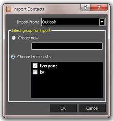
Import Contacts
Clicking the Edit Contact button opens the dialog for the currently selected contact.
Contact Info
This shows the information for the currently selected contact. If multiple contacts are selected it will show the last contact selected.
Contact List
This shows the list of all of your contacts.
Search
Searching is automatic. Just type into the Search field.
Once a search is entered you can clear it by clicking the X in the Search field.

Sort
This sorts the contact list into alphabetical order. If pressed again it will sort the list into inverse alphabetical order.
Show Groups
This flips the interface from Contact mode into Group mode.
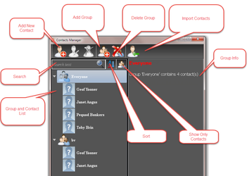
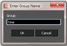
Add Group
Clicking the Edit Contact button opens the dialog for creating a group.
Type in a name for the Group and click OK.
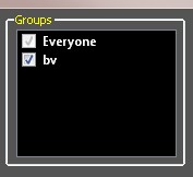
 To add a contact to a group, edit the contact and select the required group in the Groups list.
Delete Groups
To delete a contact, select all of the contacts you wish to delete. Then click the Delete Contacts button. You will be prompted to confirm the deletion.
Click Yes to confirm the deletion.
Import Contacts
Clicking the Edit Contact button opens the dialog for the currently selected contact.
Group/Contact Info
This shows the information for the currently selected group or contact. If multiple contacts are selected it will show the last contact selected.
Group and Contact List
This shows the list of all of your Groups and Contacts.
Search
Searching is automatic. Just type into the Search field.
Once a search is entered you can clear it by clicking the X in the Search field.
Sort
This sorts the contact list into alphabetical order. If pressed again it will sort the list into inverse alphabetical order.
Show Only Contacts
This flips the interface from Group mode into Contact mode.
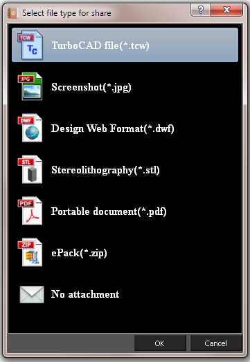
Share
Default UI Menu: File/Share/Share with Contacts
Ribbon UI Menu:
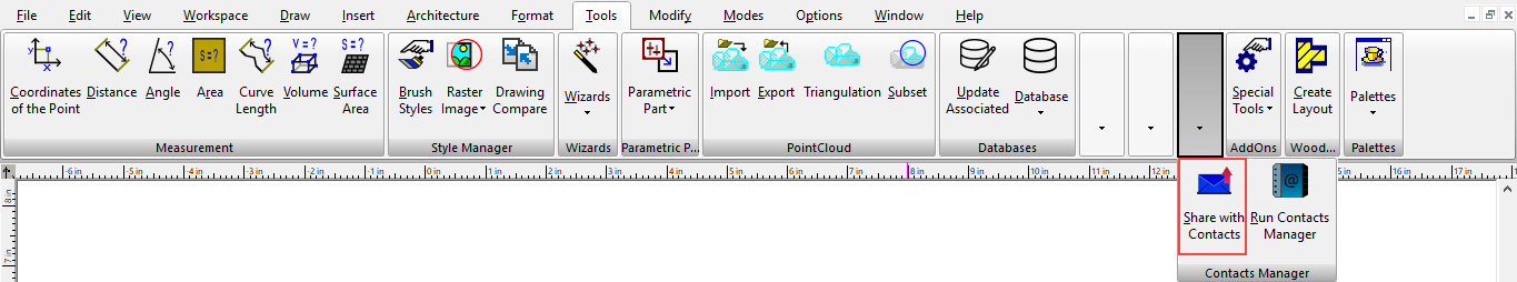
The Share tool uses the Contact manager to send your current file to your contacts.
 To share a file:
- Select the contacts that will receive the file.
- You will then be prompted for the manner in which the file will be sent: TCW - sends a standard TurboCAD file JPG - sends a screenshot image. DWF - sends a Design Web Format PDF - sends a Standard PDF version of the CAD file. ePack - Uses the ePack utility to zip up all the necessary components into ePack file. No Attachment - Sends an empty email to the designated contacts. This allows you to just send an email.
- Then click OK.