Viewports
(Available in all TurboCAD Variants)

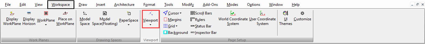
Default UI Menu: View/Viewports
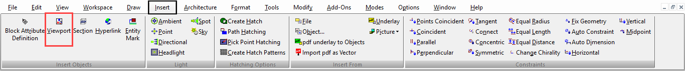
Ribbon UI Menu:
Viewports are used in Paper Space to display one or more views of your model. A viewport has two components: a boundary and the view that it contains. You can only insert views that have already been created -
Note: If you want to insert standard views (views you do not have to pre-define), Typically, multiple viewports are created so that you can show several view of the model. If you make changes to your model, any relevant views in the viewports will automatically update.
Once a viewport is created, you can use 2D tools and annotation tools (Text, Dimensions, Hatching, etc.) to enhance the Paper Space. You also have the option of saving a viewport's contents as an image. This is handy for rendering objects in viewports, because it is faster to display an image than to render an object.
Cache Properties
Options for storing images in viewports.
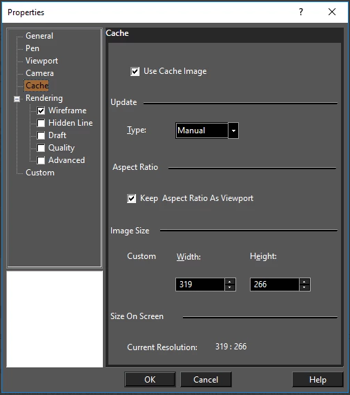
Use Cache Image: The viewport image will be stored as a picture, so that the image does not have to be regenerated. This is handy for large, rendered images that can take time to generate. Update: If Manual is selected, the generated picture will be updated after you select Update Viewport Cache. The remaining options on this page control the quality and size of the generated picture.
Exploding Viewports
(Available only in Platinum)
You can explode a viewport. Wireframe views and Hidden line views are turned into 2D entities. If the viewport is in a rendered (Draft, Quality, advanced) mode the result will be a 2D image.
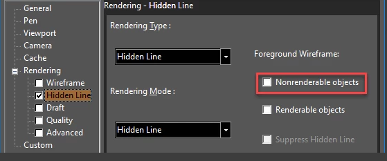 To work Non-Renderable objects must be turned off in the viewport rendering mode you have selected.
- Select the viewport.
- Click Explode.
Floating Model Space
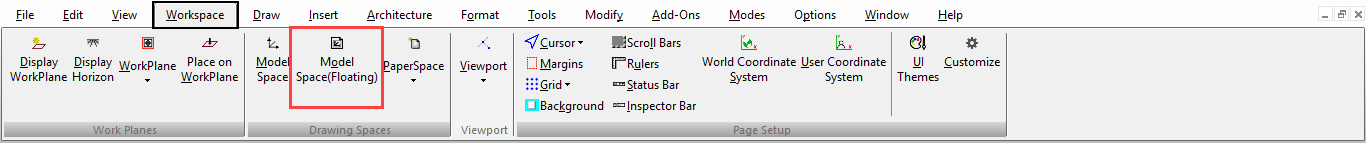
Default UI Menu: View/Viewports/Model Space(Floating), Modify/Model Space(Floating)
Ribbon UI Menu:
Enables you to use Model Space tools within a viewport in Paper Space. This is useful for making minor adjustments to your model within Paper Space, without having to switch to Model Space. Any substantial changes, however, should be done in Model Space.
- Select the viewport you want to use to edit the model.
- Select Model Space (Floating).
- The viewport is outlined in bold. You can now make minor edits using most of the Model Space tools.
- Click outside the viewport to finish editing and return to Paper Space.
Warning: If you rotate the view in a floating viewport, the view will not return to its original position when you return to Paper Space.
Inserting Viewports
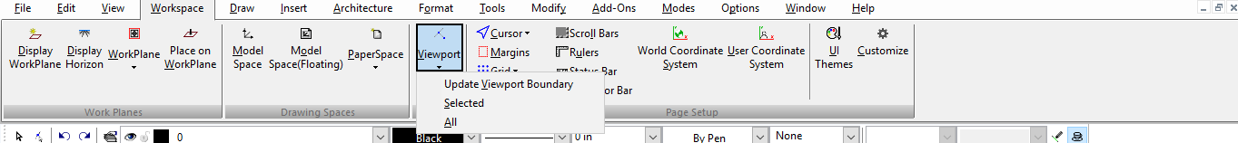
Default UI Menu: View/Viewports/Viewport
Ribbon UI Menu:
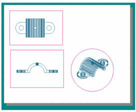
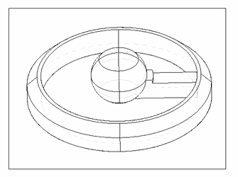
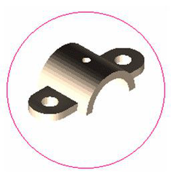
The following example will be used to demonstrate the use of viewports. To try it yourself, open the file clamp.tcw in the Samples\3D Samples folder.
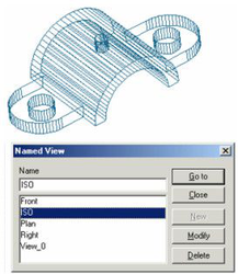
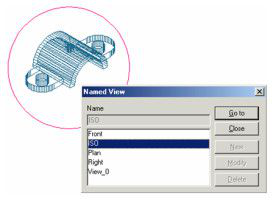
- Switch to Model Space, and select View / Named View. Several views have already been defined. (For details on named views, )
- There is already one Paper Space tab, containing several viewports. Right-click on the tab and select Insert to create a clean Paper Space.
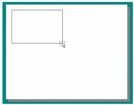
3.Select Insert / Viewport (or use the Insert Viewport icon) and define a rectangular boundary in one corner.
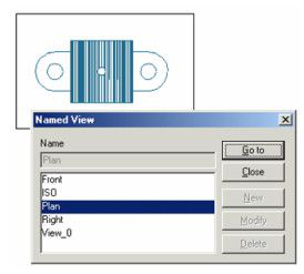
- In the Named View window, select the desired view (in this case, Plan). Clicking Go To will display the view without closing the window; this is a good way to check that the view is correct, If you double-click a named view, the view will fill the viewport and the window will close.
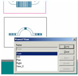
- Insert another viewport containing the Front view.
Once a viewport is created, the view inside it can be changed (as well as other parameters) by accessing its Properties.
Tip: If you want to create a viewport of the same size as an existing one, you can copy it . You can then open its Properties to select another view.
Local menu option:
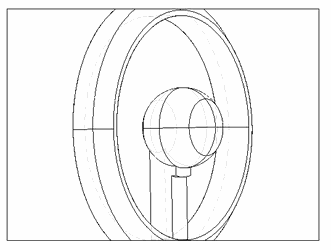
Shaped Viewport: Enables you to use any closed 2D object as the viewport boundary.
- In the Paper Space drawing sheet, use the 2D tools to create the closed boundary, in this case, a circle.
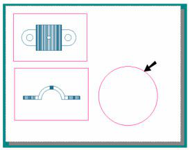
-
Activate Insert Viewport with the Shaped Viewport option. Select the closed boundary you just created.
-
Select a view as before, in this case, ISO.
Overlapping Viewports
Viewports behave like standard 2D objects, in terms of their stacking order and overlapping. You can adjust overlapping viewports using the Format menu (Bring to Front, Send to Back, etc.).
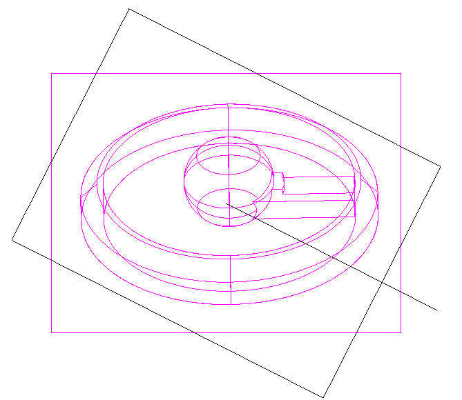
Rotate View with Viewport
You can rotate views by rotating the containing viewport.
First make sure that the Scale is Fixed in the Viewport properties.
 Select the viewport.
 Rotate the Viewport.
 The result is rotated content.
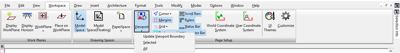
Update Viewport Boundary

Default UI Menu: View/Viewports/Update Viewport Boundary
Ribbon UI Menu:
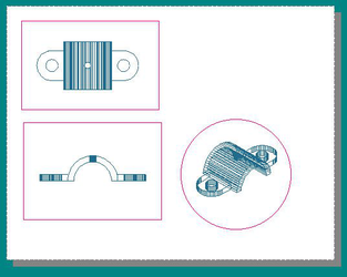
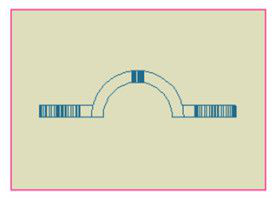
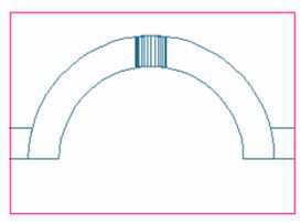
A viewport's boundaries can be replaced with any closed 2D object. This is useful in cases like the one shown below, in which the viewport on the right is partially hidden beneath the other two viewports.
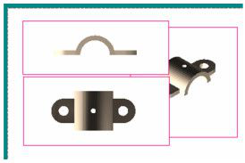
- Create the closed 2D object you want to use as the new boundary. In this case, the top left viewport boundary will be replaced with an ellipse.
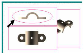
- Activate Update Viewport Boundary, and select the boundary to change. Then select the new boundary.
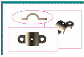
If the new boundary is too large or too small for the view inside, you can open the viewport Properties and change the Scale.
Tip: The conventional way to select the viewport is to click its boundary. It can sometimes be hard to select the viewport if its boundary is invisible. In this case, use F6 or F7 to scroll through the viewports.
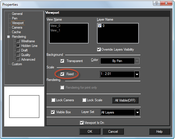
Viewport Properties
Options for the viewport appearance and the objects it contains.
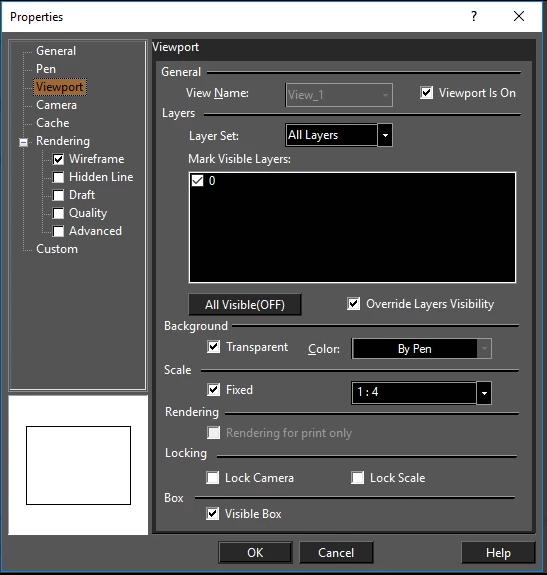 View Name: Shows all available views. You can use this list to select another view to fill the viewport.
Layer Name: Shows all drawing layers. You can check all layers you want displayed.
Override Layer Visibility: If this option is on the viewport ignores global layer visibility and uses its own set of visible layers. By default this property is on. But when an DWG/DXF is imported this property is set to "off".
Background: If Transparent is not used, you can set a color for the viewport background.
View Name: Shows all available views. You can use this list to select another view to fill the viewport.
Layer Name: Shows all drawing layers. You can check all layers you want displayed.
Override Layer Visibility: If this option is on the viewport ignores global layer visibility and uses its own set of visible layers. By default this property is on. But when an DWG/DXF is imported this property is set to "off".
Background: If Transparent is not used, you can set a color for the viewport background.
Scale: Sets the ratio of the viewing scale for the viewport. To set the scale, check the Fixed box and then select or enter the scale. The viewport boundaries do not change, so if the scale increases the view, it may extend past the boundaries.
Note: If dimensions are included in the viewport, the dimension is associative with the viewport. This means that the dimension is scaled simultaneously with the scaling of the viewport. To make the dimension non-associative, select both the viewport and the dimension and choose Drop link from the local menu.
Rendering: If you want the view inside a viewport to be rendered, check the desired render type on the left side of the Properties window.
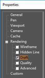
Note: If Hidden Line, Draft, or Quality mode is specified, you can explode the viewport. An exploded viewport becomes a Group of graphics or Picture object, which you can verify in the Selection Info Palette.
Rendering for print only: The rendered view appears only when printed, not on the screen. Lock Camera: Using Space Change through a viewport allows you to maneuver the view into model space by panning and turning. The Lock Camera setting causes the view to automatically return to the camera location and direction that were in place before using space change. Lock Scale: Using Space Change through a viewport allows you to maneuver the view into model space through zooming. The Lock Scale setting causes the view to automatically return to the zoom level and view scale that were in place before using space change. Visible Box: Displays or hides the viewport boundary line.
Tip: When a viewport's boundary is invisible, it can be hard to select the viewport. You can also use F6 to scroll through the viewports while selecting.
Layer Set: Viewport is On: This option allows you to show or hide the content of the viewport. If the option is deselected the content of the viewport will be hidden.