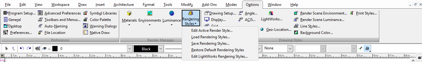
Render Styles
Advanced series of settings allowing you to create stylistic renders.
Default UI Menu: Options/Rendering Styles
Ribbon UI Menu:
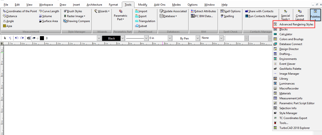
Using the Advanced Render Styles Palette
Default UI Menu: Tools/Palettes/Advanced Rendering Styles
Ribbon UI Menu:
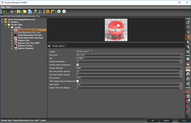
If no rendering style is selected the Render manager opens to the current category. Provides easy and fast access to render styles.
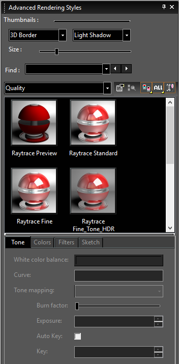
Categories
Specify the Render Style category.
Find Rendering Style
 To switch the render style display from thumbnails to list format, click View Thumbnails and select a different view.
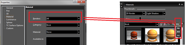
 TurboCAD has Lightworks rendering engines available. The Render Engine Filter allows you to specify which components will be displayed in the palette. ALL sets the palette to show all elements from all installed rendering engines. LW will show only LightWorks elements.
You can hide or show the palette fields and toolbars by clicking Show / Hide Options.
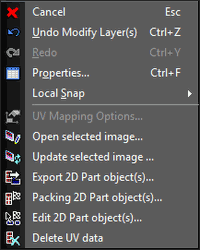
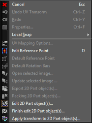
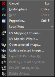
 Right-click on the Advanced Render Styles palette will open a local menu that provides a wide array of options.
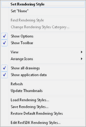 Set Render Style: Sets the currently selected Render style to the currently selected objects.
Set "None": Sets the render Style of the currently slected object to none.
Show Options: Toggle the display of the options on/off.
Show Toolbar: Toggle the display of the toolbar on/off.
View: Allows you to toggle on/off Thumbnails, List, Details
Arrange Icons: Allows you to spcify how the icons will be arranged: No arrange, By Name, By Name Inversely, By Category, By Category Inversely
Refresh: Refreshs the thumnails to reflect changes.
Update Thumnails: regenerates all of the thumbnails in the palette.
Load Rendering Styles... : Load render Styles from file.
Save Rendering Styles... : Saves the current render Styles
Remove Unassigned Rendering Styles: (This option only appears if the category is set to a Drawing Shader Manager) unused Render Styles will be removed from the palette.
Edit LightWorks Rendering styles...: Opens the Render manager. The Render manager is opened to the current material if one is selected. If no rendering style is selected the Render manager opens to the current category.
Set Render Style: Sets the currently selected Render style to the currently selected objects.
Set "None": Sets the render Style of the currently slected object to none.
Show Options: Toggle the display of the options on/off.
Show Toolbar: Toggle the display of the toolbar on/off.
View: Allows you to toggle on/off Thumbnails, List, Details
Arrange Icons: Allows you to spcify how the icons will be arranged: No arrange, By Name, By Name Inversely, By Category, By Category Inversely
Refresh: Refreshs the thumnails to reflect changes.
Update Thumnails: regenerates all of the thumbnails in the palette.
Load Rendering Styles... : Load render Styles from file.
Save Rendering Styles... : Saves the current render Styles
Remove Unassigned Rendering Styles: (This option only appears if the category is set to a Drawing Shader Manager) unused Render Styles will be removed from the palette.
Edit LightWorks Rendering styles...: Opens the Render manager. The Render manager is opened to the current material if one is selected. If no rendering style is selected the Render manager opens to the current category.
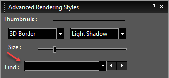
You can also search a render style in the palette. Type a word in "find" option to search, the first suitable item is highlighted. To browse through the styles, buttons next to the input field highlight and can be used to show the previous or next suitable item. Successful search options are added to the list and saved between sessions.
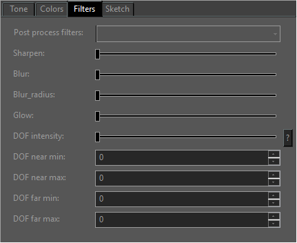
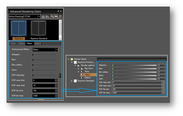
Set of post-effects has been added :
- Sharpen,Glow,
- Blur,
- Depth Of Field.
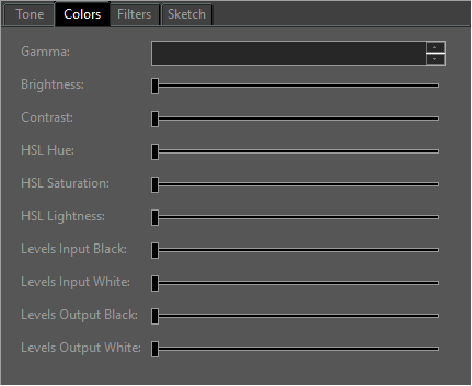
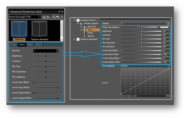
New color manipulation tools have been added : - Brightness / contrast controls,Hue Saturation Lightness controls, - Hue Saturation Lightness controls, - Input / output levels controls.
Interactive Color adjustments, Filters and Sketch rendering - Color adjustment - Filters - Sketch rendering
Color adjustment The ‘Colors’ section was added to the palette ‘Advanced Render Styles’. This section allows to edit the set of ‘Color adjustment’ parameters of the selected render style. These parameters comply with the same parameters in the Render Manager:
Filters The ‘Filters’ section was added to the palette ‘Advanced Render Styles’. This section allows to edit the ‘Filters’ parameters of the selected render style.
These parameters comply with the same parameters in the Render Manager:
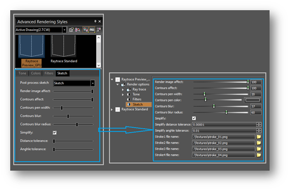
Sketch rendering:
The ‘Sketch’ section was added to the palette ‘Advanced Render Styles’. This section allows to edit the ‘Sketch’ parameters of the selected render style. These parameters comply with the same parameters in the Render Manager:
Limitations: Interactive post-processing is not available in the preview render in Render Manager. Note that if you change the tone mapping parameters of the rendering style in the Render Manager and press Ok, all windows with this style will render.
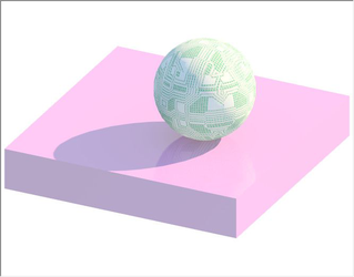
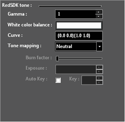
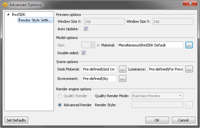
Interactive Tone Adjustments
Where a Render Style with Tone is used it is possible to dynamically adjust the tone settings after the render has been completed. The active Render Style must be selected in the palette to adjust the settings. To make sure that you have the active Render Style selected:
- Right Click in the Palette in the Thumbnail area.
- Click on Find Rendering Style.
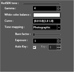
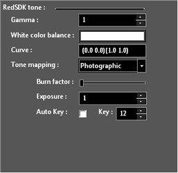
- The option for the RedSDK tone settings should now be available.

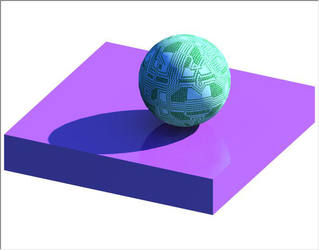
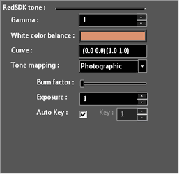
Adjusting the Gamma
Adjusting the White color balance
Adjusting the Curve
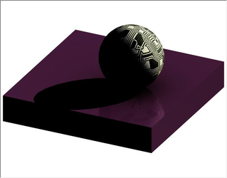
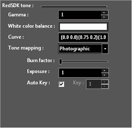
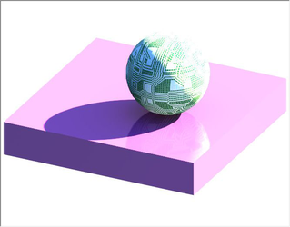
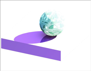
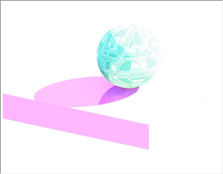
Adjusting the Tone Mapping
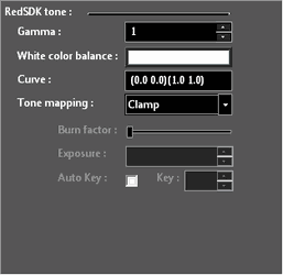
Adjusting the Burn factor
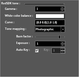
Adjusting the Exposure

Adjusting the Key
Loading and Saving Render Styles
Default UI Menu: Options/Rendering Styles/Load Rendering Styles, Options/Rendering Styles/Save Rendering Styles
Ribbon UI Menu:
If you want to save Render Style properties for future use, select Save Render Styles, or right-click in the Render Styles Palette and select Save Render Styles. Use the categories on the right side of the Save window to specify which render styles you want to save. Render style data will be written to a .dat file, located in the Render Styles folder. Any new render style you define will be automatically saved in the TurboCAD file as well.To load a render style .dat file, select *Load Render Styles from the Render Styles menu, or from the local menu of the palette.
Managing Render Styles in the Render Manager
 Or you can select a Render Styles on the Advanced Render Styles palette, right-click and select Edit Render Styles.
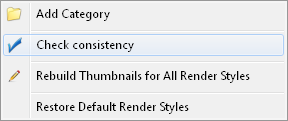
Right clicking on tree elements provides a variety of functions. Right clicking on Render Styles allows you to:
- Add Category
- Rebuild Thumbnails for all Render Styles
- Restore Default Render Styles
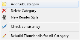
 Right clicking on a Category allows you to:
- Add SubCategory
- Delete Category
- New Render Style
- Rebuild Thumbnails for all Category
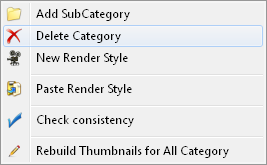
 If a render style has been copied you will also be allowed to:
- Paste Render Styles
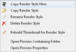
 Right clicking on a Render Style allows you to:
- Copy Render Style Here – adds a copy of the selected render style to the bottom of the current category.
- Delete Render Style
- Rename Render Styles
- Copy Render Styles – Copies the Render Style so it can be pasted elsewhere.
- Rebuild Thumbnail for Render Styles
 The toolbar on the Left side of the editor allows you to specify the elements of the preview.
 You can navigate within the preview window using the center mouse button.
Tone Mapping Control
The Tone Mapping control uses a curve based input control. The control consists of two parts: "Graph" part and "Text" part. The "Text" part presents the "reference" points, which are illustrated inthe "Graph" part by rectangles. The curve is constructed on the basis of the "reference" points using the Lagrange polynomials (with condition that x, y should be inside [0,1]). The curve must contain at least two points to be valid (0 0) and (1 1).
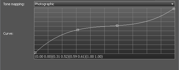 The curve can be edited as through the "Graph" part and through the "Text" part inthe following way:
- Adding the reference point. Can be done through the "Text" part by the adding the new pair (xi, yi) or by using the mouse, clicking on the "Graph" to set the point. It should be far enough from already created reference points (if it is too close to an existing point that point will be selected and ready for the dragging). If created by mouse the new point will be automatically selected and ready for the dragging.
- Changing the reference point. Can be done through the "Text" part by changing some pair (xi, yi) or by mouse by clicking and dragging.
- Removing the reference point. Can be done through the "Text" part by the removing the appropriate pair (xi, yi) or through the "Graph" part by using keyboard (pressing "Delete" button) when the mouse cursor is inside the rectangle of the appropriate point. The point must not be selected.
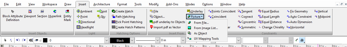
UV Mapping
Default UI Menu: Tools/UV Mapping Tools
Ribbon UI Menu:
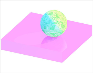
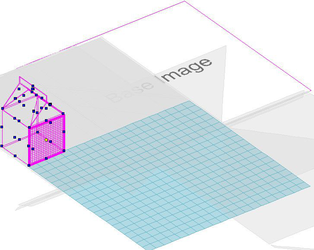
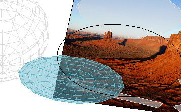
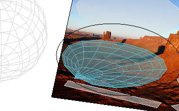
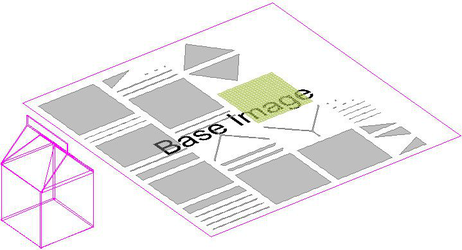
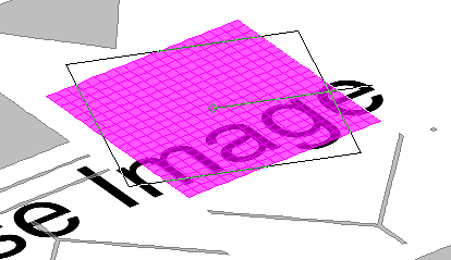
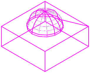
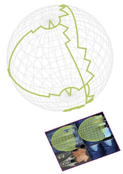
UV mapping is a method of projecting (wrapping) an image onto a 3D object. U and V indicate the axes of the image they are used in lieu of X Y Z to avoid confusion, since X Y, and Z are used to designate the axes of the 3D object. Color from the image is mapped to the polygons that compose the surface to the 3D object. In essence the process designates the where each area of the image is to appear on the 3D object. When a 3D object is rendered a mesh of that object is passed to the rendering engine. For surfaces, and Smeshes, the surface mesh itself is passed directly to the rendering engine. For solids, a mesh version of the solid is generated then passed to the rendering engine. Multiple images can be used where each image is mapped to discrete areas of the mesh. UV Mapping requires the following primary steps:
- Creating and inserting the image to be mapped
- Creating a UV Material
- Associating the image with the 3D object
- Unwrapping the mesh
- Refining the image
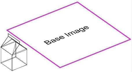
Associating the Image with the 3D Object
To associate an image with a 3D object:
- Select UV Mapping Tools
- Click on the Image
Note: You can only select the UV Mapping Tools if there is both an image and a 3D object in the drawing.
- Click on the 3D Object
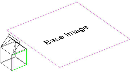
- The object and the facet you clicked on will become highlighted. At this point the image and the object are associated but not yet mapped.
Using Multiple Images
You can map multiple images to a 3D object. To do so follow these steps:
- Create a unique material for each image you wish to use.
- Insert each image you wish to use into the drawing.
- Use the Facet Editor to assign the correct material to each facet as needed.
- Select the Facet Editor.
- Select the facet(s) you wish to modify.
- Right click and select Propeties from the local menu.
- Navigate to the Materials page and assign the desired material. Then click OK.
- Map the correct image to each facet(s) as needed.
Creating and Inserting the Image
You can use any graphic tool to create your image, including TurboCAD. Image can be JPGs, PNGs, BMPs, or GIFs. The higher the resolution of the image the more refined the material will be on your model. You should consider an image of 1000x1000 as the bare minimum. You can insert a picture using either From File or From Image List.
Creating the UV Material
Use the Render Manager to create a new category; we suggest that you use "UV" as a name.
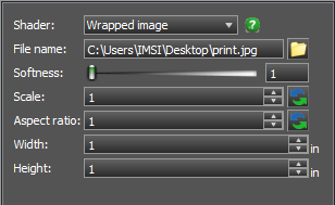
- Create a new material.
- Select the Pattern section of the material properties.
- Set the Shader to Wrapped Image.
- Specify the location of the file you will be using as your image.
- Set the Softness to 0. This will prevent fuzziness in your image.
- Select the Wrapping section of the material properties.
- Set the Shader to UV.
- Click OK to close the Render manager.
- Select the 3D object and assign the new material you created.
Proportional Editing
Proportional editing acts like a magnet to smoothly deform the UV part by modifying vertices within a given range. To use the tool:
- Activate UV mapping tools
- Select the Image
- Select the TC surface the selected TC surface should already have unwrapped segments.
- Enter the Edit 2D Parts mode
- Select a single 2D Part
- In the local menu choose Start Proportional Editing.
Specify the radius of editing area and lock the starting position of editing area.
The radius of editing area is defined in the UVmap coordinate system.
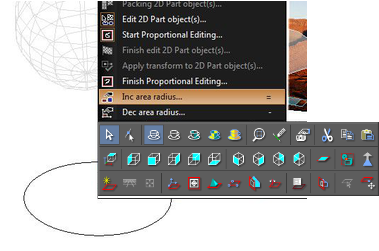 The radius of editing area can be changed in three ways:
A. Pressing the "+" and "-" buttons. B. Choosing the local menu items B. Manually specify the exact radius in the Edit bar
To lock the starting position of the editing area position the mouse and then click the left mouse button or press ENTER.
After fixing the editing area a user changes the points of 2D part by dragging the mouse.
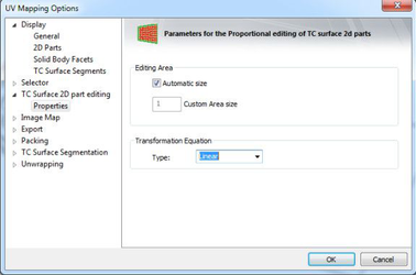
The manner in which points are moved is defined in the UV Properties in the Transformation Equation.
The radius of editing area can be changed in three ways:
A. Pressing the "+" and "-" buttons. B. Choosing the local menu items B. Manually specify the exact radius in the Edit bar
To lock the starting position of the editing area position the mouse and then click the left mouse button or press ENTER.
After fixing the editing area a user changes the points of 2D part by dragging the mouse.
The manner in which points are moved is defined in the UV Properties in the Transformation Equation.
 Constant transformation = No Falloff, all point move a once.
Linear transformation = Linear falloff
 Quadratic transformation = Smooth falloff
 Cubic transformation = Exponential falloff
 Sharp transformation = Steep falloff
 All the segments transformations are recorded in the Undo buffer, but Undo or Redo operations are possible only after leaving UVMapping.
Refining the Image
The primary process for improving or creating your finish image is by refining the image. There are two primary components:
- Export 2D Part Objects
- Move 2D parts as needed
Note: You can also review your image in your Windows default image editor or viewer by using Open the Selected Image.
 The process is to:
- Export 2D Part Objects
- Edit the result in your favorite image editor
- Update the Selected Image
- The repeat steps 2 and 3 (or 1, 2, 3 if necessary) until the image is as you need.
Original Image
 Refined Image
 Render Result
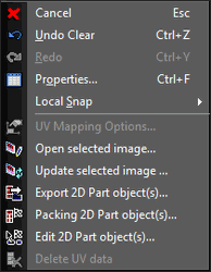
Export 2D Part Objects
You can access the Export 2D Part objects via the UV Mapping tools local menu. At least one facet must be selected in order for this option to appear. When exporting only the facets that are selected will be used/embedded in the export.
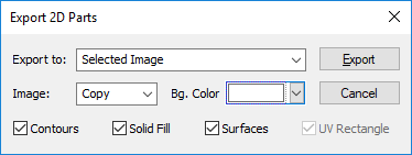
Export to
- Selected Image – Export result to the selected images file.
- New Drawing – Open a new CAD drawing and embed result
- Current Drawing – Embed the result into the current CAD drawing.
Image –
- Add – Destination = Destination + Source (If the amount is greater than 255, the result is 255
- And – Destination = Destination & Source (Bitwise AND two images)
- Xor – Destination = Destination xor Source (Bitwise XOR two images)
- Or – Destination = Destination or Source (Bitwise OR two images)
- Copy – Destination = Source
- Sub – Destination = Destination – Source
- Blend – Destination = Source + degradation
- Screen – Destination = Destination + Source + degradation (The result image will have a lighter tonality)
- Avg – Destination = (Destination+ Source)/2
Bg. Color – Set the background color for the resulting image. Contours – Export the contours to the result. Solid Fill – Export the solid fills to the result. Surfaces – export the surfaces to the result. UV Rectangle – (not available for Selected Image)
Update the Selected Image
You can Update the Selected Image used for any UV Mapping.
- Selected the UV Mapping Tools.
- Select the Image.
- Right click and select Update the Selected Image from the local menu.
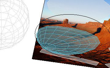
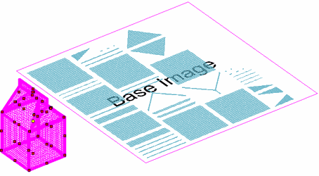
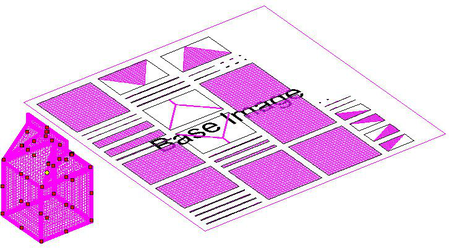
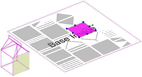
Unwrapping the Mesh
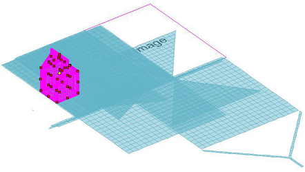
Once you have associated an image to a 3D object you will need to unwrap the facets of the 3D object into 2D parts that can be arranged on the image. This will allow you to 'map' which part of the image is to appear on each facet.
The following applies equally to unwrapping ACIS Solids and Surfaces.
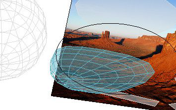
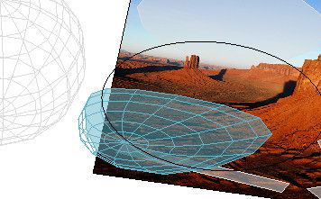
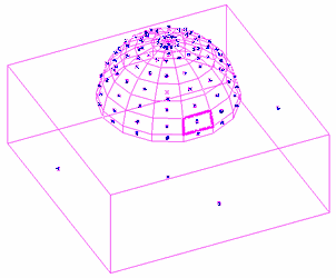
You can individually select facets on the 3D object, or select all of the facets.
To selcect an individual facet, click on the blue node of that facet. To select multiple individual facets, hold down the shift key and then click on each facet's blue node.
To select all of the facets drag a selection rectagle around the entire 3D object.
 At this point you will want to begin arraging the 2D parts. There are two complementory methods to do this: Packing and Editing.
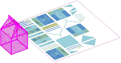
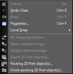
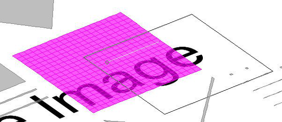
Packing 2D Parts
Packing is a algorythmic method of arrange a group object within a defined space. For UV Mapping, packing arranges all of the 2D parts within the area defined by the image. To pack the 2D parts:
-
Select the desired facets.
-
Right click and select Packing 2D Part object(s) ...
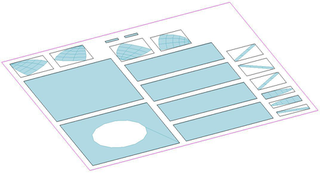
- The 2D parts will automatically be laid out on the associated image.
-
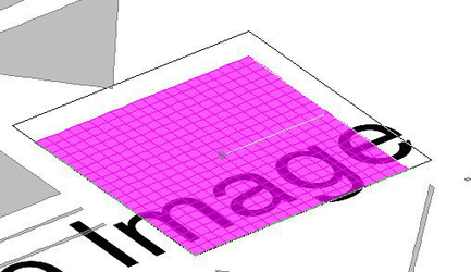
You can un-pack the parts by clicking Packing 2D Part object(s) ... again.
-
If you have un-packed you can re-pack by agin clicking Packing 2D Part object(s) ... The second time you pack the arrangement will be adjusted. To get back to the original packing arrangement. un-pack and repack once more.
-
When you are done packing right click and select Finish packing 2D Part object(s)...
To de-select facet click away from the 3D object and image.
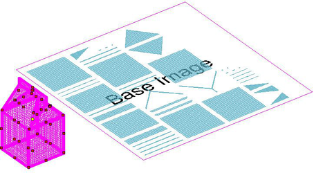
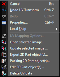
Editing 2D Parts
You can move, rotate, and scale parts to arrange them better for your purposes.
-
Select a facet or facets
-
Right click and select Edit 2D part object(s)...
-
The selected part(s) will be highlighted to indicate that it can be edited.
-
Click on the part(s) to begin editing.
- You can then edt the part by standard methods:
Move
Scale
Rotate
- You can finish any one alteration by right clicking and selecting Apply transform to 2D Part object(s).
- To complete editing right click and slect Finish edit 2D Part object(s).
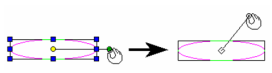
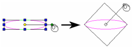
Inversed Normals
Occasionally the part and the image will map with an inversed normal. This means the section of the image appears backward on the facet. To remedy this You need to reverse the layout of the 2D part. Select the part then use the middle blue node on the edge and drag in past the opposite edge. You can now reposition the newly edges, as long as you do not recross their positions. The edge you select depends upon how the reversal appears, in other words is it reversed along the X or Y axis. You cannot simply scale -1 along the X or Y axis via the Edit bar. This will only flip the part but the reversed association will remain. Do not flip the 2D part via rotation. This will only flip the part but the reversed association will remain.
Unwrapping Surfaces
In addition to the basic UV Mapping funtions there are some additional functions for mapping surfaces.
Since it is generally undesirable to export every single facet of a surface as an individual 2D part the Surface functions are designed to gather groups of facets to create Segments of the 3D object. The resulting segment can then be converted into editable 2D parts.
The functions and ther purpose are as follows:
Quick Selection: Selects a contiguous series of facets based on the setting in the UV Mapping Options.
 Create Segment by Selection: Creates a segment based on the currently selected facets.
 Auto Segmentation: Automatically composites a set of segments for all facets of the selected 3D object.
 Explode Segements: Explode the currently selected facets back into facets.
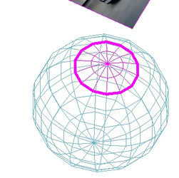
 Unwrap Segments: Unwrap the selected segments into 2D Parts.
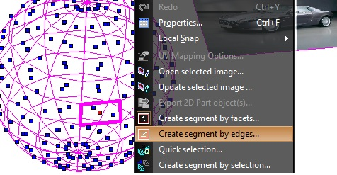
 Select segment by edges:
To activate the tool:
- Activate UV mapping tools
- Select the Image
- Select a TC surface
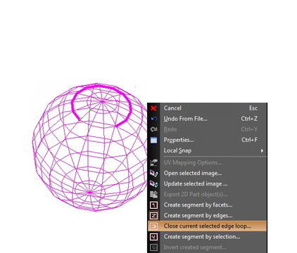
- Select "Create segment by edges…"
 After that, select a closed edge loop. For this there are two possibilities:
- Manual - Select the edge loop manually by clicking one edge after the other. All selected edges should be connected. This means that you can only select those edges which have common vertices with those already selected. Another limitation for each vertex there can only be two edges from the selected edge loop this prevents self-intersections.
- Mixed manual and automatic. If you have already have selected a few edges, but not closed, you can try to close edge loop automatically by selecting Close current selected edge loop… The program will try to find the shortest path between the ends of the currently selected edges and connect them.
 After creating of the closed loop, you can create a segment by seleting Create segment by selection…
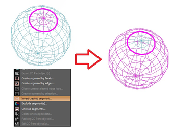
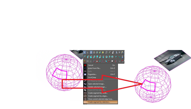 For the each closed edge loop it is possible to create two segments; One from internal facets, the other from the external facets. The algorithm will automatically choose one of these domains. If the algorithm choose the opposite domain from the one you wanted select Invert created segment… which will invert the selection to the alternate facets.
 It is important to note, that Invert created segment… will only function immediately after using Create segment by selection…
UV Mapping Options
You can access the UV Mapping Options by:
- Selecting the UV Mapping Tools
- Right click and select UV Mapping Options.
Note: You can only select the UV Mapping Tools if there is both an image and a 3D object in the drawing.
Additional Manipulation Options
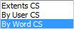
Coordinate System Extents by – Sets the coordinate system (workplane) used by the selector shell. Because these settings work in tandem with other settings, their performance can become complex
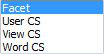
Edit Bar CS – Sets which coordinate system will be used in the Edit Bar.
Display-2D Part
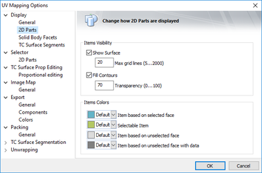
- Show Surface – Surfaces with their gridlines will be shown
- Max grid lines (5…2000) - defines the parameters of ACIS Refinement that are used to derive 2D polygonal meshes for surfaces. The greater the parameter value, the more precise the ACIS refinement will be, which also means a greater impact on time and memory.
- Fill Contours – Show a fill for 2D parts.
- Transparency (0…100) – set the transparency level for fills.
- Item based on selected face – Set the color 2D parts associated to selected faces on the 3D object.
- Selectable Item – Set the color for 2D parts which can be selected but are not.
- Item based on unselected face – Set the color 2D parts associated to un-selected faces on the 3D object.
- Item based on unselected face with data – Set the color 2D parts associated to un-selected faces on the 3D object which have UV Mapping already associated.
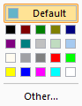
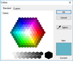
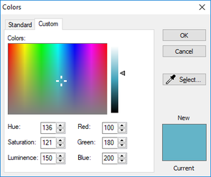
You can use the standard color pickers to assign the colors.
Display-General
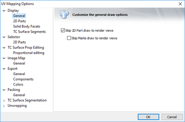 The purpose of the General page is to control drawing of various objects in rendered views.
- Skip 2D Part draw to render views – stops rendering of 2D Part objects.
- Skip Marks draw to render views – stops rendering of marks.
Export-Components
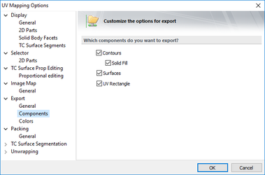 Contours – the contours will be exported.
- Solid Fill – the solid fills will be exported.
Surfaces – the surfaces will be exported. UV Rectangle – the UV Rectangle will be exported.
Export-Colors
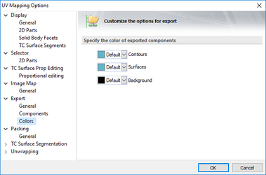 Color for exported components
- Contours – set the color for exported contours.
- Surfaces – set the dolor of exported surfaces.
- Background – set the color of the exported background.
Export-General
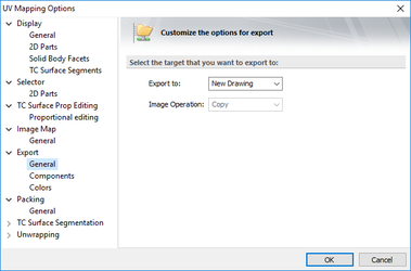 Export to – How will the image be exported:
- New Drawing – In a new CAD Drawing
- Current Drawing – Into the Current CAD Drawing
- Selected Image – Out to the Selected Image's file.
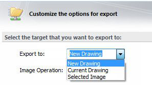
Image Operation – This sets the method by which the Destination (Image File) is combined with the Source (exported 2D Objects). The color is combined for each RGB color channel per pixel.
- Add – Destination = Destination + Source (If the amount is greater than 255, the result is 255
- And – Destination = Destination & Source (Bitwise AND two images)
- Xor – Destination = Destination xor Source (Bitwise XOR two images)
- Or – Destination = Destination or Source (Bitwise OR two images)
- Copy – Destination = Source
- Sub – Destination = Destination – Source
- Blend – Destination = Source + degradation
- Screen – Destination = Destination + Source + degradation (The result image will have a lighter tonality)
- Avg – Destination = (Destination+ Source)/2
Image Map-General
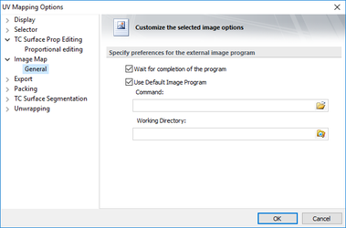
- Wait for completion of the program – the program will get control only after the other program finishes its work.
- Use Default Image Program – set that image editing will use a default defined application.
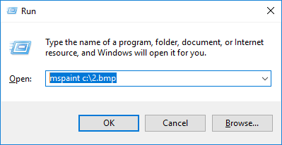
- Command – any string command that can be entered, for example, Run: dialog.
- Working Directory – the default working directory for the image files.
Packing-General
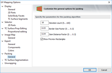 Specify the parameters for the packing algorithm
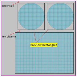
Iteration count (5…100) – the number of iterations used by the packing algorithm. The greater the number, the better (packing is tighter), but the more time is spent on calculations. Border Size Factor (0…0.3) – the factor that affects the field size of parts. The smaller it is, the smaller the field. Item Distance Factor (0…0.3) – the factor that affects the distance between packed objects. The smaller it is, the smaller the distance. Show Preview Rectangles – if this option is on, then an outline rectangle is drawn around the packed objects. Show Preview Rectangles – Show the boundary rectangles around parts.
Specify the parameters for the packing algorithm
Iteration count (5…100) – the number of iterations used by the packing algorithm. The greater the number, the better (packing is tighter), but the more time is spent on calculations. Border Size Factor (0…0.3) – the factor that affects the field size of parts. The smaller it is, the smaller the field. Item Distance Factor (0…0.3) – the factor that affects the distance between packed objects. The smaller it is, the smaller the distance. Show Preview Rectangles – if this option is on, then an outline rectangle is drawn around the packed objects. Show Preview Rectangles – Show the boundary rectangles around parts.
Selector-2D Parts
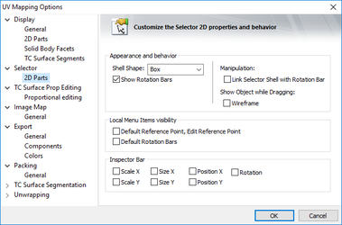 Shell Shape: Select None to make the selector shell (bounding rectangle) invisible.
Show Rotation Bars: If unchecked, the rotation bar is not shown and is not accessible.
Link Selector Shell with Rotation Bar: If checked, when you press Ctrl and move the rotation handle, the selector shape will change accordingly.
Link Selector Shell not checked
Shell Shape: Select None to make the selector shell (bounding rectangle) invisible.
Show Rotation Bars: If unchecked, the rotation bar is not shown and is not accessible.
Link Selector Shell with Rotation Bar: If checked, when you press Ctrl and move the rotation handle, the selector shape will change accordingly.
Link Selector Shell not checked
 Link Selector Shell checked
 Show Object while Dragging: Displays the selected objects dynamically as they are transformed. If not checked, only the selection shell is visible.
- Wireframe – In wireframe mode.
Edit Bar Visibility: Controls the 2D transformation fields that appear on the Edit bars. Local Menu Items visibility:
- Default Reference Point, Edit Reference Point – Show the options in the Local menu.
- Default Rotation Bars – Show the Rotation bars.
TC Surface Segmentation-General
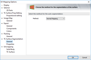 Select the method for the auto segmentation:
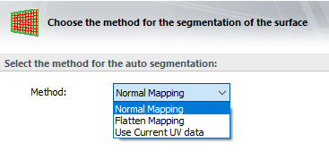 Method – sets the method of mapping.
- Normal Mapping – method of mapping applies planar maps based on directional procedures. It is the simplest method, but can result in greater texture distortion.
- Flatten Mapping – method of mapping applies planar maps to contiguous polygons that are within a specified angle threshold. It prevents overlap of mapping clusters, but can still cause texture distortion. The Flatten Mapping dialog lets you control how clusters are defined and mapped.
TC Surface Segmentation-Properties
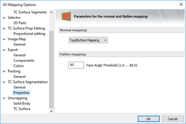 Normal Mapping
- Top/Bottom mapping – Mapping originates from top and bottom.
- Back/Front Mapping – Mapping originates from front and back.
- Left Right Mapping – Mapping originates from left and right (relative to the a World CS)
- Box Mapping – Mapping originates from cubically.
Flatten Mapping Face Angle Threshhold (1.0…89.0) – The maximum angle that can exist between faces in a 2D part. As Flatten Mapping collects faces to be mapped, this parameter is used to determine which polygons it are combined. The higher the number is the larger the parts that result will be.
Unwrapping-Solid Body
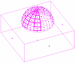
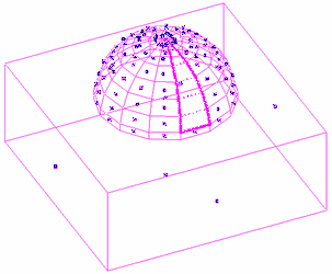
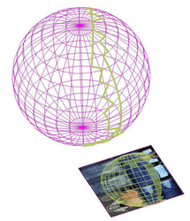
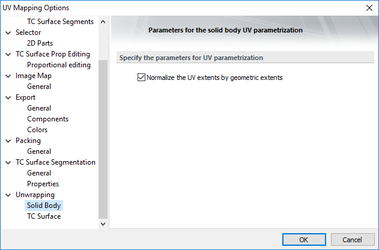 Normalize the UV extents by geometric extents – 2D parts are a visualization of ACIS facets. Different types of facets have different scale in ACIS. For example, periodic facets (sphere, cone) are limited in size from -Pi (3.14) to +Pi (3.14). If this option is off, 2D parts have exactly the dimensions that are given to them by ACIS. If it is on, then the 2D part is changed in size in accordance with their geometric dimensions.
Off
Normalize the UV extents by geometric extents – 2D parts are a visualization of ACIS facets. Different types of facets have different scale in ACIS. For example, periodic facets (sphere, cone) are limited in size from -Pi (3.14) to +Pi (3.14). If this option is off, 2D parts have exactly the dimensions that are given to them by ACIS. If it is on, then the 2D part is changed in size in accordance with their geometric dimensions.
Off 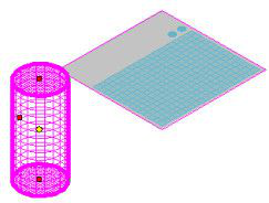 On
On 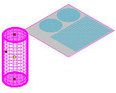
Unwrapping-TC Surface
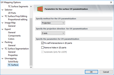
Specify method for the UV parametrization
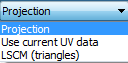
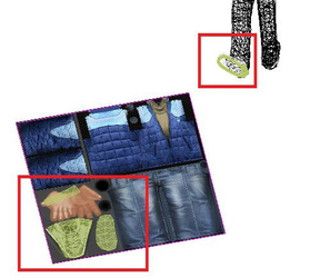
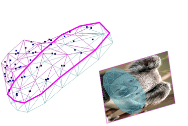
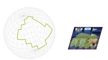
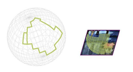
Projection - In this case for the UV parametrization of each facet the coordinates are projected on a certain plane Use current UV data - In this case it is used the texture coordinates which are already set. This method can be useful for the models which come from other programs, where the texture coordinates were set (on the picture below it is possible to see the example for the model from SketchUP).
LSCM (Triangles) - Least Squares Conformal Maps is a more complex algorithm, which allows us to receive better unwrapping results. There is one important restriction for the current implementation of this algorithm, namely all facets must be triangles.
For example, this segment has facets which are practically orthogonal to each other
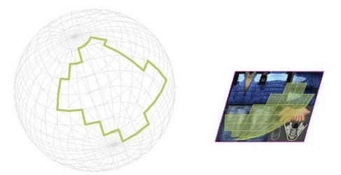
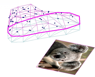 The result is as follows with the Projection method.
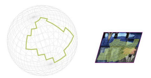
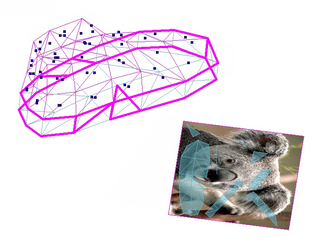 However, with LSCM the following results will occur.
.
However, with LSCM the following results will occur.
. 
Specify the projection direction for UV parametrization
Note: This option is valid only for the Projection method.
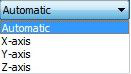 Automatic - In this case the direction of the projection is chosen automatically by the program.
 X-axis - In this case as a projection direction the X – axis of the current workplane is used.
 Y-axis - In this case as a projection direction the Y – axis of the current workplane is used.
 Z-axis - In this case as a projection direction the Z – axis of the current workplane is used.
Specify the parameters direction for UV parametrization
Fix self-intersections in 2D parts - This option affects the presence of self-intersecting facets in 2D parts. This can lead to artifacts in rendering. When this option is enabled, during unwrapping presence of self-intersections is checked, and an attempt of resegmentation is made with the purpose to remove self-intersections. This procedure may take a few iterations and considerable time but it is recommended for the complex bodies.
When Unchecked (option is disabled)
When Checked (option is enabled)
 Remove holes in 2D parts - When this option is enabled, an attempt to merge the large and small 2D parts will be made. It will require to reduce the number of small 2D parts.
Note: This option is valid only for the Projection method.
UV Material Wizard
The Material wizard automates the process of creating a UV compatible material. To use the Material wizard:
- Go to Tools.
2. Select UV Mapping Tools. (This will only be available if there is atleast one 3D object in the model)
Optionally: Click on an image to select it. And/Or Click on a 3D object to select it.
3. Right click and select UV Material Wizard .
4. Set the parameters in the Wizard dialog, and then press OK.
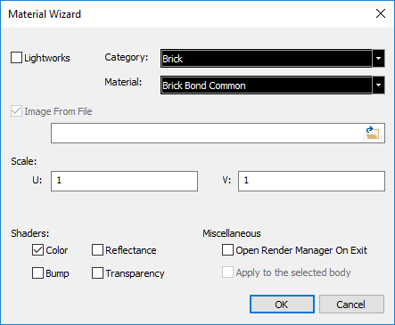
PARAMETERS LightWorks - If selected a Lightworks material is created. Category - Set the category in which the material will reside. Material - Select or type in the name for the material. Image From File - If you pre-selected an image this will be unchecked, and the file and path field will be filled. File and Path field - If unfilled use the adjacent File Open button start the File Open dialog, and then locate and select an image. File Open button - Opens the File Open dialog. Scale: U - Set the U scale for the material. V - Set the V scale for the material. Shaders: Color - Set whether the image will be used to specify the color or pattern of the material. Reflectance - Set whether the image will be used to specify the color intensity or Reflectance pattern of the material. Transparency - Set whether the image will be used to specify the color intensity or Transparency pattern of the material. Bump - Set whether the image will be used to specify the color intensity or Bump pattern of the material. Open render Manager on Exit - I checked the Render Manager will open when you press OK. Apply to the Selected body - If checked and if you pre-selected a 3D object the new material will be assigned to that object.