Importing and Exporting Files
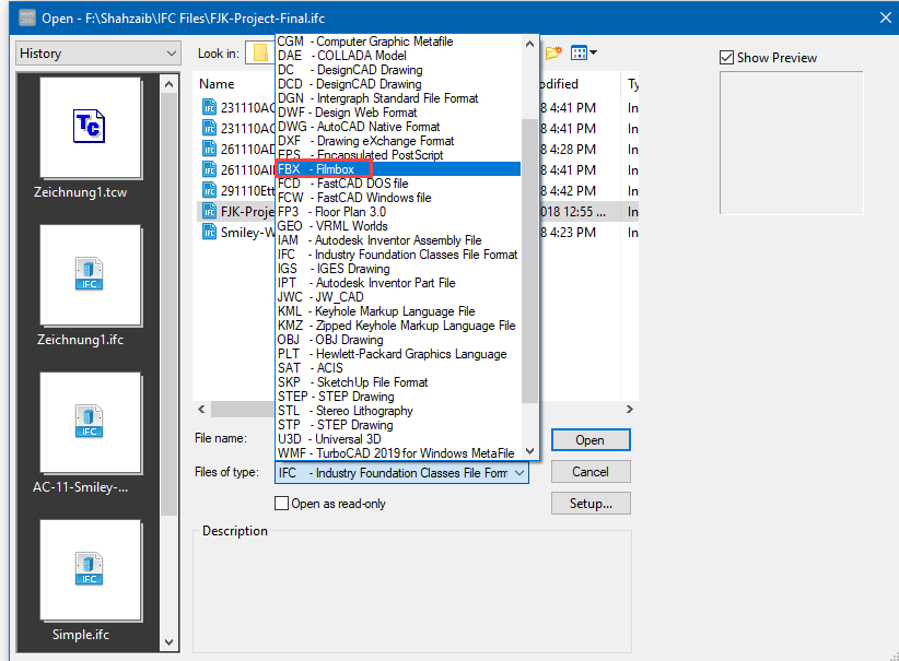
You can import and export data from other TurboCAD formats, as well as formats of other CAD systems. To import from another file type:
- Select File / Open or Ctrl+O.
- Under Files of type, select the format you want to import.
- If you want to specify conversion parameters, click Setup.
- Browse to the file, and double-click it or click Open.
To export to another file type:
- Select File / Save As.
- Under Save as type, select the format to which you want to export.
- If you want to specify conversion parameters, click Setup.
- Browse to the folder and assign a file name.
To import or export only certain components of a file, use File / Extract From or Extract To. For example, you can choose to import a drawing's layers and blocks, or export only print styles. To insert the contents of another file as a block, create an external reference (xref).
For a list of all supported CAD and Graphics file formats,
File Converter
(Plugin)
Opens the TurboCAD File Converter window, in which you can select a source and destination folder for batch conversion. Use the Files of type field to select the conversion format. Click Run to convert all files in the selected folder and place the converted files in the target folder.
Other CAD and Graphics Formats
The following formats can be read by TurboCAD, either for import, export, or both. Some formats have a Setup in which you can set certain parameters for conversion. If you do not specify conversion parameters, the defaults will be used. (If no Setup is indicated, the conversion requires no additional input.)
| Import and Export ✓ | Import Only ✓* | Export Only ✓** | |||
|---|---|---|---|---|---|
| File Format | Description of file format | Platinum | Professional | Deluxe | Designer |
| DWG | AutoCAD® native format | ✓ | ✓ | ✓ | ✓ |
| DWF | Autodesk® Drawing Web Format | ✓ | ✓ | ✓ | ✓ |
| DXF | Drawing Exchange format | ✓ | ✓ | ✓ | ✓ |
| 3DM | Rhino format | ✓ | |||
| 3DS | Autodesk® 3D Studio format | ✓ | ✓ | ✓ | |
| 3DV | VRML Worlds | ✓* | ✓* | ✓* | ✓* |
| ASAT | ACIS® | ✓ | |||
| ASC, PCD, PCG | Point Cloud Data | ✓* | |||
| BMP | Windows® Bitmap format | ✓** | ✓** | ✓** | ✓** |
| CGM | Computer Graphics Metafile | ✓ | ✓ | ✓ | ✓ |
| DAE | COLLADA Model | ✓ | ✓** | ✓** | |
| DC, DCD | DesignCAD® format | ✓* | ✓* | ✓* | ✓* |
| DGN | Intergraph Microstation | ✓ | ✓ | ✓ | |
| EPS | Adobe® PostScript | ✓ | ✓ | ✓ | |
| FCD, FCW | Fast CAD format | ✓* | ✓* | ✓* | |
| FBX | 3D asset exchange format | ✓ | ✓ | ✓ | |
| GEO | VRML Worlds | ✓* | ✓* | ||
| GIF | Graphics Interchange format (w/ Alpha Channel Support) | ✓** | ✓** | ✓** | ✓** |
| IFC | Industry Foundation Classes | ✓ | ✓* | ||
| IGS | IGES Drawing | ✓ | |||
| JPG | JPEG | ✓** | ✓** | ✓** | ✓** |
| JPG | SDK sample filter JPEG | ✓** | |||
| KML, KMZ | Google Map Format | ✓* | ✓* | ✓* | |
| OBJ | OBJ Drawing | ✓ | ✓ | ||
| Adobe® Portable Document Format | ✓** | ✓** | ✓** | ✓** | |
| Adobe® 3D Portable Document Format | ✓** | ||||
| Adobe PRC Portable Document Format | ✓** | ||||
| PLT | Plotter file format language | ✓ | ✓ | ✓ | ✓ |
| PNG | Portable Network Graphic (w/ Alpha Channel Support) | ✓** | ✓** | ✓** | ✓** |
| PRC | Product Representation Compact (3D PDF) | ✓** | |||
| Raster | (Reference 2D multiple formats) | ✓ | ✓ | ✓ | ✓ |
| SAT | ACIS® | ✓ | |||
| SAB | ACIS® | ✓ | |||
| SHX | Shapefile format | ✓** | ✓** | ||
| SKP | Trimble SketchUp® format | ✓ | ✓ | ✓ | |
| STEP | STEP Drawing | ✓ | |||
| STL | Stereolithography format | ✓ | ✓ | ✓ | |
| STP | STEP Drawing | ✓ | |||
| SVG | Scaleable Vector Graphics | ✓** | ✓** | ✓** | |
| TAP | TurboApps® packaged file format | ✓* | ✓* | ||
| TCT | TurboCAD® drawing template | ✓ | ✓ | ✓ | ✓ |
| TCW | TurboCAD® native format | ✓ | ✓ | ✓ | ✓ |
| U3D | Universal 3D | ✓ | ✓** | ||
| WMF | Windows® Metafile | ✓ | ✓ | ✓ | ✓ |
| WRL | VRML Worlds | ✓ | ✓ | ✓ | ✓ |
| WRZ | VRML Worlds | ✓ | ✓ | ✓ | ✓ |
| XYZ | Terrain Data | ✓* | ✓* | ||
| 3MF | 3D Manufacturing Format | ✓** | ✓** | ✓** |
Note: IGS is a file format for a public domain called IGES which is actually a neutral file format intended as an international standard for the exchange of data between different CAD/CAM systems. IGES is an ANSI standard maintained by the IGES/PDES Organization (IPO), under the direction of the National Institute of Standards and Technology (NIST). The National Computer Graphics Association (NCGA) acts as the administrator of the standard.
SKP File Import Setup
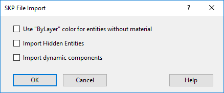 Use "ByLayer" color for entities without material: Assign the SketchUp layer color to any entity that does not have an assigned material.
Import Hidden Entities: Imports entities which are hidden in the SKP. If this option is off hidden entities will nor be imported.
Import dynamic components: Dynamic block are imported as PPM objects.
SKP materials are imported and supported for both RedSDK and Lightworks.
Use "ByLayer" color for entities without material: Assign the SketchUp layer color to any entity that does not have an assigned material.
Import Hidden Entities: Imports entities which are hidden in the SKP. If this option is off hidden entities will nor be imported.
Import dynamic components: Dynamic block are imported as PPM objects.
SKP materials are imported and supported for both RedSDK and Lightworks.
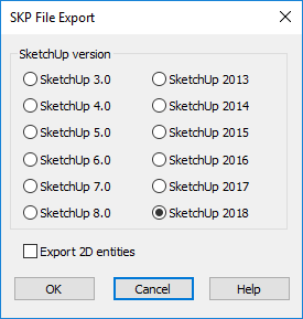
SKP File Export Setup
SketchUp Version: Specify the version of SketchUp SKP to be used in the file format: 5, 6, 7, 8, to 2017.
Note: The 2017 format is only supported on 64-bit versions of TurboCAD.
3DS File Import Setup
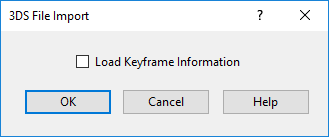 Load Keyframe Information: Accepts or ignores the keyframe 3DS file data.
Materials can also be imported in 3DS format.
- Additions made to import RedSDK materials.
- Issue with lost materials is now fixed.
- Issue with lost texture coordinates is now fixed.
Without Texture:
With Texture:
3DS File Export Setup
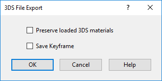 Preserve loaded 3DS materials: Saves unique materials from a 3DS file. If not checked, saves TurboCAD materials.
Save Keyframe: Saves the hierarchical structure of entities in a file. Do not check this option for 3DS files that you want to use as 3DS symbols in TurboCAD.
Preserve loaded 3DS materials: Saves unique materials from a 3DS file. If not checked, saves TurboCAD materials.
Save Keyframe: Saves the hierarchical structure of entities in a file. Do not check this option for 3DS files that you want to use as 3DS symbols in TurboCAD.
BMP Export Setup
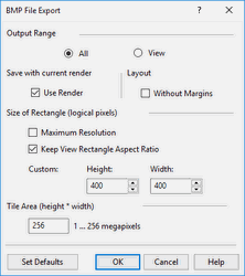 Output Range: Creates an export file either out of the entire drawing (All) or only the part that is currently in view (View).
Use Render: Available only when Render or Hidden Line mode is active. If checked, the exported image will show the render displayed on the screen.
Size of Rectangle: Sets up the resolution for the exported graphics. By default, these values are 400 x 400 but you can customize the height and width
Maximum resolution: The drawing will be defined by a rectangular matrix of 2000 x 2000 logical pixels. If there is at least one image object, this is set to 1000 x 1000.
Keep View Rectangle Aspect Ratio: Keeps the same ratio of length to width.
Output Range: Creates an export file either out of the entire drawing (All) or only the part that is currently in view (View).
Use Render: Available only when Render or Hidden Line mode is active. If checked, the exported image will show the render displayed on the screen.
Size of Rectangle: Sets up the resolution for the exported graphics. By default, these values are 400 x 400 but you can customize the height and width
Maximum resolution: The drawing will be defined by a rectangular matrix of 2000 x 2000 logical pixels. If there is at least one image object, this is set to 1000 x 1000.
Keep View Rectangle Aspect Ratio: Keeps the same ratio of length to width.
Note: You can determine an object's type by using the Selection Info Palette.
CGM Import Setup
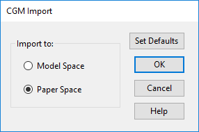 Choose to open the file either inModel Space or Paper Space.
DGN Import Setup
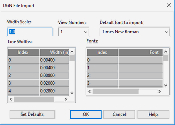 View Number: By default, the view number is 1.
Line Widths: You customize a set of drawing line widths identified by the indexes (0, 1, 2, etc.). To do this, use the two-column Line Width control , where the Index column provides a reference to particular line width, and the Width column is a data entry field. You can scale the line width values, using the Width Scale data entry field.
Fonts: As with the drawing line widths, the import file's fonts are indexed. For every index in the Index column, you can select a font from the corresponding drop-down list in the Font column. In addition to the options of the Fonts control, there is the Default Font entry field whose drop-down list lets you select a common font for the ones you haven't changed.
Set Defaults: Instead of customizing the imported file options, you can apply the default settings for the DGN file import. To do this, click Set Defaults.
View Number: By default, the view number is 1.
Line Widths: You customize a set of drawing line widths identified by the indexes (0, 1, 2, etc.). To do this, use the two-column Line Width control , where the Index column provides a reference to particular line width, and the Width column is a data entry field. You can scale the line width values, using the Width Scale data entry field.
Fonts: As with the drawing line widths, the import file's fonts are indexed. For every index in the Index column, you can select a font from the corresponding drop-down list in the Font column. In addition to the options of the Fonts control, there is the Default Font entry field whose drop-down list lets you select a common font for the ones you haven't changed.
Set Defaults: Instead of customizing the imported file options, you can apply the default settings for the DGN file import. To do this, click Set Defaults.
DGN Export Setup
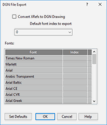 Version: Choose between Versions 7 and 8.
Default font index to export: The DGN format requires the export file's fonts to be indexed. For every listed font, you can select an index. In addition to the options of the Fonts control, there is the Default Index entry field whose drop-down list lets you select a common index for the fonts you have not changed.
Version: Choose between Versions 7 and 8.
Default font index to export: The DGN format requires the export file's fonts to be indexed. For every listed font, you can select an index. In addition to the options of the Fonts control, there is the Default Index entry field whose drop-down list lets you select a common index for the fonts you have not changed.
DWF Export Setup
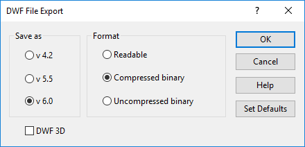 Output Format: If Readable is selected, you can later open the exported file to view and/or edit via a text editor.
Skip Invisible Layers: Invisible layers will not be included in the export file.
DWF 3D: DWF files of 6.01 format will be created. Files will contain all elements from Model Space, including 3D.
Output Format: If Readable is selected, you can later open the exported file to view and/or edit via a text editor.
Skip Invisible Layers: Invisible layers will not be included in the export file.
DWF 3D: DWF files of 6.01 format will be created. Files will contain all elements from Model Space, including 3D.
Note: TurboCAD does not support importing from this format. DWF files created with this option can be viewed either in Autodesk DWF Viewer (v6.01 and up), or in other applications that support this format.
DXF (DWG) 2019 Import Setup
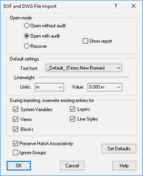 Open mode:
Open without audit: Opens the file without checking it. If the file has errors, it will not be opened.
Open with audit: Opens the file and corrects errors when possible. The report is displayed only if errors are found. The file is checked is after it is loaded into memory, though if the file is very corrupt it may not be able to be loaded into memory.
Recover: Opens the file and corrects errors. The report is automatically displayed, regardless of errors. The file is checked before loading it into memory.
File Units: Replaces the units of an imported file with the selected units.
Default text font: Sets a default import font.
Lineweight Unit and Value: Defines how objects using the AutoCAD default line weight are treated on import.
Overwrite existing entries for: AutoCAD stores the settings (or values) for its operating environment and some of its commands in system variables. Checking this box overwrites these settings. In TurboCAD, these settings include World units, the numerical display format, the angular system, etc.
You can overwrite system variables for objects under the following conditions: the DXF/DWG drawing is inserted into an open file, and both files (the imported file and the receiving file), have system variables (views, blocks, layers and/or line styles) of the same names.
DWG and DXF file formats do not support unit types, only a designation as Imperial or Metric. All Imperial units are converted to inches in DWG, all Metric units to mm.
Open mode:
Open without audit: Opens the file without checking it. If the file has errors, it will not be opened.
Open with audit: Opens the file and corrects errors when possible. The report is displayed only if errors are found. The file is checked is after it is loaded into memory, though if the file is very corrupt it may not be able to be loaded into memory.
Recover: Opens the file and corrects errors. The report is automatically displayed, regardless of errors. The file is checked before loading it into memory.
File Units: Replaces the units of an imported file with the selected units.
Default text font: Sets a default import font.
Lineweight Unit and Value: Defines how objects using the AutoCAD default line weight are treated on import.
Overwrite existing entries for: AutoCAD stores the settings (or values) for its operating environment and some of its commands in system variables. Checking this box overwrites these settings. In TurboCAD, these settings include World units, the numerical display format, the angular system, etc.
You can overwrite system variables for objects under the following conditions: the DXF/DWG drawing is inserted into an open file, and both files (the imported file and the receiving file), have system variables (views, blocks, layers and/or line styles) of the same names.
DWG and DXF file formats do not support unit types, only a designation as Imperial or Metric. All Imperial units are converted to inches in DWG, all Metric units to mm.
DXF (DWG) 2019 Export Setup
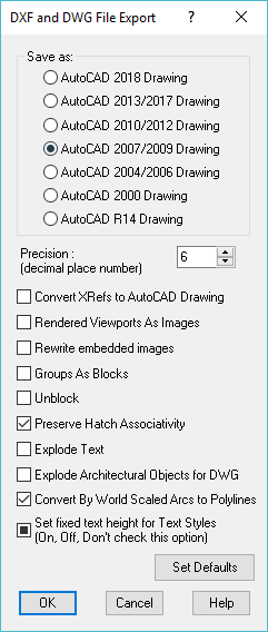 Save As: Select the AutoCAD version. TurboCAD now support DWF export till 2019.
Precision: The number of decimal places for numerical values of the exported file.
Convert Xrefs to AutoCAD Drawing: Converts attached Xrefs into DWG files.
Rendered Viewports as Images: All viewports that have renderings will be converted to images, to preserve the appearance of the renderings.
Rewrite embedded images: Relevant for files that contain image objects. Choose whether to replace images.
Groups as Blocks: Displays objects included in groups as blocks when imported into AutoCAD.
Unblock: Explodes blocks into its constituent objects.
Preserve Hatch Associativity: Retains hatch association in the resulting DWG file.
Explode Text: Explodes any text into its constituent parts.
Explode Architectural Objects for DWG: Explodes any TurboCAD Architectural objects into data comprehensible to AutoCAD.
Convert By World Scaled Arcs into Polylines: All arc using the By World setting for line scaling will be converted into arc segments of polylines with a supported AutoCAD scaling method.
Set Fixed Height for Text Styles: (On, Off, Don't check this option): Locks Height for Text Styles.
DWG and DXF file formats do not support unit types, only a designation as Imperial or Metric. All Imperial units are converted to inches in DWG, all Metric units to mm.
Save As: Select the AutoCAD version. TurboCAD now support DWF export till 2019.
Precision: The number of decimal places for numerical values of the exported file.
Convert Xrefs to AutoCAD Drawing: Converts attached Xrefs into DWG files.
Rendered Viewports as Images: All viewports that have renderings will be converted to images, to preserve the appearance of the renderings.
Rewrite embedded images: Relevant for files that contain image objects. Choose whether to replace images.
Groups as Blocks: Displays objects included in groups as blocks when imported into AutoCAD.
Unblock: Explodes blocks into its constituent objects.
Preserve Hatch Associativity: Retains hatch association in the resulting DWG file.
Explode Text: Explodes any text into its constituent parts.
Explode Architectural Objects for DWG: Explodes any TurboCAD Architectural objects into data comprehensible to AutoCAD.
Convert By World Scaled Arcs into Polylines: All arc using the By World setting for line scaling will be converted into arc segments of polylines with a supported AutoCAD scaling method.
Set Fixed Height for Text Styles: (On, Off, Don't check this option): Locks Height for Text Styles.
DWG and DXF file formats do not support unit types, only a designation as Imperial or Metric. All Imperial units are converted to inches in DWG, all Metric units to mm.
EPS Import Setup
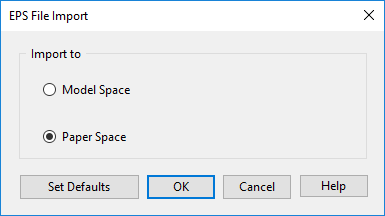 Import to: Choose whether the imported file will open in Model Space or Paper Space.
EPS Export Setup
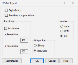
Explode Text: Explodes any text into its constituent parts. Save block as procedure: Saves the drawing's blocks as procedures in the PostScript language. Resolution: Sets the horizontal and vertical resolutions for the two-dimensional presentation of your drawing. Check Max Resolution to set the maximum 1600x1600 resolution. Output file: Exports to a binary or readable format. Header: Specify whether to include a preview image, and in what format.
FCW Import Setup
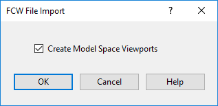 Create Model Space Viewports: Specify whether to create viewports for the Model Space presentation of your drawing.
FBX Import / Export
FBX loading and writing is totally automatic.
This file format now supports textures and materials.
GIF Export Setup
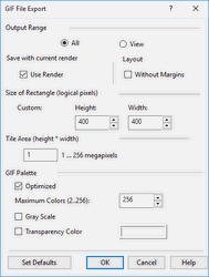
Optimized: Color palette optimization. If not checked, the initial color palette will imitate the Halftone palette, in which the color of a pixel is adjusted by mixing colors of adjacent pixels. If checked, the initial color palette will be optimized, containing no more colors than the number specified in the Maximum Colors field. Maximum Colors: Number of colors in the optimized palette (from 2 to 256). Grayscale: The initial color palette will contain shades of gray. Transparency Color: Sets the color that will be transparent. Available for the optimized palette. Layout - without Margins: Uses only the are within the margins to generate the GIF when the image is generated from a layout.
IGS Import Setup
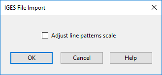
Adjust line pattern scale: Line style for improving line display. Because IGS files can be created in a variety of ways, either option (on or off) may work to improve precision during import.
JPG Export Setup
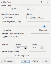
Output Range: Creates an export file either out of the entire drawing (All) or only the part that is currently in view (View). Use Render: Available only when Render or Hidden Line mode is active. If checked, the exported image will show the render displayed on the screen. JPEG quality factor: Your goal is generally to pick the lowest quality setting, or smallest file size, that decompresses into an image indistinguishable from the original. This setting can vary, but here are some rules of thumb. For good-quality, full-color source images, the default quality setting (Q 75) is very often the best choice. This setting is about the lowest you can go without expecting to see defects in a typical image. Try Q 75 first; if you see defects, then increase. If the image was less than perfect quality, to begin with, you might be able to drop down to Q 50 without objectionable degradation. On the other hand, you might need a higher quality setting to avoid further loss. This is often necessary if the image contains dithering or moire patterns. Except for experimental purposes, avoid values above Q 95; Q 100 will produce a file two or three times as large as Q 95, but with negligible quality improvement. Size of Rectangle: Sets the resolution for the exported graphics. By default, these values are 600 x 800 but you can customize the height and width Maximum resolution: The drawing will be defined by a rectangular matrix of 2000 x 2000 logical pixels. If there is at least one image object, this is set to 1000 x 1000.
Note: You can determine an object's type by using the Selection Info Palette.
OBJ Export Setup
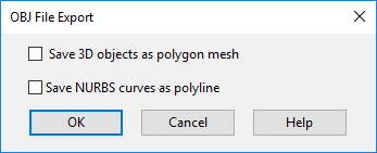 Save 3D objects as polygon mesh: When 3D objects are converted into a mesh, smoothness may be lost, but the exact appearance will be preserved.
Save spline curves as polyline: When NURBS curves are converted to polylines, smoothness will be lost, but the exact appearance will be preserved.
Save 3D objects as polygon mesh: When 3D objects are converted into a mesh, smoothness may be lost, but the exact appearance will be preserved.
Save spline curves as polyline: When NURBS curves are converted to polylines, smoothness will be lost, but the exact appearance will be preserved.
PDF Export Setup
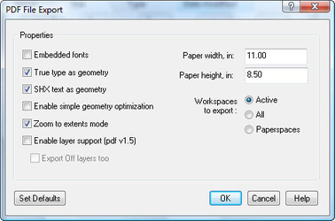
Embedded fonts: Fonts will be embedded in the PDF file, increasing the file size. If not checked, the PDF viewer (such as Adobe Reader) will select a font that exists in the system. True type as geometry: True-type text will be exploded into a collection of lines. SHX text as geometry: SHX text will be exploded into a collection of lines. Enable simple geometry optimization: When checked, smaller PDF files will be created. This may affect the PDF quality. Zoom to extents mode: Zooms into the closest point, showing the full model. Enable layer support (pdf v1.5): Add layers to the PDF. You can also opt to export Off layers as well. Workspaces to Export: Select Active to export only the active Space or All to export all Paper Spaces and Model Spaces. Paper Width: set the paper Width of the PDF. Paper Height: set the paper Height of the PDF.
PDF (Adobe PRC Based)
Export setup is fully automatic.
PDF (Adobe U3D Based)
Export setup is fully automatic.
Export named and standard views.
PNG Export Setup
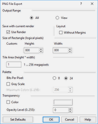 Bits Per Pixel: The number of bits per pixel in the saved image. A value of 8 means a 256-color palette; a value of 24 means True Color palette.
Gray Scale: The initial color palette will contain shades of gray.
Maximum Colors: Number of colors in the palette (from 2 to 256). Available if Bits Per Pixel = 8.
Color: Selection of transparency color. When Bits Per Pixel = 8, the pixels that have this color will be transparent. When Bits Per Pixel = 24, the pixels that have this color will get the level of opacity specified in the Opacity Level field. If Color is off, the level of opacity will be set for all pixels of an image.
Opacity Level: Level of opacity (alpha channel: from 0 to 255). Available if Bits Per Pixel = 24.
Bits Per Pixel: The number of bits per pixel in the saved image. A value of 8 means a 256-color palette; a value of 24 means True Color palette.
Gray Scale: The initial color palette will contain shades of gray.
Maximum Colors: Number of colors in the palette (from 2 to 256). Available if Bits Per Pixel = 8.
Color: Selection of transparency color. When Bits Per Pixel = 8, the pixels that have this color will be transparent. When Bits Per Pixel = 24, the pixels that have this color will get the level of opacity specified in the Opacity Level field. If Color is off, the level of opacity will be set for all pixels of an image.
Opacity Level: Level of opacity (alpha channel: from 0 to 255). Available if Bits Per Pixel = 24.
PLT Import Setup
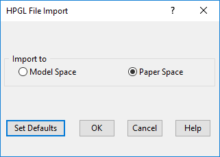 Import to: Choose whether to open the imported file in Model or Paper Space.
PLT Export Setup
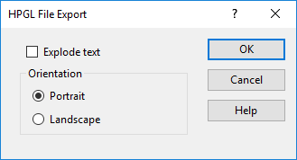 Explode text: Explodes any text into its constituent parts.
Orientation: Sets the paper orientation to Portrait (vertical) or Landscape (horizontal).
Explode text: Explodes any text into its constituent parts.
Orientation: Sets the paper orientation to Portrait (vertical) or Landscape (horizontal).
SAT Import Setup
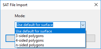
Mode: Choose one of the modes for representing SAT objects. Default: The choice of the polygon type is determined by the surface type in the solid object model (planar, cylindrical, spherical, toroidal, etc.) 3, 4, n-sided polygons: The number of sides of polygons used for object representation. If you wish to check what type of polygon is used for the object presented in an imported SAT file, do the following.
- Once the SAT file has been imported, select an object in the drawing, make a block of it, and bring this block onto the paper of the TurboCAD desktop.
- Open the Properties window for this block, open the Block Insertion page, and assign non-zero values to the rotation coordinates.
- When a 3D view of your object is displayed, select the object and explode it.
- After this, you can display individual elements (polygons) of the object by selecting the different parts of objects.
Existing ACIS SAT file import/export has been updated to support curves such as lines, arcs, circles, ellipses, and splines.
Previously in TurboCAD, ACIS file formats (SAT and SAB), only 3D objects were supported, along with their colors. However, now 2D entities allow the user to import the entire ACIS drawing. Geometry and Color are both supported for 2D entities.
SAT Export Setup
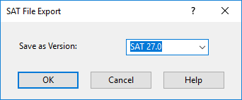 Select the SAT version for export.
SAB Import Setup
The Standard ACIS Binary (SAB) format is used by the ACIS modeling kernel from Spatial to share CAD data. Choosing SAB is especially beneficial when sharing with other ACIS based CAD systems where data is shared and not recalculated between different modeling kernels. TurboCAD supports both reading and writing SAB files.
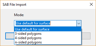
Mode: Choose one of the modes for representing SAT objects. Default: The choice of the polygon type is determined by the surface type in the solid object model (planar, cylindrical, spherical, toroidal, etc.) 3, 4, n-sided polygons: The number of sides of polygons used for object representation. If you wish to check what type of polygon is used for the object presented in an imported SAT file, do the following.
- Once the SAT file has been imported, select an object in the drawing, make a block of it, and bring this block onto the paper of the TurboCAD desktop.
- Open the Properties window for this block, open the Block Insertion page, and assign non-zero values to the rotation coordinates.
- When a 3D view of your object is displayed, select the object and explode it.
- After this, you can display individual elements (polygons) of the object by selecting the different parts of objects.
SAB Export Setup
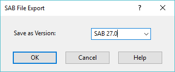
Select the SAB version for export.
SHX Export Setup
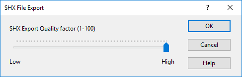
SHX Export Quality Factor: A high value creates shapes that more accurately represent the selected geometry. However, large values tend to create shapes that contain more coordinate data and can be a processing burden during regeneration. Low values create less accurate shapes that are more quickly processed. You may need to experiment with different values.
Note: SHX export does not create an *shx font file. Once created, the results cannot be edited.
STL File Export Setup
Binary: Saves to a binary file.
Color Binary: Saves to a color binary file. ASCII: Saves to an ASCII text file.
3D Print Check:
A new 3D Print Check option has been added when exporting an STL file. This tool checks part for the following common topological errors such as:
- non-manifold edges
- duplicate facets
- collapsed facets
- consistent normal orientation
- open edges
- shells
The tool also displays geometry information such as extents, number of facets/vertices, area, and volume. When saving an STL file, the user is given the option of performing a print check on the 3D model.

After saving the file, A dialog will appear for each object giving general information of the object as well as a result of 3D print tests. Please find the attached reference images.

WMF Import Setup
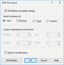
Prohibition of palette change: Prevents TurboCAD from changing the color palette. Insert to extents of: Sets the size of the imported drawing. View: The size is based on the current view. Drawing: The size is based on the entire drawing. Page: The size is based on the paper sheet. Custom: Define your own size. Custom extents: Enter coordinates and dimensions of the rectangle that encloses the drawing. Open in Model Space: Opens the imported drawing in Model Space. The drawing is placed on the default By World workplane.
WMF Export Setup
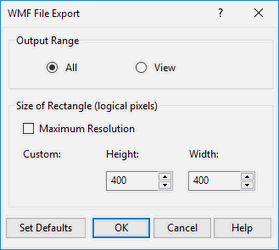 Output Range: Creates an export file either out of the entire drawing (All) or only the part that is currently in view (View).
Size of Rectangle: Sets the resolution for the exported graphics. By default, these values are 400 x 400 but you can customize the height and width
Maximum resolution: The drawing will be defined by a rectangular matrix of 8000 x 8000 logical pixels. If there is at least one image object, this is set to 1000 x 1000.
Output Range: Creates an export file either out of the entire drawing (All) or only the part that is currently in view (View).
Size of Rectangle: Sets the resolution for the exported graphics. By default, these values are 400 x 400 but you can customize the height and width
Maximum resolution: The drawing will be defined by a rectangular matrix of 8000 x 8000 logical pixels. If there is at least one image object, this is set to 1000 x 1000.
Note: You can determine an object's type by using the Selection Info Palette.
WRL Export Setup
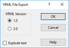 Select a version of VRML file to save. You can also explode the drawing text while creating the file for export.
3MF Export Support:
Now TurboCAD 2019 supports Export for the 3MF file type.
U3D Export Setup
1) Give an allow to control layer prefixes: Now each layer in U3d file has predefined prefix: "TCLayer_". User wants to change (edit) it. 2) Save drawing hierarchy in U3D file. In this case, Adobe pdf reader shows it.
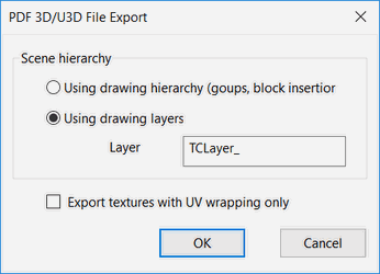
Export the drawing hierarchy into a U3D file (groups, block insertions):
-
User will have the ability to choose export the drawing hierarchy or layers into a U3D file.
-
User will have the ability to change the layer prefix.
-
This options will be available from the export setup dialog.
Following CAD Formats have been Improved
OBJ filter. Import materials
Added import RedSDK and Lightworks materials. Supported features: - diffuse color - transparency - reflection - texture map - bump map (RedSDK only) - reflection map (RedSDK only)
Support of Rhino 5 files (3DM) files
The latest openNURBS toolkit is incorporated to TurboCAD 2019.
SAT/SAB/IGES/STEP - Support for Interop Face Color
When reading ACIS objects (SAT/IGES/STEP/SAB import), if ACIS object has colored faces, then the appropriate material is assigned to these faces.
Import STEP format improvement
Import text attributes from a STEP file
User can access the text information and would like to read it out with VBA (TurboCAD-VBA-Object-Catalog) and store the text into the “Info” Property.
User can now view the information about the object used in the file. The information will be displayed in the ‘info’ field of “selection-info” palette.
Note : It supports both .STEP & .STP and .SAT files as well.
New IFC Object types now supported in TC2019
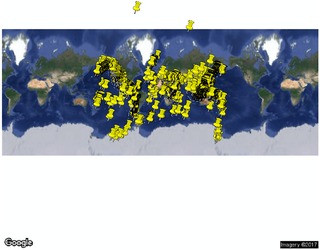
KMZ and KML
When a KMZ or KML file is imported it may include a Google map. Any data points will be represented by push-pin indicators which are purely a representation of the geolocation of the data point.
TurboCAD Formats
There are three TurboCAD file formats, TCW, TCT, and TCX, that you can use for saving vector graphics from within TurboCAD.
TCW: (TurboCAD for Windows) - a file format for saving vector graphics from within TurboCAD.
Note: If you need to save a drawing that is to be opened by an earlier version of TurboCAD, you can use Save As and save to one version back i.e. In TurboCAD 18 You can save as TurboCAD 17.
TCW, TCT Import Setup
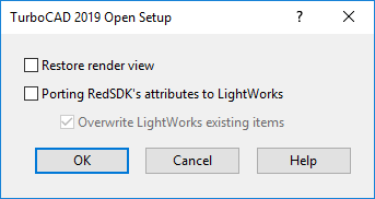 Restore render view: Opens the drawing in render mode. The file must have been saved in render mode.
TCW, TCT Export Setup
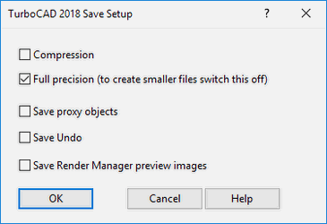
Compression: Saves the file in the TCT compressed format. If the speed of operation is more important than the file size, leave this option disabled.
Full Precision: TurboCAD stores your objects with the maximum possible accuracy. Full Precision enables the maximum depth of mathematical calculations performed to generate and save entities. When disabled, entities will be calculated and saved using only four decimal points of precision. This results in faster execution and smaller files but may compromise accuracy.
Note: Less than full accuracy can affect the ability of the program to correctly display and edit objects at extremely small scales. Unless you are using a slow machine, and know you do not need extreme accuracy, you should leave Full Precision on.
Save proxy objects: saves ACIS solids and a number of other TurboCAD Pro object with proxies so that TurboCAD Deluxe or Designer can open the file and see representations of objects that are not supported by those applications. Proxies increase the size of the file, but do allow file to open more quickly.
Save Undo: The Undo/Redo performed in the file are also saved when this option is enabled in setup while exporting.