Parametric Part Script Editing
(Available in Platinum)
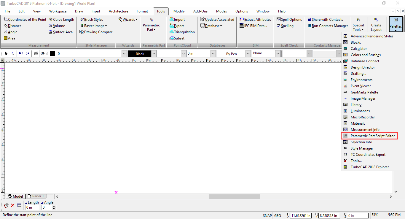
Default UI Menu: Tools/Palettes/Parametric Part Script Editor
Ribbon UI Menu:
Parametric parts (PPM) are defined using a text description (script). The script defines the structure, editable properties, and output that result in a parametrically editable part. The script must be saved with a *.PPM extension. The name of the file determines the name of the part.
Examining a Script
A simple example of a parametric part is a rectangle where the width, height and rotation angle are defined though parameters. The script of such part might look as follows: // Here is a description of simple rectangle. H = Parameter("Height", 5, LINEAR, Interval(0, 100)); L = Parameter("Length", 10, LINEAR, Interval(0, 200)); Angle = Parameter("Angle", 0, ANGULAR, Interval(0, 360)); Rect1 = Rectangle(H, L); Rect = RotateZ(Rect1, Angle); Output(Rect); Let's examine each line of this example: LINE 1 // Here is a description of simple rectangle. The '//' indicates a comment. Comments do not affect the behavior of a part. All text following '//' to the end of the line are contained by the comment. LINE 2 H = Parameter("Height", 5, LINEAR, Interval(0, 100)); The second line specifies the definition of the 'H' parameter. Let's break out each element of the line to define its function: H This is the identifier (name) of the parameter in the part description = The equals sign associates the identifier with its definition Parameter This is a function. 'Parameter' defines that H is a Parameter ( Specifies the start of the Parameter function's properties "Height" The name of the parameter that will appear in the Properties dialog , Indicates the end of one property and the beginning of the next 5 Assigns the default value for H , Separates properties LINEAR Specifies that H is a linear value , Separates properties Interval(0, 100) Specifies the allowable values for H as an interval from 0 to 100 ) Specifies the end of the Parameter function's properties ; End of definition for H LINES 3 – 4 L = Parameter("Length", 10, LINEAR, Interval(0, 200)); Angle = Parameter("Angle", 0, ANGULAR, Interval(0, 360)); The next two lines in the example are similar to the previous one. They define the characteristics of L and Angle parameters in a similar layout. Note that the 'Angle' parameter uses an ANGULAR interval rather than LINEAR. LINE 5 Rect1 = Rectangle(H, L); This line uses the Rectangle function to define a rectangle called 'Rect1'. It uses the previously defined H and L parameters to specify its properties, height and length. The center of this rectangle will be at the world origin (x=0,y=0,z=0) in the drawing. More on the rectangle tool will be covered later. LINE 6 Rect = RotateZ(Rect1, Angle); This line defines a new rectangle called 'Rect' which is a rotated version of 'Rect1', using the Angle parameter to define the rotation. LINE 7 Output(Rect); The last line specifies that the output of the script will be the rotated rectangle called 'Rect'. This is what the be drawn as the part.
Script syntax
The description of a parametric part consists of the entire contents of a text file, except comments, tabs, and other control characters, which are ignored. Comments are specified either using "//" characters that mean that all subsequent characters up to the end of the line are comments, or using the pair "/" and "/" that denote beginning and end of thecomment, respectively.
A text description is a set of two types of operators:
Identifiers
The
Expressions
Expressions define the associated identifier. Expression syntax matches the expression syntax in the majority of programming languages. They may define numeric value, arithmetic operations, the dependence of the defined object on other objects and function calls. The structure of a function call is:
),
Examples of correct expression syntax:
(D --1/4) * k;
Polyline(Point(0, 0.25 - 1/8), Point(0, D), Arc1(L-C, - m, m), Point(0,0));
A = B + 0.5;
B = 7;
Arithmetic Operations
Arithmetic operations may use the standard arithmetical operators '+' (addition), '--'(subtraction), '*' (multiplication), '/' (Division) and parenthesis '('and ')', to determine the sequence of performing arithmetic operations. Object identifiers and numbers serve as operands.
Script Semantics
A script contains full description of a parametric part. The collection of script operators determines which actions need to be performed to create the resultant object(s). Correct understanding of a script, requires having a clear understanding of how its operators are interpreted. Identifiers that are used in a
- A script may have more than one Output(..) operator, but any
should contained in only one Output(..) operator_._ - For each object used in the Output(..) operator there should be one, and only one, instance of any
. - For each object used in an
there should be one, and only one, instance of any . - Each identifier should be used only once as
- Each identifier should be at least once in an
operator or in an Output(..)operator_._ - Circular calculation and interdependent referencing are not allowed. The script must not contain interdependent where "Item One" is defined by "Item Two", and "Item Two" is defined by "Item One".
The following situations: A = B + 0.5; B = sin(A); or A = C+5; B = D+42; C = (3(2+A)); D = A/2; are not allowed. The first case A and B define each other directly. In the second case A is defined by B through C, and B is defined by A through D. This also means that an identifier is not allowed to depend on itself. For example, you cannot use an operator of this form: H = H1.05; NOTE: The sequence of script operators is not important (except certain special cases that will be described later); because operators are sorted before the script is run.
Basic Functions
Probably the most significant advantage of this method of creating parametric parts is the compact size and clarity of the text description of parametric parts in script form. The set of basic functions used in such a description, determines the level of clarity and simplicity of scripts for a particular class of parametric parts. Note: It is intended that the set of basic functions will expand from version to version.
Description of Parameters
It is important to understand the structure used to within a Parameter function.
Format:
| The name displayed in the user interface; | |
|---|---|
| The default value of the parameter; | |
| Defines the parameter type. The following example values are possible: LINEAR, means that the parameter is a linear value in the selected linear units of measure. ANGULAR, means that the parameter is an angular value in the selected angular units of measure. (only degrees are available at this time) TEXT, a text string; FONT, a font name; COLOR, an RGB color value; MATERIAL, a material name; CHECKBOX, a logical value, either ON or Off | |
| These are optional. They define possible restrictions imposed on parameters. Restrictions can be listed in arbitrary order and may take on the following forms: Set( |
Example of Parameter Description: Alpha = Parameter("Rotation Angle", 45, ANGULAR, Interval(-90, 90)); // This creates a parameter used to define a rotation angle. The name is 'Rotation Angle', the default is 45, the value type is ANGULAR, and the Interval is from '-90' to '90'
Functions for Creating 2D Entities
The following functions are used to create 2D graphic entities
Circle
The Circle function is used to create circles
Format: Circle(
| Defines the circle's radius | |
|---|---|
| Defines optional arguments that set the (x, y) coordinates of the circle center. By default, cx = 0, cy = 0 |
Example: N = Circle(D/2, 0, y0); A more extensive example: //circle.ppm – two circles r1 = Parameter("Radius1", 2.5, LINEAR, Interval(0.0, 10.0)); r2 = Parameter("Radius2", 1.25, LINEAR, Interval(0.0, 10.0)); xc = Parameter("CenterX", 3, LINEAR, Interval(-100, 100)); yc = Parameter("CenterY", 3, LINEAR, Interval(-100, 100)); c1 = Circle(r1); // circle centered on the origin c2 = Circle(r2, xc, yc); // circle offset from the origin Output(c1, c2);
Rectangle
The Rectangle function is used to create rectangles.
Format: Rectangle(
| Defines the rectangle width | |
|---|---|
| Defines the rectangle height | |
| Defines optional arguments that set the (x, y) coordinates of the rectangle center. By default, cx = 0, cy = 0 |
Example: rect = Rectangle(W, H, W/2. H/2); // Left bottom corner is in (0,0) point
Polyline
The Polyline function is used to create polylines consisting of straight line segments and arc segments.
Format: Polyline();
| Defines the list of arguments, delimited with commas. Arguments define individual segments of a polyline | |
|---|---|
A line segment is defined by 2 Points. An arc segment is defined with a Fillet function or with an Arc0 or Arc1 function and two Points on the ends of the arc. For polylines that contain only straight line segments, the consists of only 2D points, defined using Point(x,y) function.
Format: Point(
| Defines the x coordinates of the point | |
|---|---|
| Defines the y coordinates of the point |
For example, a rectangle can be defined in the following way:
rect = Polyline( // no end-of-line is used semicolon here Point(0,0), // since this function in on multiple lines Point(W, 0), Point(W,H), Point(0, H), Point(0,0) );
It should be noted that when a polyline's, first and last points are coincident, is called a closed polyline. This type of polyline bounds a certain area, and can be used for creating 3D objects. Polylines with arc segments are defined by adding auxiliary functions Arc0 and Arc1 to the list of arguments. Arc0 builds the circular arc clockwise, while Arc1 builds the circular arc counterclockwise.
Format: Arc0(
| Defines the x coordinates of the arc center | |
|---|---|
| Defines the y coordinates of the arc center |
The start and end point of an arc are defined by the preceding and the following arguments. Arc0 and Arc1 cannot be the first or last argument in the list of arguments. For a polyline that contains only one arc segment, the consists of 2 Points defined with Point(x,y) function and an arc defined with either the Arc0 or Arc1 function.
Example of arc0 and arc1 in a polyline:
//Polyarc.ppm – polyline with arcs YSize=5; XSize=6; R = 1; Path = Polyline(Point(0, R), // start at top of rounded lower left corner. Point(0, YSize-R), // go to bottom of rounded top left corner. Arc1(0, YSize, R), // make this corner a "cutout" Point(R, YSize), // left side of top edge Point(XSize-R, YSize), Arc0(XSize-R, YSize-R, R), // make this corner a "fillet" Point(XSize, YSize-R), Point(XSize, R), Arc0(XSize-R, R, R), // another fillet Point(XSize-R, 0), Point(R, 0), Arc1(0, 0, R), // another cutout Point(0, R)); Output(Path);
Another method of creating an arc in a polyline is to use the auxiliary function Fillet, which "smooths" two linear segments that start and end in the preceding point, by adding an arc with the specified radius into the corner. This ensures smoothness at the junction points.
Format: Fillet(
| Defines the radius of the fillet | |
|---|---|
Example of fillets in a polyline: // polyfillet.ppm – polyline with fillets H = 5; L = 10; FR = 1; p2 = Polyline(// Rectangle with rounded corners Point(0,0), // lower left corner Point(L,0), // lower right corner Fillet(FR), // places fillet at bottom right Point(L,H), // upper right corner Fillet(FR), // places fillet at top right Point(0,H), // upper left corner Fillet(FR), // places fillet at top left Point(0,0), // closes rectangle Fillet(FR) // fillets start/end corner. Since this is a closed shape, // no following Point function is needed. ); Output(p2); Fillet and Arcs can be used together in the same Polyline function. Example of Arcs and Fillet in a polyline: Poly1 = Polyline( // Rectangle with rounded corners Point(0,0), Point(W - r, 0), Arc1(W - r, r), Point(W, r), Point(W, H - r), Arc1(W - r, H - r), Point(W – r ,H), Point(0, H), Fillet(r), Point(0,0), Fillet(r) );
Functions for Creating 3D Entities from 2D Entities
You can use 2D entities as the basis for creating 3D objects.
Thickness
The Thickness function creates a 3D entity based on the 2D entity by adding thickness. It also allows you to change the thickness property of the 3D object. Format: Thickness(
| Defines the initial graphic object | |
|---|---|
| Defines new value of Thickness |
Example of Thickness: RectA = Rectangle(2, 5); RectThick = Thickness(RectA, 3); Example of Thickness Used to Create a Box Function: Input(x0,y0,z0,x1,y1,z1) R = Rectangle(x1-x0, y1-y0, (x0+x1)/2, (y0+y1)/2); T = Thickness(R, z1-z0); Output(Move(T, 0, 0, z0)); Another Example of Thickness: //thickrect.ppm – draws a 2D rectangle and adds thickness L = Parameter("Length", 4, LINEAR, Interval(0.1, 20)); W = Parameter("Width", 3, LINEAR, Interval(0.1, 20)); H = Parameter("Height", 1.5, LINEAR, Interval(0.1, 20)); Rect = Rectangle(L, W); Box = Thickness(Rect, H); Output(Box); An Example of Thickness with a Circle: // thickcircle.ppm – draws a circle and adds thickness Cylind=Thickness(Circle(1,2,2),2); Output(Cylind); An Example of Changing Thickness: // thickcircle2.ppm – draws a cylinder and changes thickness Cylind=Thickness(Circle(1,2,2),2); Cyl2 = Thickness(Cylind, 4); // changes the thickness of the first cylinder Output(Cyl2);
Sweep
The Sweep function creates a 3D object by extruding a specified profile along a path, defined by a 2D polyline or circle. The profile is defined by a closed 2D polyline or circle.
Format: Sweep(
| This defines the profile using a 2D polyline | |
|---|---|
| This defines the path, along which the profile is "dragged"; the path is defined by a 2D polyline Note: The plane of the path and the plane of the profile must not be parallel. | |
| This optional argument, defines the rotation angle of the profile relative the Z axis; by default, the argument is equal to zero |
Example of Sweep: Poly1 = Polyline( Point(0,0), Point(1, 0), Point(1,2), Point(0, 2), Point(0,0) ); PolyProfile = RotateX(Poly1, 90); // the Rotate function will be explained later PolyPath = Polyline( Point(0,0), Point(10, 0), Point(10,10), Point(0, 10), Point(0,0) ); PolySweep = Sweep(PolyProfile, PolyPath); Output(PolySweep); Another Example of Sweep //sweep1.ppm R = 2; D = 5; C1 = RotateX(Circle(R, D/2+R, 0),90); // profile C2 = Circle(D/2, 0, 0); // path Torus = Sweep(C1,C2); Output(C1, C2, Torus); //C1 and C2 shown for reference An Extended Example of Sweep //sweep2.ppm – another sweep example L = Parameter("Length", 5, LINEAR, Interval(0.005, 1000)); W = Parameter("Width", 3, LINEAR, Interval(0.005, 1000)); H = Parameter("Height", 1, LINEAR, Interval(0.1, 3)); FR = Parameter("Fillet Radius", 0.3, LINEAR, Interval(0.001,100)); p = Polyline(Point(0,0), Point(0,H), Point(-FR,H), Point(-FR,0), Point(0,0)); p1a = RotateX(p,90,0,0); p1 = Move(p1a, 0, W/2, 0); p2 = Polyline( Point(0,0), Point(0,W), Fillet(FR), Point(L,W), Fillet(FR), Point(L,0), Fillet(FR), Point(0,0), Fillet(FR)); s = Sweep(p1, p2); Output(s);
Functions for Creating 3D Entities Directly
3D object may also be created directly without reference to a 2D entity.
Sphere
The Sphere function is used to create a 3D sphere.
Format: Sphere(
| This value specifies the radius of the sphere | |
|---|---|
| These are optional argument used to specify the x, y, z location of the sphere's center point. By default the values for these argument is zero |
Sphere Example: SR1 = Sphere(10,1,3,5.5); Another Sphere example: //sphere.ppm – simple sphere example R = Parameter("Radius", 2.5, LINEAR, Interval(0.01, 20)); cx = Parameter("CenterX", 0, LINEAR, Interval(-100, 100)); cy = Parameter("CenterY", 0, LINEAR, Interval(-100, 100)); cz = Parameter("CenterZ", 0, LINEAR, Interval(-100, 100)); S = Sphere(R, cx, cy, cz); Output(S);
Cone
The Cone function is used to create a 3D cone.
Format: Cone(
| This value specifies the height of the cone | |
|---|---|
| This value specifies the radius for the base of the cone | |
| This optional argument specifies a radius for the top of the cone, creating a truncated cone. By default the value for this argument is zero |
Cone Example: CN1 = Cone(10,5,2); Another Cone Example //cone1.ppm – a simple cone R = Parameter("BaseRadius", 0.5, LINEAR, Interval(0.01, 10)); H = Parameter("Height", 3, LINEAR, Interval(0.05, 20)); Cone1 = Cone(H, R, 0); Output(Cone1); Example of a Truncated Cone: //cone2.ppm – a truncated cone R1 = Parameter("BaseRadius", 0.5, LINEAR, Interval(0.01, 10)); R2 = Parameter("TopRadius", 0.1, LINEAR, Interval(0, 10)); H = Parameter("Height", 3, LINEAR, Interval(0.05, 20)); Cone2 = Cone(H, R1, R2); Output(Cone2);
Functions for Transforming Geometric Objects
This class of functions is used for moving, and rotating geometric objects. These transformations are related to the transformation of the coordinate system. As always functions create transformed objects, while original objects do not change.
Move
The Move function is used to move (shift) graphic objects. Format: Move(
| Defines the original graphic object | |
|---|---|
| Defines value of movement along x, y and z axes, respectively | |
| Defines the number of created objects, where each subsequent object is created by moving the preceding object; this argument is optional, with the default value of 1 |
Example of Move: PolyProfile = Move(Poly1, 1, 3); Another Example: //move.ppm – illustrates the Move function RB = Parameter("BaseRadius", 2, LINEAR, Interval(0.1, 10)); RT = Parameter("TopRadius", 0.5, LINEAR, Interval(0, 10)); H = Parameter("Height", 4, LINEAR, Interval(0.1, 20)); con1 = Cone(H, RB, RT); cx = Parameter("CenterX", 5, LINEAR, Interval(-10, 10)); cy = Parameter("CenterY", 0, LINEAR, Interval(-10, 10)); cz = Parameter("CenterZ", 0, LINEAR, Interval(-10, 10)); count = Parameter("Copies", 2, LINEAR, Interval(1, 10)); con2 = Move(con1, cx, cy, cz, count);// create count copies, offsetting each by cx, cy, cz Output(con1, con2);
Rotate
The RotateX, RotateY. RotateZ functions are used to rotate graphic objects around the X, Y and Z axes, respectively. Format: RotateX(
| Defines the original graphic object | |
|---|---|
| Defines the angle of rotation | |
| Sets an offset for the rotation axis relative to the X, Y and Z axes (in accordance with function names). These arguments are optional; however, only all three arguments can be omitted at once. Default value for each of |
|
| Defines the number of created objects, where each subsequent object is created by transforming the preceding object; this argument is optional, with the default value of 1 |
Example of Rotate: PolyProfile = RotateX(Poly1, 90); Another Example of Rotate: //rotate.ppm – demonstrates the rotate functions c1 = Circle(2, 10, 0); // create a circle c2 = RotateX(c1, -90, 0, 0); // rotate the circle to lie in the XZ plane c3 = Move(c2, 0, -0.05, 0); // move it back half the thickness c4 = Thickness(c3, 0.1); c5 = RotateZ(c4, 30, 0, 0, 11); //duplicate the circle by rotating about the Z axis c6 = Circle(2, 0, 10); c7 = Move(c6, 0, 0, -0.05); c8 = Thickness(c7, 0.1); c9 = RotateX(c8, -30, 0, 0, 11); c10 = Circle(2, 0, 0); c11 = RotateZ(c10, -90, 0, 0); c12 = Move(c11, 10, 0, -0.05); c13 = Thickness(c12, 0.1); c14 = RotateY(c13, 30, 0, 0, 11); Output(c4, c5, c8, c9, c13, c14);
Functions for Loading External Symbols as Elements
You can load non-parametric external symbols from external files to be a part of a parametric part. The files must be importable (supported) by the CAD system, such as .TCW, .DWG, *.SKP
StaticSymbol
The StaticSymbol function loads non-parametric symbols from external files. When the external symbol's filename is specified with no path information, the symbol is automatically assumed to reside in a sub-folder named Macro that is located in the ppm file's home folder.
Format: StaticSymbol(
| Defines the file name with extension. If the extension is not specified, native file format will be used | |
|---|---|
| This is an optional argument, which indicates that only the block with the given name should be used as the symbol for loading, and the rest of the contents should be ignored; if the argument is not defined, the active drawing will be loaded as a symbol |
Example of StaticSymbol: //staticsym1.ppm – loads an external file from the Macro sub-folder S = StaticSymbol("ExternalSymbol.tcw"); Output(S); //static symbol from ExternalSymbol.tcw file is inserted on the drawing
Set(FolderList(...))
To create a list of files in a folder, Set(FolderList(...)) is typically used as the Parameter restriction.
Format:
| Defines the path to the folder from which the list of files will be created | |
|---|---|
| Defines the mask of file names and extensions |
Example of Set(FolderList(..)): // staticsym2.ppm – loads an external symbol from a different folder than Macro DrawingName = Parameter("Drawing", "Drawing1", Set(FolderList("......\Drawings", ".tcw")));//quantity of "....\" (before folder Drawings) is equal to quantity //of steps over folder tree starting from the Macro sub-folder. S0 = StaticSymbol("......\Drawings\"DrawingName".tcw"); //here a static symbol is loaded from a file with a tcw-extension, // and a filename picked from the FolderList obtained via the DrawingName parameter. Output(S0); When specifying a relative path, you must remember that the path is always assumed to start, not at the folder that contains the ppm file, but in a folder below that named "Macro". In the example above, assume for the moment that staticsym2.ppm is located in: C:\Users\Me\Documents\MyCAD\PPM Documentation Samples The path used in the FolderList path and the StaticSymbol path must then implicitly begin at C:\Users\Me\Documents\MyCAD\PPM Documentation Samples\Macro The external symbol is being loaded from: C:\Users\Me\Documents\MyCAD\Drawings That means the script must navigate up three directories to the MyCAD folder, then back down one level to the Drawings folder, so the correct relative path is: ......\Drawings Another example, which loads a specific .tcw file from the Drawings folder: //staticsym3.ppm – loads a specific file from a different folder S = StaticSymbol("......\Drawings\3DSliceTest.tcw"); //only loads the specific file 3DSliceTEst.tcw. //Remember that the relative path is still rooted in the Macro subfolder. Output(S); A parametric part (a file with a .ppm extension) can loaded by calling the name of the parametric file as if it were a function, whose arguments are the parameters of the part to be loaded, in the order in which they are described in the file. Refer to "Creating Custom Functions" below for more details on this process.
Functions for 3D Boolean Operations
Functions of this class are used to perform Boolean operations on 3D geometric objects.
BooleanUnion
The BooleanUnion function creates an object by adding the specified objects together. Format: BooleanUnion(
| Defines an object to be used in the Boolean operation. There must be at least two objects | |
|---|---|
Example of BooleanUnion: S1 = Sphere(5); S2 = Sphere(5,5,5); S3 = Sphere(5,5,-5); S4 = Sphere(5,-5,5); S5 = Sphere(5,-5,-5); S6 = BooleanUnion(S1,S2,S3,S4,S5); Output(S6); Another Example: R = Parameter("Radius", 8, LINEAR, Interval(0.001, 1000)); s = Sphere(R); c = Circle(R/3); c1 = Thickness(c, R*2); c2 = Move(c1, 0, 0, R); //Cylinder s1 = BooleanUnion(s, c2); //Sphere with cylinder Output(s1);
BooleanSubtraction
The BooleanSubtract function creates an object by subtracting the secondary objects from the primary object.
Format: BooleanSubtract(
| Defines an object to be used in the Boolean operation. There is only one primary object | |
|---|---|
| Defines a secondary object to be subtracted from the primary object There must be at least one or more secondary objects |
Example of BooleanSubtract: S1 = Sphere(5); S2 = Sphere(5,5,5); S3 = Sphere(5,5,-5); S4 = Sphere(5,-5,5); S5 = Sphere(5,-5,-5); S6 = BooleanSubtract(S1,S2,S3,S4,S5); Output(S6); Another Example of BooleanSubtract: R = Parameter("Radius", 8, LINEAR, Interval(0.001, 1000)); s = Sphere(R); c = Circle(R/3); c1 = Thickness(c, R*2); c2 = Move(c1, 0, 0, -R); //Cylinder s1 = BooleanSubtract(s, c2); //Sphere with hole Output(s1);
BooleanIntersect
The BooleanIntersect function creates an object derived from the intersection of the primary and secondary objects. Format: BooleanIntersect(
| Defines an object to be used in the Boolean operation. There must only two objects | |
|---|---|
Example of BooleanIntersect: S1 = Sphere(5); S2 = Sphere(5,5,5); S3 = Sphere(5,5,-5); S4 = Sphere(5,-5,5); S5 = Sphere(5,-5,-5); S6 = BooleanIntersect(S1,S2); Output(S6);
Functions for Modifying 3D Objects
Several functions are available to modify the geometry of 3D objects.
Fillet Edges
The Fillet Edges function allows rounding one or multiple edges of 3D object. Format: G3Fillet(
| Defines the 3D object whose edges are to be rounded | |
|---|---|
| Defines the edge or multiple edges, which are to be filleted. Each edge is defined by Point(xc,yc,zc) or Array of Points. Point(xc,yc,zc) is the middle point of an edge to be filleted (for example in the TurboCAD "Fillet Edges" operation, this point is marked with a blue square). Array of Points defines a set of edges to be filleted. | |
| Defines the Fillet radiuses. Fillet radiuses are set by Array function. For a single edge the Array contains pair of values, for multiple edges - multiple pairs of values. |
Fillet Edges Example: Array(Point(x1,y1,z1), Point(x2,y2,z2), Point(x3,y3,z3)); //defines 3 edges for filleting //Point(x1,y1,z1), Point(x2,y2,z2), Point(x3,y3,z3); – 3 middle points on 3 edges to be filleted Another Example: Array(r1, r2)-- //array of radius values for rounding the selected edge. It defines rounding //radiuses for 2 ends of the selected edge. //r1 – start radius of fillet //r2 – end radius of fillet. Example of Filleting 1 Edge: G3Fillet(PartA,Point(xc,yc,zc), Array(r1, r2)); //where Point(xc,yc,zc) - middle of the edge. Another Example: Door= G3Fillet(Door0, Point(0, -1, (Height-FHeight-4-3/4)/2), Array(1, 1)); For example (fillet of 1 edge of the box): x = Parameter("size", 5, LINEAR, GreaterThan(0)); r1 = Parameter("r1", 1, LINEAR, GreaterThan(0)); b0 = Box(0, 0, 0, x, x, x); b1 = G3Fillet(b0, Point(x/2, 0, 0), Array(r1, r1*2)); Output(b1); Example of Filleting 4 Edges of a Box: L = Parameter("Length", 5, LINEAR); W = Parameter("Width", 3, LINEAR); H = Parameter("Height", 1, LINEAR); R = Parameter("Radius",0.5); g0 = Box(0,0,0,L,W,H); g1 = G3Fillet(g0, Array(Point(L/2, 0, 0), Point(0, W/2, 0), Point(L/2, W, 0), Point(L, W/2, 0)), Array(R, R, R, R, R, R, R, R)); Output(g1);
Chamfer Edges
The Chamfer Edges function allows chamfering any edge or multiple edges of 3D object. Format: G3Chamfer(
| Defines the 3D object whose edges are to be chamfered | |
|---|---|
| Defines the edge or multiple edges, which are to be filleted. Each edge is defined by Point(xc,yc,zc) or Array of Points. Point(xc,yc,zc) is the middle point of an edge to be filleted (for example in the TurboCAD "ChamferEdges" operation, this point is marked with a blue square). Array of Points defines a set of edges to be chamfered. | |
| Defines the Chamfer distances. These are set by Array function. For a single edge the Array contains a pair of distance values, for multiple edges - multiple pairs of distance values. |
A Chamfer Example: Array(d1, d2)-- //array of 2 offset values at the ends of an edge. Another Example: Door= G3Chamfer(Door0, Point(0, -1, (Height-FHeight-4-3/4)/2), Array(1, 1)); //Here Door0 -is the object whose edge is to be chamfered. //Point(0, -1, (Height-FHeight-4-3/4)/2) – indicates this edge. //Array(1, 1) sets 2 chamfer distances Another Example: x = Parameter("size", 5, LINEAR, GreaterThan(0)); r1 = Parameter("r1", 1, LINEAR, GreaterThan(0)); b0 = Box(0, 0, 0, x, x, x); b2 = G3Chamfer(b0, Point(x/2, x, x), Array(r1, r1+r1)); Output(b2);
G3Offset
The G3Offset function extends a solid face inward or outward. Format: G3Offset(
| Defines the 3D object whose edges are to be extended | |
|---|---|
| Defines the face, which is to be extended. The Face is defined by a Point(x,y,z) belonging to this face | |
| Defines the offset distance. A positive value will offset the face outward, and a negative value will offset inward |
Offset Example: G3Offset(PartA, Point(xf, yf, zf), dist); Where: PartA — is the 3D object whose faces are to be offset Point(xf, yf, zf) — is a point for selecting the face to be offset dist — is the value of face offset Another Example: x = Parameter("size", 5, LINEAR, GreaterThan(0)); r1 = Parameter("r1", 1, LINEAR, GreaterThan(0)); b0 = Box(0, 0, 0, x, x, x); b3 = G3Offset(b0, Point(x,x/2,x/2), r1/2); Output(b3);
G3Shell
The G3Shell function allows shelling the shape of solid object, leaving the selected face open. It creates a shell of a specified thickness from a single solid object. The new faces are created by offsetting existing faces inside or outside. Format: G3Shell(
| Defines the 3D object whose edges are to be shelled | |
|---|---|
| Defines the face that should remain open. It is defined by the Point(xc,yc,zc) function which describes a point belonging to this face | |
| Defines the shell thickness. A positive value creates an outward shell, and a negative value creates an inward shell |
Shell Example: G3Shell(PartA, Point(xf, yf, zf), thickn); Where: Part3 — selects the object which is to be shelled Point(xf, yf, zf) — is the point on the face, which should remain open thickn — is the shell thickness Another Example: L = Parameter("Length", 5, LINEAR); W = Parameter("Width", 3, LINEAR); H = Parameter("Height", 1, LINEAR); T = Parameter("Thickness", 0.2, LINEAR); g0 = Box(0,0,0,L,W,H); g1 = G3Shell(g0, Point(L/2, W/2, H), T); Output(g1); //After inserting a shelled object in the drawing, shell thickness can be edited in the Selection Info palette (as well as Length, Width and Height parameters)
G3Bend
The G3Bend function is used for bending 3D objects. Format: G3Bend(
| Defines the 3D object which is to be bent | |
|---|---|
| Defines a line about which the solid object will be bent. It is defined by 2 Points: Point(x1, y1, z1), Point(x2, y2, z2). The line must lie on the solid face selected for bending. | |
| Defines the bending angle. The angle is measured from the plane of the bent face. | |
| Defines the bending radius | |
| Defines the Neutral Depth to set the distance into the depth of material along which there will be no tension or compression |
Bend Example: G3Bend(Part3, Point(x1, y1, z1), Point(x2, y2, z2), Angle, R, 0); Another Example: P1=Thickness(Rectangle(10,20),3); B0 = G3Bend(P1, Point(3, 3, 0), Point(3,8,0), 90, 2, 0); Output(B0);
Setting and Changing Object Properties
The SetProperties function is used to set the properties of objects. Format: SetProperties(
| Defines the object to be used as the base for the new object with set properties | |
|---|---|
| Defines the name of the property to be set. The name should be surrounded with quotation marks | |
| Defines the value to be assigned to the property |
Example of SetProperties: BlueRect=Rectangle(10,5); RedRect = SetProperties(BlueRect, "PenColor" = 0xff, "PenWidth" = 0.2); Output(RedRect); Another Example: Side2M = SetProperties(Side2, "Material" = "Wood\Pine", "PenColor" = 0xff); Another Example: PL1 = SetProperties(PL0, "Brush" = "SOLID"); Another Example: SetPlastic = ("Material" = "Plastics\Plain white"); BoxMaterial = SetProperties(MyBox,SetPlastic); In the Parametric Part manager there is a special tool to choose the required value for such properties as Material, Pen Color and Brush Style. To activate it, right-click on the property name. This will open the Local Menu either for Material table or PenColor table or BrushStyle table. The appropriate table will appear where the desired value can be chosen.
Nesting Functions
Functions can be nested within a single expression to optimize scripting efficiency. For Example: BF = BooleanSubtract(B1,Move(RotateZ(RotateY(Box(-5,-5,-5,5,5,5),45),45),-1,-1,-1)); Example Used in a Small Script: B1 = Box(0,0,0,10,10,10); BF = BooleanSubtract(B1,Move(RotateZ(RotateY(Box(-5,-5,-5,5,5,5),45),45),-1,-1,-1)); Output(BF);
Functions for Creating Text
Text
The Text function defines the text string itself and its characteristics, including fonts, style, effects, etc. Acceptable font values are dependent upon those installed on your machine.
Format: Text(
| Defines the text string. Text string can be specified either directly here (with quotation marks) or via an identifier of text object | |
|---|---|
| Defines the text font | |
| Defines the text style |
Example: bsb = Text("BS(b)", Tfont, Tstyle);
TextFont
The TextFont function sets the text font, size, and the angle of text line location.
Format: TextFont(
| Defines the mode of the text: Standard (when mode=0) or Scalable (when mode=1 or any other value different from 0) | |
|---|---|
| Defines the text font size | |
| Defines the angle of text line | |
| Defines the text font |
Example: Tfont = TextFont(0,2, 45, "Arial"); Where: 0 — means that text is Standard 2 — text height 45 — text line is located at 45 degrees Arial — font
TextStyle
The TextStyle function sets the text style including justification, text effects and styles.
Format: TextStyle();
| Defines the text characteristics separated with commas. The following values of characteristics are allowed: For Justification: LEFT, CENTER, RIGHT, TOP, MIDDLE, BASELINE, BOTTOM For Text Effects: BOX, UNDERLINE, STRIKETHROUGH, AllCAPS For Style: BOLD, ITALIC | |
|---|---|
Example: Tstyle = TextStyle(LEFT, TOP, UNDERLINE); Another Example: //Standard text of Times New Roman font with 5in of font size, //with Left,Top justification, with TextBox effect, Bold, Italic, at 45 degrees of Angle ht=5; font_name = "Times New Roman"; Tfont = TextFont(0, ht, 45, font_name); Tstyle = TextStyle(LEFT, TOP, BOX,BOLD, ITALIC); bsb = Text("BS(b)", Tfont, Tstyle); Output(bsb);
Auxiliary Functions
Extents
The ExtentsX1, ExtentsX2, ExtentsY1, ExtentsY2, ExtentsZ1 and ExtentsZ2 functions are used to calculate the extents of graphic objects. Format: ExtentsX1(
| Defines the object to be used | |
|---|---|
The presence of X, Y or Z characters in the function name determines axis along which the extents will be calculated. 1 or 2 index--indicates whether minimum or maximum value should be calculated. Example of Extents: xmin = ExtentsX1(PartA); xmax = ExtentsX2(PartA); ymin = ExtentsY1(PartA); ymax = ExtentsY2(PartA); zmin = ExtentsZ1(PartA); zmax = ExtentsZ2(PartA); P1 = Box(xmin, ymin, zmin, xmax, ymax, zmax); Another Example of Extents: A0=Thickness(Rectangle(H-3/4,D), 3/4); A1=RotateY(A0,90); xmin = ExtentsX1(A1); xmax = ExtentsX2(A1); ymin = ExtentsY1(A1); ymax = ExtentsY2(A1); zmin = ExtentsZ1(A1); zmax = ExtentsZ2(A1); P1 = Box(xmin, ymin, zmin, xmax, ymin+3, zmin+4);
ParameterPoint
The ParameterPoint function defines a parametric point with number and coordinates.
Format: ParameterPoint (
| Defines the number of the parametric point | |
|---|---|
| Defines the coordinates of parametric point |
Example of ParameterPoint: P0 = ParameterPoint(0, l, -l, 0); P1 = ParameterPoint(1, 0, 0, 0);
PointX, PointY, PointZ functions
The PointX, PointY, PointZ are used to calculate the coordinates of parametrical point. The PointX function calculates X-coordinate of parametrical point. The PointY function calculates Y-coordinate of parametrical point. The PointZ function calculates Z-coordinate of parametrical point.
Format: PointX (
| Defines the parametrical point from which the X or Y or Z coordinate will be extracted | |
|---|---|
Examples of Point: x0 = PointX(P0); // x0=1 for P0 = ParameterPoint(0, l, -l, 0); y1 = PointY(P1); //y1=0 for P1 = ParameterPoint(1, 0, 0, 0); z1 = PointZ(P1); //z1=0 for P1 = ParameterPoint(1, 0, 0);
Special functions and operators
IF
The IF function allows various actions to be performed depending upon whether the specified condition is fulfilled or not fulfilled. It plays the role of a conditional operator, and can be used to create branches in the logic of building a parametric part.
Format: IF(
| Defines the condition under test using the following comparison operations: == (equal) < (less than) > (greater than) <= (not greater than) >= (not less than) | |
|---|---|
| Defines the value of the IF function when the value of |
|
| Defines the value of the IF function when the value of |
IF Example: A = IF(L >= H, Rectangle(L, H), Rectangle(H, L)); //Regardless of the specified size of L and H, the created rectangle A will be positioned //horizontally (the longer side will be along the X axis). / In this example "Rectangle(L, H)" is the TRUE result and "Rectangle(H, L" is the FALSE result. / Another Example: Tstyle = IF(dir > 0, TextStyle(MIDDLE, RIGHT), TextStyle(MIDDLE, LEFT)); //Regardless of the specified size of dir, Text Style will be specified with Right or Left justification.
UNITS
The UNITS function defines the units that will be used in the script. It defines the System, Space Units and Scale of dimensions used while creating objects. This function allows loading parts correctly in drawings with different specified units.
Format: Units(
| Defines object scale | |
|---|---|
| Defines the units in the English or Metric systems |
Units (1[in]) — this means that the main units of measurement are inches. It is possible to use other units for some particular values even when the entire drawing is created with the default unit. In order to use millimeters for particular values while inches are default units, you can explicity declare the desired unit for these values. For Example: Units(1[in]);// means that default unit of drawing is inches Units(1[mm]);// means that default unit of drawing is millimeters For example, you can use value M=5[mm]; and Units(1[in]) in the same script. It means that only M value is measured in mm while all others are measured in inches. Moreover, this function allows for scaling the created objects down (when N<1) or up (when N>1). For Example: Units(2[in]);//created object is scaled up 2 times compared with the case of Units(1[in]); Units(0.5[in]);// created object is scaled ½ as large as compared with the case of Units(1[in]);
RefPoint
The RefPoint function sets the location of the Reference Point for the parametric part. When the Reference Point is one of the output values of a script, it is inserted in the drawing along with the part. This enables precise insertion of the parametric object into the drawing.
Format: RefPoint(
| Defines the (x,y,z) coordinates for location of Reference Point | |
|---|---|
For Example: xArrow = PointX(P0); yArrow = PointY(P0); rf = RefPoint(xArrow, yArrow, 0); //-> RefPoint is placed on the point (xArrow,yArrow, 0) Output(rf);
Input and Output
The Input and Output functions are used for inputting initial values or objects into the script and outputting result objects from the script.
Format: Input(); Output(
);
| Defines the list of variables or objects for input or a list of results for output | |
|---|---|
For Example: Input(H, W, D, A, Dis); Output(SideA_L,Bottom_B,Back_I, Face1, FalseD1, E1,E2,E3,E4, N1, T1, Door, FF, SideA_R); Example of the Output with Conditional Output: Sw = Parameter("Switch", 1, CHECKBOX); P1 = Thickness(Rectangle(5,5), 3); S1= Thickness(Circle(2.5),4); Output(IF(Sw,P1,S1)); //Here is either cylinder or box inserted on the drawing //depending on checkbox Sw value
min and max
The min and max functions are used for choosing the minimum or maximum values within a set of values.
Format: min(
| Defines the set of numerical values, identifiers of variables or Array of variables | |
|---|---|
For Example: r=min(2,5,1,7,9);//r=1 R=max(2,5,1,7,9);//R=9 For Example: A=2; B=5; C=1; D=7; E=9; A1=2; B1=5; C1=1; D1=7; E1=9; r=min(A,B,C,D,E);//r=1 R=max(A1,B1,C1,D1,E1);//R=9 Example of using Array of Values: A=2; B=5; C=1; D=7; E=9; r=min(Array(A,B,C,D,E));//r=1
Note: A Group of objects cannot be used as argument of these functions, because a Group is a collection of graphic objects, rather than a collection of numbers.
Mod
The Mod function is used for finding the remainder of the integer division. For example, Mod(5,4) is 1, because 5/4 = 1, with a remainder of 1. Mod(7,4) is 3, because 7/4 = 1, with a remainder of 3. Mod(7,3) = 1, because 7/3 = 2, remainder 1. Note: The Mod function is often used to determine if a number is odd or even, because Mod(AnyOddNumber, 2) = 1, while Mod(AnyEvenNumber, 2) = 0.
Format: Mod(
| Defines the expression or identifier that represents the dividend | |
|---|---|
| Defines the expression or identifier that represents the divisor |
For Example: A = 7; B = 4; C = Rectangle(A, Mod(A,B)); Output(C);
Div
The Div function is used to perform division.
Format: Div(
| Defines the dividend | |
|---|---|
| Defines the divisor |
For Example: A=7; B=3; result1 = A/B; result2 = Div(A, B); rect = Rectangle(result1, result2) Output(rect);
Additional Math Functions
sqrt
Calculates the square root of a specified number P = sqrt(b);
asin
Calculates the arcsine. Returns the angle in radians P = asin(0.5);
acos
Calculates the arcsine. Returns the angle in radians P = acos(0.5);
Array
The Array function defines an array of values, or an array of Points, by directly listing the elements of the array. In other words the Array function collects geometric objects or values into an Array object.
Format: Array()
| list of numerical values or geometric objects An | |
|---|---|
For Example: Array(Point(L/2, 0, 0), Point(0, W/2, 0), Point(L/2, W, 0), Point(L, W/2, 0)) // It is the array of points defining the edges for G3Fillet. Array(R, R, R, R, R, R, R, R) //It is the array of radius values for filleting the array of edges. Another Example: Can txt = Parameter("text", "Simple text example", TEXT); a = Array(TextFont(0,10,"Arial"), TextStyle(CENTER, MIDDLE, ITALIC)); //Array of 2 items: TextFont and TextStyle) s0 = Text(txt, a); Output(s0);
Group
The Group function collects multiple graphic objects into a group and assigns an identifier name to the result. It allows the script to work with multiple objects as if they were a single object. Also a Group can be the output value of a script. Groups of objects can take part in different operations: Move, Rotate, etc.
Format: Group ();
| Defines the list of graphic objects, separated with commas. The | |
|---|---|
For Example: bse = Group(bse_below, bse_above); //group of 2 graphic objects Br2 = Group(Br0, Br1); For Example: Bx = Group(Move(BxL, -Dis1.5), Move(BxR, Dis1.5)); ShelfFBx = BooleanSubtract(ShelfF, Bx); Output(ShelfFBx, Bx);
Special Functions without Parameters
PI
The PI function calculates the value of Pi = 3.14159...
#$AUX@_Contour
Defines a clipping contour for the resulting object. This is used to clip (remove) sections of walls when the object in inserted into a wall. It uses a referenced contour that is defined elsewhere in the script. The referenced contour must be closed. For Example: contour = Polyline(P10, Arc0(PointX(C1), PointY(C1)), P11, Arc0(PointX(C2), PointY(C2)), P12, Arc0(PointX(C3), PointY(C3)), P13, P03, P00, P10); contourZ = RotateX(contour, 90); ClipContour = SetProperties(contourZ, "#$AUX@_Contour" = 1,"PenColor"= 0x0000ff); TS = RefPoint (W/2, 0, -elevation); Output(ClipContour, TS);
Creating custom functions
When scripts of the same type are created, which describe a particular class of parametric parts, it can be convenient to have the sequence of repeated actions as a separate specialized function. To achieve this, the repeated actions can be put into a separate );
For Example:
Input(x0,y0,z0,x1,y1,z1);
The Output operator should also be defined.
Format:
Output(
);
A custom function created in this manner must be placed in a Macro folder, which is always located inside the folder of the calling script. When the custom function is used, the script's file name (without the .ppm extension) is used just as if it was a built-in function.
Format:
)
Below is an example of a custom function. The file box.ppm can be found in the PPM Documentation Samples/Macro folder:
// box.ppm – defines a custom Box function. // The custom function is called in this way: // B = Box(Xmin, Ymin, Zmin, Xmax, Ymax, Zmax); // The function creates a 3D box with given min/max values Input(x0,y0,z0,x1,y1,z1); R = Rectangle(x1-x0, y1-y0, // Rectangle with Xmin = x0, Xmax= x1 (x0+x1)/2, (y0+y1)/2); // Ymin = y0, Ymax = y1 T = Thickness(R, z1-z0); // depth = Zmax - Zmin Output(Move(T, 0, 0, z0)); // move result along z to Zmin The script below is box blend.ppm, which calls the custom function box.ppm _//box_blend.ppm uses the custom Box.ppm function in the Macro folder. x = Parameter("size", 5, LINEAR, GreaterThan(0)); r1 = Parameter("r1", 0.5, LINEAR, GreaterThan(0)); b0 = Box(0, 0, 0, x, x, x); b1 = G3Fillet(b0, Point(x/2, 0, 0), Array(r1, r1*2)); Output(b1);
File location is crucial when using parametric scripts as custom functions. In the example above, if blend_box.ppm lies in the folder D:/Symbols, then it can only find the box.ppm script if box.ppm is located in the folder D:/Symbols/Macro.
Parametric Parts Reserved Word List
| PI | LINEAR | TEXT |
|---|---|---|
| ANGULAR | MATERIAL | FONT |
| COLOR | CHECKBOX | ITALIC |
| BOLD | UNDERLINE | BOX |
| ALLCAPS | STRICKETHROUGH | TOP |
| MIDDLE | BOTTOM | BASELINE |
| LEFT | CENTER | RIGHT |
| Call | Array | + |
| - | * | Div |
| Mod | / | - |
| sin | cos | tan |
| atan | min | max |
| ** | = | == |
| != | < | > |
| <= | >= | & |
| Solid | Extrude | |
| UNIQUE | GraphicId | VertexId |
| Vertex | Face | |
| Edge | Source | Bound |
| Intersect | OperationList | BlendArg |
| BlendParam | BlendType | BlendRadiusMode |
| BlendSetback | BlendRadiusBlendSmooth | BlendRadiusParam |
| BlendOffsetParam | BlendFaceEntity | BlendFaceEdge |
| BlendFaceVertex | BlendEdgeEdge | BlendEdgeVertex |
| BlendEdgeVertexMain | BlendEdgeVertexAux | ShellArg |
| ShellThickness | ShellFace | ShellEdge |
| FaceEditArg | Transform | ScaleX |
| ScaleY | ScaleZ | ShearXY |
| ShearXZ | ShearYZ | RotateX |
| RotateY | RotateZ | TranslateX |
| TranslateY | TranslateZ | Path |
| Profile | LateralFace | LateralEdge |
| CapFace | CapEdge | JointEdge |
| Profiles | HighLight | FaceMaterialArg |
| FaceMaterial | FaceOffsetArg | FaceHoleArg |
| FaceHole | BendId | BendRadius |
| BendAngle | BendNeutral | BendFlag |
| BendPosition | BendFlangeHeight | BendAxialDistance |
| BendAzimuthAngle | BendEdgeStartPosition | BendEdgeEndPosition |
| Face2FaceLoftArg | Face2FaceLoft | |
| AssemblyAxis | Input | Output |
| Include | Units | StaticSymbol |
| FolderList | Macro | Parameters |
| Parameter | ParameterPoint | PointX |
| PointY | PointZ | Set |
| Interval | LessThan | GreaterThan |
| LessOrEquail | GreaterOrEqual | Circle |
| Rectangle | Polyline | Point |
| Arc0 | Arc1 | Fillet |
| IF | Move | Thickness |
| Sweep | Cone | BooleanUnion |
| BooleanSubtract | BooleanIntersect | G3Fillet |
| G3Chamfer | G3Shell | G3Offset |
| G3Slice | G3Bend | ExtentsX1 |
| ExtentsX2 | ExtentsY1 | ExtentsY2 |
| ExtentsZ1 | ExtentsZ2 | Text |
| TextFont | TextStyle | Group |
| SetProperties | PatternCopy |
Example PPM Symbol
 The following code will generate a window. To use the resulting window you must either:
- Save the script as a .ppm file, and load the folder containing the file into the symbol library, and then drag the symbol onto a wall.
- Run the PPM script. Select the result, and turn it into a block. Finally drag the block from the block palette onto a wall.
3ArchWindow.ppm
Units(1[mm]); H = Parameter("Window Height", 1200, LINEAR, Interval(400, 10000)); W = Parameter("Window Width", 2000, LINEAR, Interval(700, 10000)); Curvature = Parameter("Curvature", 40, LINEAR, Interval(0, 100)); elevation = Parameter("Window Eleveation", 700, LINEAR, Interval(0, 10000)); sash = Parameter("Window Sash", 30, LINEAR, Interval(0, 100)); W1 = W/3.0; P00 = Point(0,0); P10 = Point(0, H); P11 = Point(W1, H); P12 = Point(2W1, H); P13 = Point(3W1, H); P03 = Point(3W1, 0); C1 = Point(0.5(PointX(P10) + PointX(P11)), 0.5(PointY(P10) + PointY(P11)) - Curvature); C2 = Point(0.5(PointX(P11) + PointX(P12)), 0.5(PointY(P11) + PointY(P12)) - Curvature); C3 = Point(0.5(PointX(P12) + PointX(P13)), 0.5*(PointY(P12) + PointY(P13)) - Curvature); contour = Polyline(P10, Arc0(PointX(C1), PointY(C1)), P11, Arc0(PointX(C2), PointY(C2)), P12, Arc0(PointX(C3), PointY(C3)), P13, P03, P00, P10); contourZ = RotateX(contour, 90); ClipContour = SetProperties(contourZ, "#$AUX@_Contour" = 1, "PenColor"= 0x0000ff); TS = RefPoint (W/2, 0, -elevation); Output(ClipContour, TS); PL = Point(sash/2, H); PR = Point(W1 - sash/2, H); ArcWind1 = Polyline(Point(sash/2, 0), Point(sash/2, H), Arc0(PointX(C1), PointY(C1)), Point(W1 - sash/2, H), Point(W1 - sash/2, 0), Point(sash/2, 0)); ArcWindz1 = RotateX(ArcWind1, 90); ArcWind2 = Move(ArcWind1, W1, 0, 0); ArcWindz2 = RotateX(ArcWind2, 90); ArcWind3 = Move(ArcWind2, W1, 0, 0); ArcWindz3 = RotateX(ArcWind3, 90); ArcWindz1D = Thickness(ArcWindz1, sash); ArcWindz1Surf = SetProperties(ArcWindz1D, "Solid" = 0); ArcWindz2D = Thickness(ArcWindz2, sash); ArcWindz2Surf = SetProperties(ArcWindz2D, "Solid" = 0); ArcWindz3D = Thickness(ArcWindz3, sash); ArcWindz3Surf = SetProperties(ArcWindz3D, "Solid" = 0); contourZ3D = Thickness(contourZ, sash); contourZ3DSurf = SetProperties(contourZ3D, "Solid" = 0); res1 = BooleanSubtract(contourZ3DSurf, ArcWindz3Surf); res2 = BooleanSubtract(res1, ArcWindz2Surf); res3 = BooleanSubtract(res2, ArcWindz1Surf); Output(res3);