Cursor Movement Options
This section covers two ways you can constrain cursor movements - orthogonal mode and angle constraints.
Orthogonal Mode
Menu: Options / Orthogonal Mode
Shortcut Key: H
Toolbar Icon:
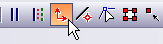
Constrains consecutive points in drawing commands so that the alignment of a pair of points is parallel to the X, Y, or Z axis. If you try to set points that are not aligned parallel to one of these axes in Orthogonal Mode, DesignCAD automatically shifts the second point of the pair so that the points are aligned parallel to the nearest matching axis.
Angle Constraint Mode
Toolbox Icon:
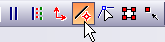
Restricts point placement in drawing commands to a specified set of angles from the previous point. The set of angles used may be set using the Angle Constraint Settings Command.
Activate Angle Constraint Mode. Select a drawing command and set a beginning point. Set the number of points required or desired to draw the entity. Angle Constraint Mode will remain active until the command is selected again to turn it off.
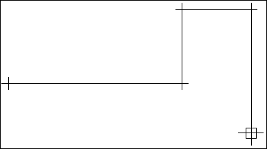
Example: Draw a line with segments at 0, 30,90, 150, 180, 210, 270, or 330 degrees.
Activate Angle Constraint Mode. Select the Line command and set a point on the screen. Move the cursor around slowly. Notice that the rubber-band line only moves in one of eight directions. Set a point for the body of the line. Slowly move the cursor around. Again, notice that the rubber-band line only moves in one of eight directions. Set another point. Press Enter to complete the command and add the line to the drawing.
Angle Constraint Settings
Menu: Options / Angle Constraint Settings
Used to change the settings used in Angle Constraint Mode.
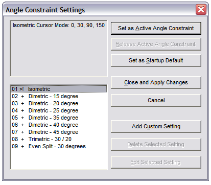
Set as Active Angle Constraint: Sets the selected set of angle constraints as the current one.
Release Active Angle Constraint: Disables all angle constraints.
Set as Startup Default: Makes the current set of angle constraints the default set. The next time you load the program, you won’t have to load this set of angle constraints to use them. They will be used when Angle Constraint Mode is enabled.
Close and Apply Changes: Closes the window. DesignCAD is ready to use the selected set of angle constraints as the current one.
Cancel: Closes the window. DesignCAD is ready to continue using the set of angle constraints that was being used before the window was opened.
Add Custom Setting: Opens a window that lets you add sets of custom angle constraints.
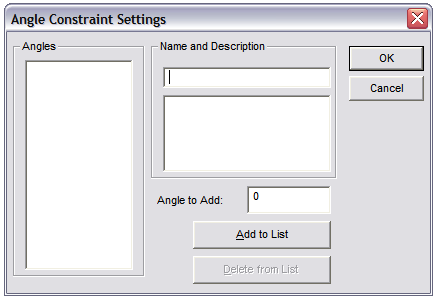
- Angles: A list of the angles that will be used in the new set of angle constraints.
- Name and Description: The name and description that will be used for the new set of angle constraints.
- Angle to Add: Enter an angle in this box and then click on the Add to List button to add it to the angle constraint set.
- Delete from List: Removes the selected angle measurement from the list of angles in the Angles area.
Delete Selected Setting: Deletes the currently selected set of angle constraints. Only custom sets of angle constraints may be deleted.
Edit Selected Setting: Opens the currently selected set of angle constraints so that it may be edited. Only custom sets of angle constraints may be edited.