Lines
This section covers methods for creating various types of lines and curves.
NOTE: Certain properties of lines and curves can be changed in the Info Box.
Double Line Mode 
Menu: Options / Double Line Mode
Toolbar Icon:
When simple 2D lines and curves are drawn in Double Line Mode, DesignCAD draws two parallel entities at the same time. Double Line Mode simplifies several common types of drawings, including house plans and land plots.
The Double Line Toolbar controls where and how the parallel entities are drawn.
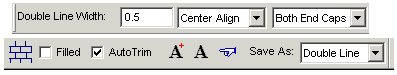
Double Line Width: Sets the width of the entity (the amount of space between the two parallel entities) in Drawing Units.
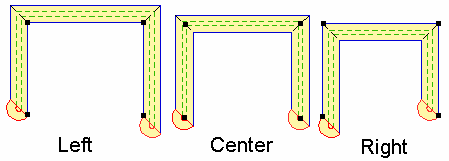
Align: Select Center, Left, or Right to set the position of the width of the double entity. If Left is selected, the width of the entity will extend to what would be your left if you were standing on the first point set for the entity facing the second point set for the entity.
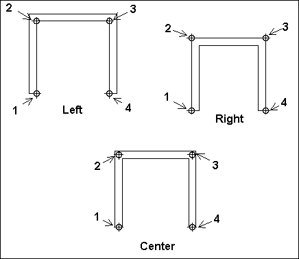
NOTE: If the double entity is drawn with the Left or Right option, you will be able to snap to both sides of the finished double entity. If the double entity is drawn with the Center option selected, you will be able to snap to both sides and the center of the double entity.
Cap: Specify which ends of the double entity are capped or left open.
Fill Pattern Setting: Select a hatch pattern with which to fill the entity. The Filled option must be checked for the hatch pattern to be used.
Filled: Draws a filled entity, otherwise the double line will be hollow.
Auto Trim: Automatically trims the entity where it overlaps itself or another double entity.
NOTE: The Explode command can be used to explode a double entity into vectors. If you are going to cross one double entity over another, explode the existing double entity and uncheck the Auto Trim box before drawing the second double entity to ensure that all four entities will be visible in the intersection.
Apply to Selected Double Lines: Applies the current options to selected double entities in the drawing.
Apply to All Double Lines: Applies the current options to all double entities in the drawing.
Same As: Match the parameters of an existing double entity. Click on the double entity already in the drawing that has the properties you want to assign to the options in the Double Line bar.
Save As: Select Double Line, Plane, or Line to determine how the entity will be recognized and saved in the drawing.
NOTE: You can convert existing entities to double- line entities..
MultiLine Mode 
Menu: Options / MultiLine Mode
Toolbar Icon:
When separate 2D lines, curves, arcs, circles, and ellipses are drawn in Multiline mode, DesignCAD simultaneously draws a set of parallel objects.
The same operations as those permitted for Double Line objects are also available for multiline objects. In essence, Multiline Mode is Double Line Mode with advanced capabilities for setting line representation.
When Multiline Mode is active, the created 2D lines, curves, arcs, circles, and ellipses are displayed as multiline objects, with the current multiline style used.
Creating Multiline Styles
Menu: Options / Multiline style
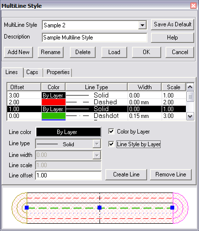
Multiline Style lists all multiline styles available in a given document. The Selected element of the list corresponds to the style that DesignCAD uses to draw a new 2D object in Multiline mode. This style is considered the current style.
Each multiline style has a name and description. The name is specified at the time of creation, and can be changed by the user. Styles can have identical names. Style description is optional, and can be used, for instance, to specify more precisely the purpose and particular details of using a given style.
Add New: is used for adding a new style. When you add a new style, you need to enter its name and description (if desired). The new style will have the current settings for Lines, Caps, and Properties. Thus, to create a new style you can select an existing one, and change it as desired. There can be a maximum of 64 styles for one drawing.
Rename: is used to change the name of the current style.
Delete: is used to remove the current style.
Load: is used to load styles from a file. Multiline styles can be loaded from any .dcd file created in DesignCAD. After clicking Load you can select the file which contains the required styles in the Load Multiline Styles window (Open* button).
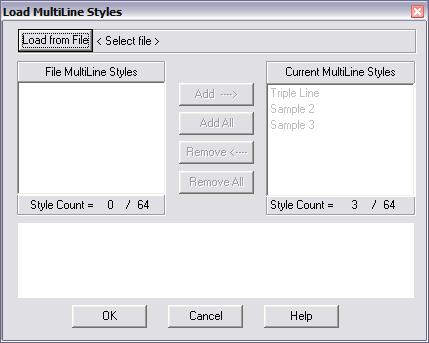
The list under the button (on the left) will show all multiline styles that exist in the file. To transfer a style into the current document, use Add and Add All buttons; to cancel the transfer use the
Remove and Remove All buttons. These buttons work only for the styles added from the list on the left. Existing styles cannot be removed using this window.
To specify the default multiline style, you can use Save As Default button. When this button is pressed, the currently selected style becomes the default style, and the entire list of styles is copied to the file Multiline.sys. The list of styles stored in this file is used as the starting set of multiline styles when a new document is created.
The default style, as well as Triple Line style that is the first in the list of styles, cannot be deleted.
Lines page
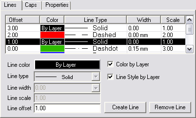
This page contains all settings for positioning lines relative each other, and controlling their display properties (color, style, width, scale).
All information about lines used in the current multiline style is presented in the spreadsheet. Offset is used as the parameter for sorting.
After selecting a line in the spreadsheet, the user can edit its properties and settings.
Line Color: defines the line color. When the Color by Layer flag is set, DesignCAD will use the color of the object’s layer.
Line Type: defines the line type. Here you can choose one of the types available in DesignCAD.
Line width: line width (in millimeters). This width does not depend on document scale, and always stays the same. It is similar to Fixed Lineweight for single lines and curves.
Line Scale: scale applied to the selected line type. When the Line Style by Layer flag is set, the type, width and scale of the line will match those specified for the layer where the object is located.
Line Offset: relative offset of lines, which determines the distance between them. The offset is calculated from a certain 0 axis, in DesignCAD’s current scale units. For example, if a style uses 4 lines, the first of which has offset equal to 2, and the fourth equal to 8, the apparent width of the line will be 6.
To add a line to the line style, select an empty row in the spreadsheet, set the line properties, and press the Add Line button.
To delete a line, select it, and press the Remove Line button. Note that each multiline style must have at least 1 line defined; therefore you cannot remove all lines from the linestyle.
Caps page
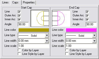
Defines shape, style, and color of lines for caps. There are separate settings for start and end of a multiline.
Line flag: when this flag is set, the corresponding boundaries (start or end points) of the first and last lines are connected with a line.
Outer Arc flag: when this flag is set, the corresponding boundaries (start or end points) of the first and last lines are connected with an arc.
Inner Arc flag: when this flag is set, all boundaries of internal lines (between the first and the last one) are connected in pairs, with arcs. The pairs are formed from the lines on opposite sides,
e.g. the second line is connected with the next to last one.
Angle field: determines the tilt angle of the cap. The angle is calculated from the lower line. The angle is specified in degrees, from 0 to 180. It is used only for multilines. For other multiline objects, it is automatically set at 90 degrees.
Properties page
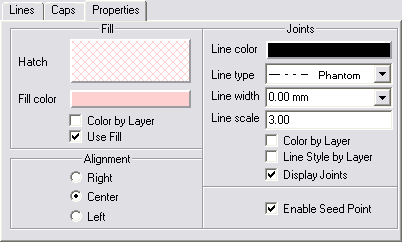
This page contains all other settings for multiline style.
Fill: contains the following settings for multiline object fill:
Hatch: defines the style, scale and tilt angle of the fill.
Fill color: defines the color of the fill.
Color by Layer: when it is specified, the color of the layer, where the multiline object was created, will be used for the fill.
Use Fill: determines whether fill will be used.
Enable Seed Point: links fill to a point. When this flag is set, the fill will be displayed the same all the time, regardless of line position and operations performed with it.
Alignment: settings for aligning a multiline object.
Joints: settings for representation of line inflection points.
These settings are used only for multilines; they are turned off automatically for all other multiline objects.
Display Joints: when this flag is set, a straight line (with color and style specified by above mentioned settings) will be drawn between the points on the 1st and last lines, corresponding to the point on the multiline object (except the 1st and last points, because the caps are drawn there).
Editing Multilines
To change the multiline style of the current multiline object, you can invoke its Info Box (see “Info Box” on page 178), and click Change Style. In this case, all operations for adding,removing, and loading styles will be inaccessible. The Multiline style list will contain an additional style: the name of one of existing styles with the word (Current) appended to it. This is the style that is currently used to display the selected object.