Texture Mapping

NOTE: Patterns such as Cells, Brick, and Perlin noise contain more complex options.

Menu: Tools / Texture Mapping
You can add more patterns, if you like.
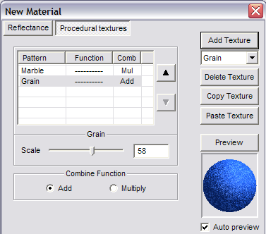
The up and down arrows can be used to change the order of patterns. You can remove a pattern by highlighting it and selecting Delete Texture. You can also Copy and Paste patterns to create new ones, within the same material.
When the pattern or combination of patterns is defined, click OK. The material will then appear in the Material list.Applies a texture from an image file (bitmap, gif, jpeg, etc.) to one or more surfaces. You can combine an image with one of the materials defined in the materials list .The next time the drawing is shaded using either Gouraud (Medium Quality) or Phong (Best Quality) method in the Shading Command all items that have been assigned a texture will be shaded accordingly.Several jpegs are included with DesignCAD as sample textures and are located in the DesignCAD folder.
These options are available for Texture Mapping:
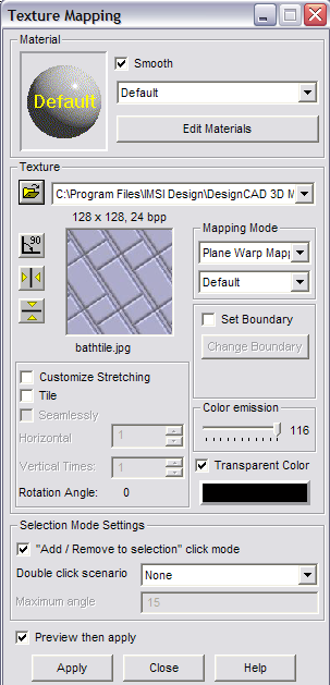
Material: If you want to combine a material with the image, select a material from the list. Otherwise, leave “Default.” To edit or create materials, click Edit Materials.
Texture: Click the Browse icon to locate the image file. The images you select are added to the drop-down list, so you can easily find them later.
Rotate 90º: Rotates the image file 90 degrees for the image’s use as a texture. This button can be used two times to rotate the image 180 degrees and three times to rotate the image 270 degrees.
Mirror Horizontally: Flips the image so that all portions of the image that were on the left side will now be on the right and vice versa.
Mirror Vertically: Flips the image so that all portions of the image that were on the top of the image will now be on the bottom and vice versa.
Customize Stretching: Allows for the customization of the image’s scale and aspect ratio.
Tile: Places repeated copies (or an array) of the image appear on a single surface. When this option is selected:
Seamlessly: Inverts one image everywhere two images meet, so the edges of the image copies will not be as noticeable.
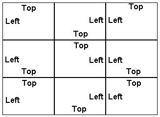
Image Scale: Enter the value for the scale at which the image is to be displayed. For example, a value of .5 will display the image at half of its original size and a value of 2 will display the image at two times its original size.
Aspect Ratio: The relationship of the vertical and horizontal scale factors at which the image is to be displayed. For example, a value of .5 will display the image so that the vertical scale is twice that of the horizontal scale, and a value of 2 will display the image so that the horizontal scale is twice that of the vertical scale.
Horizontal Times: Enter the number of copies of the image to be displayed from left to right on the selected item(s).
Vertical Times: Enter the number of copies of the image to be displayed from top to bottom on the selected item(s).
Rotation Angle: This value displays the current rotation angle of the image being used as a texture. This value can be increased or decreased by clicking the Rotate 90 button repeatedly.
Mapping Mode: The default direction for the texture runs parallel to the Y axis; this direction can be changed for some of the Mapping Modes. Each Mapping Mode has a unique set of options available in the list box directly below the Mapping Mode list box. Each Mapping Mode and option combination works best with a different kind of entity. Some experimentation may be required to determine which Mapping Mode and option works the best for different items in a given drawing.
-
Spherical Mapping: As its name indicates, this particular mode works best on rounded 3D surfaces. Unlike most of the other Map- ping Modes, Spherical Mapping mode has a single method: Center. Spherical Mapping mode takes the flat image and wraps and stretches it around the selected object. The direction for the texture determines the “poles” of the object. If the Y axis is said to run through the poles of the object, the top and bottom edges of the image are compressed to meet at these poles and are stretched to fit around the “equator” of the object.
-
Grid Patch Mapping: Divides the image into the number of surfaces the selected object has. Each division of the image is then assigned to a surface. This mode is recommended for items that have a flat face but have been extruded into a 3D object or “grid.” This mode has two methods: Grid Only and Grid & Plane.
-
Grid Only: Maps the selected texture to the “depth” or “grid” portion of the object (the portion of the object that is not the front “face”).
-
Grid & Plane: Maps the selected texture to both the “face” and “grid” of the object.
-
Box Mapping: Uses a bounding box to map the texture to the selected objects. The bounding box is an invisible box that com- pletely surrounds the selected objects. The front and back of this box run parallel to the XY plane. The left and right sides of this box run parallel to the YZ plane.
The top and bottom of this box run parallel to the XZ plane.
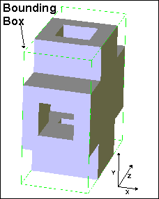
This mode has six methods. Each of these six methods corresponds to a different side of the bounding box. The texture is placed parallel to the specified side of the bounding box and then projected onto the selected object(s).
-
- Cylindrical Mapping: As its name indi- cates, this particular mode works best on cylindrically-shaped objects. Unlike most of the other Mapping Modes, Cylindrical Map- ping mode has a single method: Center Axis. Cylindrical Mapping mode takes the flat im- age and wraps it around the selected object. The direction for the texture determines the “poles” of the object. If the Y axis is said to run through the “poles” of the object, the im- age is compressed to meet at these “poles.”
-
Plane Warp Mapping: This Mapping Mode should only be used on plane entities. Plane Warp Mapping mode has two methods. De- fault method maps the entity using as much of the image as possible without causing a substantial amount of distortion, the Set Boundaries and Change Boundaries options can be used so the entire image is used. The Cutoff method trims away portions of the im- age so that it has the same shape as the plane to which it is to be applied.
-
-
- Default: When this method is chosen, two options appear below it: Set Boundaries and Change Boundaries. The Set Boundaries op- tion can be checked to make the entire image be used when the drawing entity is mapped. The perimeter of the plane is calculated and the points on the plane that make the most sense mathematically are set as the four cor- ners for the texture. The Change Boundaries button can be used to allow four points to be set in the drawing to reset the four corners of the texture.
- Cutoff: The Cutoff method of Plane Warp Mapping trims away portions of the image so that it has the same shape as the plane to which it is to be applied. The direction of the texture may be set in the Rotate box.
-
Color emission: If set to zero, the image completely covers the base material color (but not the pattern). If it is set to 100, then the material color and texture color are blended equally
Transparent Color: The color selected here will be transparent when applied.
Add / Remove to selection click mode: If checked, clicking a surface or object will toggle whether or not it is selected.
Double click scenario: Determines what happens when you double-click an object or surface.
Example:
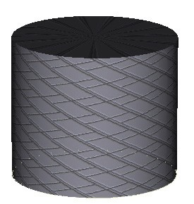
Draw a cylinder and open the Texture Mapping window. Select the cylinder face.
For Texture, select something from the “Sample Textures” folder, and use Cylindrical mapping.
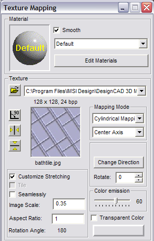
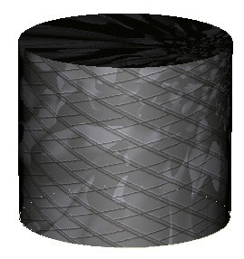
Click Apply to cover the cylinder with the texture.
To combine this texture with a material, select a material (“Marble” in this case).
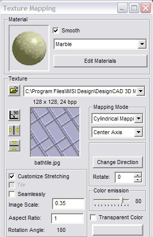
Click Apply again to see the change. Adjust the Color emission to control how much of the materials shows relative to the texture image.