Drafting Palette Toolbar
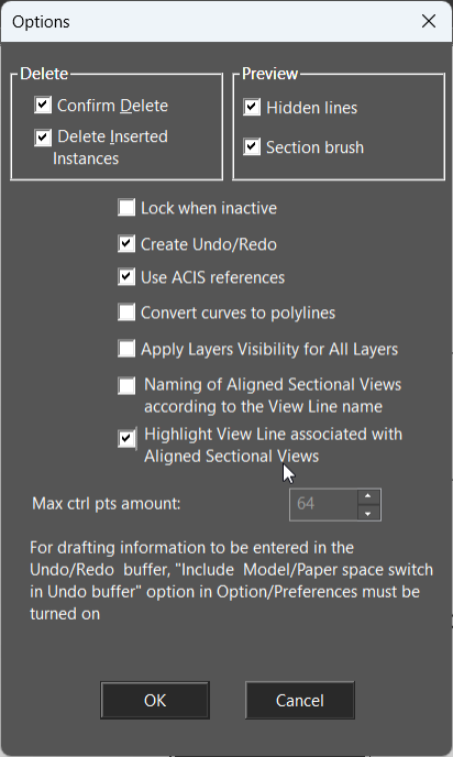
 Create Part / Assembly: Enables you to define a part or a combination of parts (assembly) for creating views. See Parts and Assemblies Delete: Deletes the selected part, assembly, or view. Rename: Renames the selected part, assembly, or view. Add: Adds the selected standard view that appears in the bottom of the palette to the view list at the top of the palette. Insert into Drawing: Inserts the view selected from the view list into the drawing. (You can also drag the name from the list into the drawing to insert a view.) Create by View Line: Creates a sectional view from an existing view, by using an existing line or polyline as the section line. Fragmental View: Creates a Fragmental view (breakout) of a specific part of section or view. Breaks: Breaks are used to reduce the lengths of objects which will not fit into the drawing. Drafting Palette Options: Contains options for deleting objects and what appears in view previews.
Layer Set: Different layer sets could be selected for the drafting palette objects.
Lock When Inactive: When selected Drafting palette objects will not refresh while the Drafting palette is closed.
Create Undo/Redo: Add changes to Drafting Palette objects to the Undo/Redo history. Use ACIS references: Defines that the controlling geometry for dimensions and insertions will be ACIS referred for ACIS-based Drafting palette objects. Convert curves to polylines: Curves in the Drafting palette objects will be displayed as polylines. This increases processing speed but minutely decreases accuracy. Naming of Aligned Sectional Views according to the View Line name: . The View Line name is reflected in the name of Aligned Sectional View. Highlight View Line associated with Aligned Sectional Views: The line highlights in the drawing space. Max ctrl pts: Specifies the maximum number of polylines that will contain for any curve section. The lower half of the palette contains standard views. The top row contains orthographic and isometric views and the bottom row contains sectional views. 
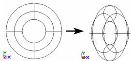
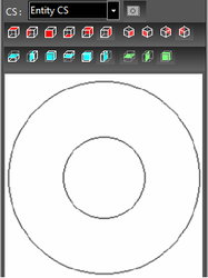
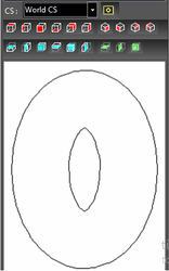
Entity CS, World CS: Sets the view based on one of these coordinate systems. As an example, a torus is created and rotated about the Y axis.

With Entity CS, the Plan view looks down on the torus in its own CS, even though the torus is rotated.  With World CS, the Plan view looks down on the rotated torus.