3D Mesh

(Available in Platinum, Professional and Deluxe)
Default UI Menu: Draw/3D Object/3D Mesh
Ribbon UI Menu:

Creates a mesh that represents a set of facets. The base of a mesh is a rectangle with the sides parallel to the X and Y axes.
Note: The Terrain tools provide another way to create a meshed surface. See Terrain
To create this mesh, TurboCAD defines a matrix consisting of X and Y nodes, with each node separated by a Step value. The default number of nodes is 14 for each axis, but this can be changed in the Inspector Bar. In addition, you can specify Interpolation nodes, which are nodes created between the main X and Y nodes. If you use interpolation nodes, Z values are interpolated between main nodes, thus creating a smoother mesh.
- In the Inspector Bar, enter the number of nodes and interpolation nodes. If you know the Step value, you can enter that as well.
- Place the rectangular mesh by selecting a corner point. If the Step values are not defined, sizing the rectangle will establish them. Notice that the interpolation nodes do not appear yet.
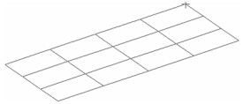
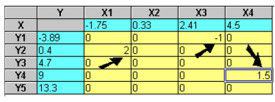
- A coordinates table appears, in which you can enter Z values for each X-Y node. In this table, you can also modify the position of X and Y mesh lines, but you cannot edit X and Y coordinates of individual nodes at this stage of creating the mesh.
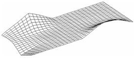
- Click OK. The mesh now contains the interpolation nodes, and the Z values are linear interpolations between the main X-Y nodes.
 -
-
Tip: Use the Edit Tool to move a single node or a group of nodes. 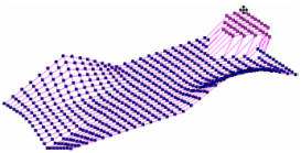
3D Mesh Properties
Enables you to change properties of the 3D mesh.

Table of vertices: Displays the 3D Mesh Coordinates dialog, in which you can adjust the coordinates of each node. Use the Row Number spin control to choose the row of the mesh base.
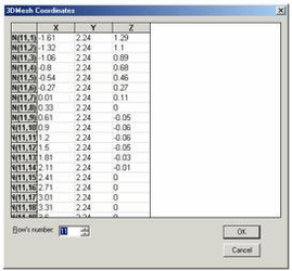
This is different than the coordinates table you used to create the mesh. In this table you can edit coordinates of all points, including interpolation nodes. Smooth: Gives the mesh a smooth appearance in render mode.