Local Surface Utilities

Match Surface
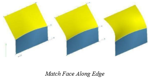
The Match Surface tool modifies the surface continuity at a given edge to a referenced edge. The surface that is to be modified must not be a trimmed surface.
Using the Match Surface tool
Select the surface edge that will be modified in the match operation.
Select the surface edge that will be matched to.
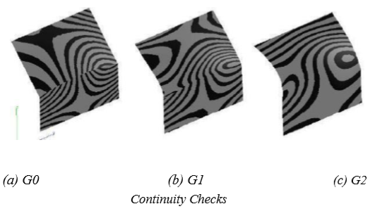
The Verify:Surface Analysis:Zebra plot is very useful in combination with the Match Surface tool. The Zebra Plot helps visualize continuity between two surfaces. G0 continuity will show positional discontinuity in the strips. G1 shows positional continuity but strips do not transition smoothly. G2 show positional and smooth transitions between strips.
Rebuild Surface
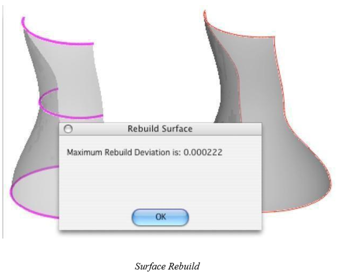
The Rebuild Surface tool reconstructs an approximating surface to the referenced surface. The tightest tolerance achieved is displayed in a dialog box. If the tolerance achieved is not tight enough, use Undo to put the surface back in its original condition.
The Rebuild Surface tool is useful for converting analytics to NURBS, trimmed surfaces to untrimmed surfaces, and repairing surfaces. The rebuild tool is limited to surfaces with 3 or 4 sides.
Rebuild uses refitting algorithms to recalculate a new NURBS surface from the original. The rebuild will perform the following:
Turns the resultant surface into a cubic surface.
May reduce the number of control points.
Fits an untrimmed surface to a trimmed surface.
Repairs bad or questionable underlying geometry.
Removes any discontinuities with the surface.
Using the Rebuild Surface tool
Select the surface to rebuild.
There are no options or Data Entry Fields for this operation.
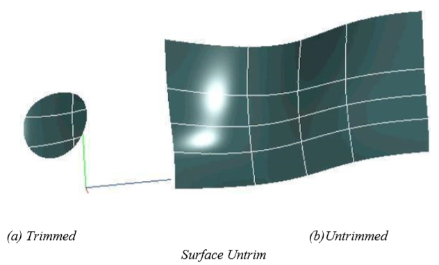
Untrim Surface
The Untrim Surface tool will remove all bounding curves on a surface.
Using the Untrim Surface tool
Select the surface to untrim.
There are no options or Data Entry Fields for this operation.
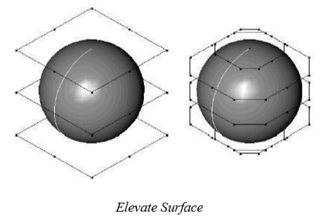
Elevate Surface
The Elevate Surface tool manipulates the underlying mathematical formula of a NURBS surface. NURBS are piecewise polynomial equations of different degrees. Typically surfaces created from skins, covers, and nets are third degree. Some shapes created from cylinders and spheres are second degree. By increasing the degree of a surface, more control points are introduced to aid local modifications. Normally, elevating to degree 5 or 7 provides enough control points to manipulate a surface, although SharkCAD supports up to degree 22.
Using the Elevate Surface tool
Select the surface to elevate.
There are no options or Data Entry Fields for this operation.
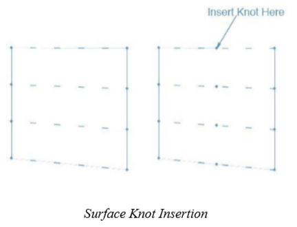
Insert Knot
The Insertion Knot tool introduces a new row or column of control points to a surface. By inserting a knot into a surface, you gain more control points to manipulate for finer control over a shape. To use the Insertion Knot tool, pick a boundary edge on which to insert the knot.
Using the Insert Knot tool
Select the surface to insert a knot.
There are no options or Data Entry Fields for this operation.
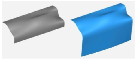
Surface Extend
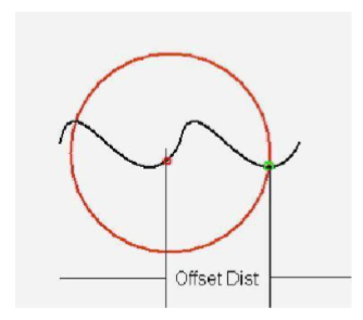
The Surface Extend tool will lengthen a side of the surface along its curvature. Selecting a face extends all of the edges associated with that surface. All of the underlying associativity is preserved and the offset distance by which the surface is extended can be defined on the Prompt window.
Using the Surface Extend tool
Click a surface or edge to extend it the amount specified by the Offset field.
The resulting surface is offset in a manner that the 3D distance between the two is the specified offset distance; the distance is not measured along the actual surface (distance along the arc).
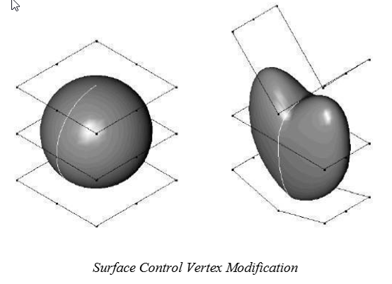
Surface Control Vertex Modification
SharkCAD supports the manipulation of control points for a NURBS surface. This function is limited to “Surface Face” surfaces. For example, if you have a net, skin or cover surface, first change the object type by removing the associative links. Then use the Show Points tool to display the surface control points. In the example below, a solid sphere was converted to a Surface Face. Next, Show Points was used to expose the surface control points. The control points were than translated and moved to new positions to reshape the sphere into a heart shape. It is now possible to create a crease in the surface with this tool. Be sure to use surface analysis tools in conjunction with control vertex modification if surface smoothness and continuity are an issue.