Local Face Operations

Face operations tools allow you to manipulate individual object faces. These operations include:
Push/pull (extrusions and protrusions)
Draft
Match
Move
Offset
Remove
Replace
Parting Line
Deform (SharkCAD Pro Only)
Patterns (SharkCAD Pro Only)
Push/Pull
The Push/Pull tool allows you to create 3D objects from 2D lines or curves by simply dragging to extrude an enclosed shape. This tool can also be used to resize 3D objects by dragging a face.
The Push/Pull tool detects lines or curves that exist on a face, so you can use the Push/Pull tool to extrude individual faces that are made up of enclosed lines and curves to create protrusions and holes within an object.

As you’re dragging, if the face you are pushing/pulling becomes co-planar with another existing face, the existing face appears highlighted so you know when the two faces are aligned. This makes pushing or pulling faces into alignment with existing faces very easy.
Using the Push/Pull tool
Position your cursor over an enclosed 2D profile or face. The text “face on” appears when you’re on an acceptable surface. Hold down your left mouse button and drag in the direction you want to push/pull. Release when the face is at the desired distance. (optional) Enter values in
the Data Entry window to specify the distance.
Using the Push/Pull tool to extrude individual faces on an object
Draw a line, curve, or polygon to create an enclosed face within a larger object.
Click the Push/Pull tool.
Hold down your left mouse button and drag the face in the direction you want to push/pull.
Release when the face is at the desired distance. (optional) Enter values in the Data Entry window to specify the distance.
Draft
The Draft Face operation will rotate a collection of faces about an edge. The Draft Face tool will extend or relimit adjacent faces. The following terms are used when creating a drafted face.
Reference Face A face whose normal defines the draft angle. Sometimes this is referred to as the pull direction for molds.
Reference Edge A linear edge whose direction defines the draft angle.
Neutral Position A face whose normal defines the pull direction. Since this position doesn't change, it is called the neutral position.
Using the Draft tool
Select the reference face for the draft angle.
Select the faces to draft.
Use Shift key for multiple faces.
Specify the neutral point.
Use the Data Entry Fields to change the draft angle.

Match Face
The Match Face command will modify the orientation and position of a selected face to that of a referenced face.
Using the Match Face tool (To Face)
Select face to modify.
Select the face to match.
There are no Data Entry Fields entries for this command.
Using the Match Face tool (To Surface)
Select face to modify.
Select the surface to match.
There are no Data Entry Fields entries for this command.

Move Face
The Move Face tool will translate one or more faces by a vector amount. Neighboring faces are extended or relimited to account for the new position.
Using the Move Face tool
Select one or more faces to move.
Specify two points for the move direction and magnitude.
Use the Data Entry Fields to adjust the dx, dy, and dz components.
Offset Face
The Offset Face tool will offset one or more faces a positive or negative distance. Neighboring faces are relimited to the new offset face.
Using the Offset tool
Use the Data Entry Fields to specify an offset value.
Select one or more faces to offset. In the figure below, top face in red is offset upwards.
Remove Face
The Remove Face tool will delete one or more faces from a part. More than one face can be removed in one operation. Internally, neighboring faces are extended and relimited to account for the removed faces.
Using the Remove Face tool
Select faces to remove.
Hold the Shift key for multiple faces as in example below.
There are no Data Entry Fields entries for this tool.
Replace Face
The Replace Face tool will substitute a new surface for the selected face. The surface must lie precisely along the edges of the face to replace.
Using the Replace tool
Select the face to replace.
Select the surface to replace with.
The example below shows the surface translated up for clarity.
The surface must lie on the face edges that are being replaced.
Parting Line
The Parting Line tool will take a collection of curves that lie on a solid, imprint them onto the solid (creates split faces), and add draft to the upper and lower surfaces relative to the parting line.
Using the Parting Line tool
Select the part for the parting line operation.
Use the Data Entry fields to specify upper and lower draft.
Select the curves that lie on the solid for the parting line.
Deform Face (SharkCAD Pro Only)
The Deform Face tool is used to inflate or deflate a face to an optional point or curve constraint. The deform tool has three creation methods.
Pressure Gain Inflates or deflates based on a pressure gain. Useful for doming faces.
To Point To Inflates or deflates a face to a point.
Curve Inflates or deflates to a curve.
Using the Deform tool (Gain)
Select the first icon which deforms to a pressure gain. Select the face to deform.
Use the Data Entry Fields to adjust the gain. Negative gains (as in example below) will move the surface in a direction opposite of its surface normals.
Iso lines are displayed in the figure to the right to better visualize the deform.
Using the Deform tool (To Point)
Select the second icon which deforms to a point.
Select the face to deform.
Specify two points that define a from to vector. (A point entity is created that you can later modify.)
Use the Data Entry Fields to adjust the surface gain.
Using the Deform tool (To Curve)
Select the third icon which deforms to a curve.
Select the face to deform.
Select the curve to deform to.
The curve must project completely onto the face to deform.
Deform Options
The Deform feature has a variety of options for controlling how the face is deformed. These are accessed through the Inspector.

Gain
The Gain value is similar to a constraint pressure applied to the surface. Use positive gain to inflate the surface and negative to deflate. Depending on the stiffness and resolution of the surface, practical gains can range anywhere from 0 to 1000000.
Stretch Factor
The Stretch Factor controls the deformable surface’s resistance to stretching.
A surface with a large stretch value is said to be stiff. Deformable surfaces with large stretch values act like soap bubbles seeking to always minimize their area. This results in flatter looking surfaces that allow regions of rapid bending.
Bend Factor
The Bend Factor controls the deformable surface’s resistance to bending. Deformable models with large bend values act like elastic beams attempting to distribute regions of bending over large areas and typically generate very fair shapes.
Resolution
The Resolution Slider controls the precision of the resultant deformed shape by inserting additional control points to the surface. Higher resolution values will show more detail for the given deformation values. Lower resolution values calculate faster but with less detail. When using the tangent and curvature options, start with a resolution factor of 80 for best results.
The following options apply only to pressure deformations, the first tool icon. It does not apply to deformations to a point or curve. Be sure to use higher resolutions when using the below options to insure tangency and curvature precision with the results.
No Tangency
The No Tangency option deforms the face and allows the shape at the edges to deform.
Local Face Tangent
The Local Face Tangent option deforms the shape but preserves the existing tangencies of the face.
Shared Faces Tangent
Shared Faces Tangent will modify all faces that share edges with the face being modified. The modification will impose tangencies at all
shared edges.
Shared Faces Curvature
The Shared Faces Curvature option will modify all faces that share edges with the face being modified. The modification will impose curvature continuity at all shared edges.
Shared Faces Tangent Fixed
The Shared Faces Tangent Fixed option will only modify the selected face to be tangent to all faces that share an edge with the selected face.
Shared Faces Curvature Fixed
The Shared Faces Curvature Fixed option will only modify the selected face to be curvature continuous to all faces that share an edge with the selected face.

Pattern (SharkCAD Pro Only)
Solid modeling often involves the repetition of features or objects arranged in a regular or irregular manner (copied or transformed), which may be referred to as patterns. Examples of patterns include the radial arrangement of holes in a showerhead, the linear grating of ventilation holes on a computer monitor or the treads on a tire. Creating such patterns can become unnecessarily burdensome, especially when the number of repetitive elements grows large.
The Pattern tool reduces this burden by offering pattern types to facilitate pattern creation. The following eight patterns are available on the Data Entry window, once the tool is activated:

Linear
Creates a linear pattern specified by quantities along the x, y, and z-axis. Spacing is controlled by the dX, dY, and dZ filed on the Data Entry window. Use the Hex option to stagger the rows to create a hexagon pattern.
Polar
Creates a polar array pattern specified by the number of angles.

Polar Grid
Creates a polar grid pattern specified by the number of angles.

Radial
Creates a radial pattern specified by the number of angles.

Cylindrical
Creates a cylindrical pattern specified by the number of angles.

Spherical
Creates a spherical pattern specified by the number of angles.

Along Path
Creates a pattern along a curve path.

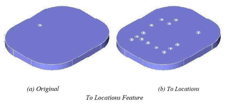
Copy to Locations
Creates a pattern by specifying locations.