Feature Based Solids
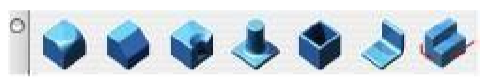
A feature is a set of operations that simplify the building or modification of a solid by a common design task. Features include Booleans (add, subtract, intersect), fillets, chamfers, countersink, counterbore, boss, cutouts, protrusions, and splitting.
Fillet/Blend
The Blend tool creates a constant radius fillet or rounds the edge of a solid. A fillet is a blend operation that adds material, whereas a round subtracts material. SharkCAD divides its blending functions through two icons that represent tools for constant and variable cross section blending.
Constant Cross Section Variable Cross Section Radial Linear Elliptical By Position Vertex Blend Radius Curve Fixed Width Hold Line Three Face Blend Curvature Continuous
Constant Blend
The Constant Blend tool creates a constant radius fillet across one or more edges. There are three types of constant blends available on Data Entry window.
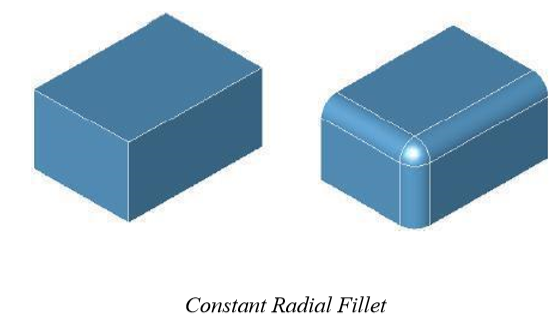
Using the Constant Radial Fillet tool
Select the solid edge or face you want to fillet. Hold down the Shift key if you need to fillet more than one edge.
Use the Data Entry Fields to adjust the radius value.
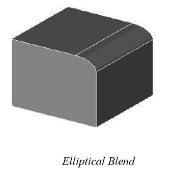
Elliptical Fillet
The Elliptical Blend option defines an elliptical cross section for the blend. The ellipse ratio is the relationship between the major and minor radii of an ellipse. The major radius is defined in the Data Entry Fields and edit box. The minor radius is the product of the major radius and its ratio.
Using the Constant Elliptical Fillet tool
Select the Constant Blend tool from the Blend Edge sub-•tools palette.
On the Data Entry window, click the drop-•down and choose Elliptical.
Select the edge you want to fillet. Hold the Shift key down if you need to fillet more than one edge.
Use the Data Entry Fields to adjust the radius value.
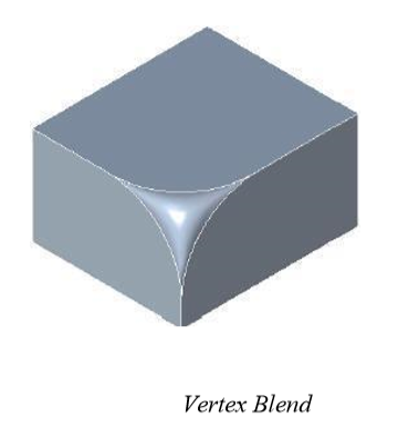
Vertex Blend
A Vertex Blend places a blend at the corner, where three or more edges meet. The vertex blend is limited to corners that share the same convexity.
Using the Vertex Blend tool
Select the Constant Blend tool from the Blend Edge sub-•tools palette.
On the Data Entry window, click the drop-•down and choose Vertex Blend.
Select the vertex you want to fillet.
Use the Data Entry fields to adjust the radius value.
Variable Linear Blend
The Variable Blend tool creates a fillet that has a starting radius value that is different from the ending radius value. There are seven types of variable blends available on the Data Entry window.
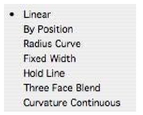
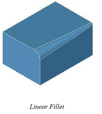
Linear
The Linear option fillets an edge along a selected line. The R1 and R2 values specify the radius.
Using the Linear Fillet tool
Select the Variable Blend tool from the Blend Edge sub-•tools palette.
Select the edge you want to fillet. Hold down the Shift key to select multiple edges. Use the Data Entry Fields to adjust the start and end radius value.
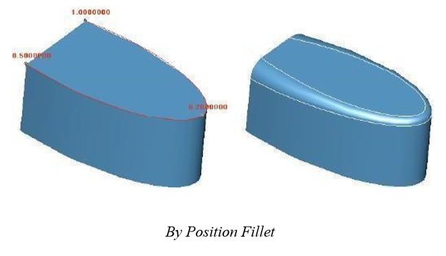
By Position
The By Position Fillet tool allows you to specify radius values at specific locations along the edge to blend.
Using the By Position Fillet tool
Select the Variable Blend tool from the Blend Edge sub-•tools palette.
On the Data Entry window, click the drop-•down and choose By Position.
Select the edge you want to fillet. Hold the Shift key down to select multiple edges.
Click at a location on the edge and specify the associated radius value.
Terminate with a right click, double click or hit Enter from the keyboard.
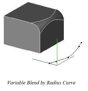
Radius Curve
The Radius Curve option allows you to select an edge to blend and a curve to define the radius distribution. The curve must be in the positive xy quadrant with the y value representing the radius. The percent along the curve is mapped to a percent along the edge being blended. One of the advantages of controlling the radius by a curve is that you can add or remove control points and set the slope.
Using the Radius Curve tool
Select the Variable Blend tool from the Blend Edge sub-•tools palette.
On the Data Entry window, click the drop-•down and choose Radius Curve.
Select the edge you want to fillet.
Select radius curve for the fillet.
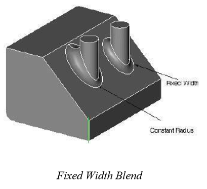
Fixed Width
The new Fixed Width function, located in the variable cross section pull-down, sets the explicit width between the tangent lines. In this case the radius value fluctuates for a constant width blend.
Using the Fixed Width tool
Select the Variable Blend tool from the Blend Edge sub-•tools palette.
On the Data Entry window, click the drop-•down and choose Fixed Width.
Select the edge you want to fillet.
Use the Data Entry Fields to specify a fixed width radius value.
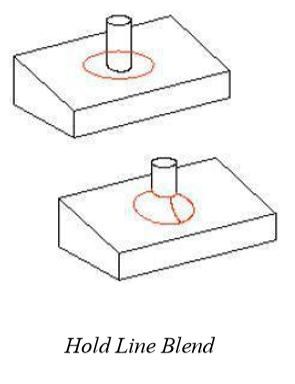
Hold Line
The Hold Line blend specifies one of the tangent lines of the resulting blend. A variable radius blend is created to match the hold line.
Using the Hold Line tool
Select the Variable Blend tool from the Blend Edge sub-•tools palette.
On the Data Entry window, click the drop-•down and choose Hold Line.
Select the edge you want to fillet.
Select curve for the fillet hold line.
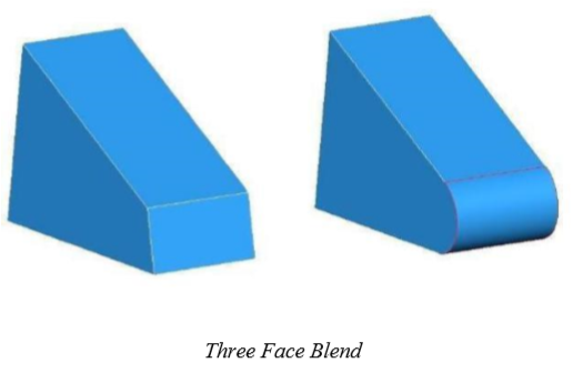
Three Face Blends (SharkCAD Pro Only)
The Three Face Blend tool creates a variable radius blend between three faces. The center or shared face is replaced with a smoothly blended surface. The radius is controlled completely by the geometry of the three faces.
Using the Three Face Blend tool
Select the Variable Blend tool from the Blend Edge sub-•tools palette.
On the Data Entry window, click the drop-•down and choose Three Face Blend.
Click the first side of the blend.
Click the second side of the blend.
Click the center of the blend.
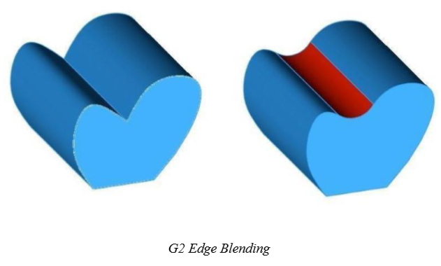
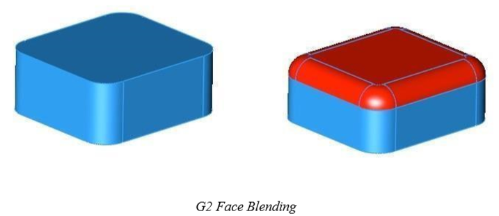
Curvature Continuous
The Curvature Continuous blend tool creates a G2 fillet surface along selected edges. A G2 blend takes into consideration the second derivative of the adjacent faces, creating a blended surface where the radius of curvature is continuous across the shared boundary.
Using the Curvature Continuous blend tool
Select the Variable Blend tool from the Blend Edge sub-•tools palette. On the Data Entry window, click the drop-•down and choose Curvature Continuous. Specify the radius in the Data Entry Window Select the edges to blend.
This tool also allows you to pick a face for blending. When a face is selected, all of its edges are assigned a variable radius.
Important: There is no automatic blend reordering, as with constant radius blending. It is recommended that larger radius edges be blended first. Also, chained edges must use the Tangent Continuous method;; non-•tangent edges will be ignored.
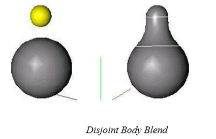
Face/Face Blends
The Constant Radius Fillet tool allows the selection of face/face blends instead of the normal edgebased blending. Face/face blending allows you to perform disjoint blends where the faces do not share a common edge.
Creating Face/Face Blends
Pick the Constant Radius Fillet tool.
Use the Data Entry Fields to specify a suitable radius value.
Hold the Shift key, and select the first face.
While still holding the Shift key, select the second face.
Click a point between the two faces for a helper point.
Blend Options
The Blend tools have advanced options that are available. Click the Options button to display the Advanced Blend Options dialog.
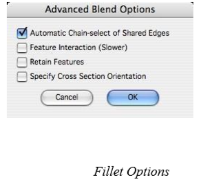
Automatic Chain-Select of Shared Edges
When you select an edge, all edges that are tangent continuous are automatically selected as well.
Feature Interaction
The Feature Interaction option will recognize and preserve additional intersections such as protrusions and cutouts within the blend region. This requires a longer blending time.
Retain Features
The blending has an option to preserve cutouts or protrusions.
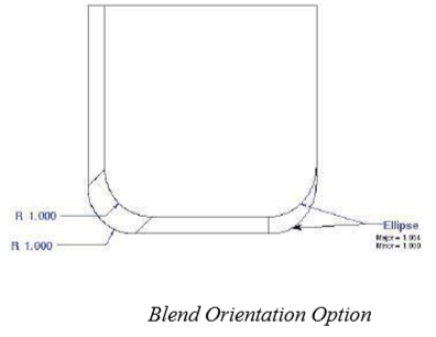
Specify Cross Section Orientation
Normally the blend cross section is perpendicular to the edge being blended. Using this option, select a curve representing the spine that defines the cross section orientation. For example, in the figure below, the blend on the right was created by the defaults. The one on the left side represents the blend created by picking a vertical edge for the cross section orientation.
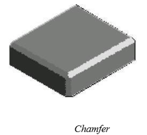
Chamfer
A Chamfer feature adds or removes a flat section of material from a solid along a collection of one or more selected edges. The flat section creates a beveled surface between the surfaces common to the selected edges.
SharkCAD supports nine user interface options for creating chamfers. These nine options are classified into constant cross-section and variable cross-section chamfers. Constant chamfers maintain the cross section properties from start to finish, whereas variable cross sections change lengths by a variety of options.
Constant Cross Section Variable Cross Section
Length Lengths Two Lengths Four Lengths Length/Angle Length/Angles Vertex Corner By Position
Fixed Width
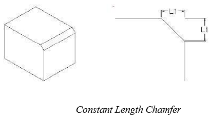
Length
This tool creates a constant length chamfer across one or more selected edges. The length from the common vertex is the same.
Creating Length Chamfers
Use the Data Entry Fields to specify a suitable chamfer value.
Select the edges for chamfering.
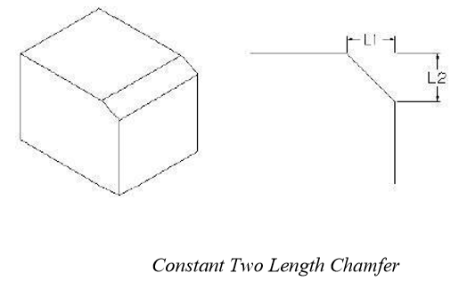
Two Length
This tool creates a constant two length chamfer across one or more selected edges. Two lengths are used to specify the distance from the common vertex.
Creating Two Length Chamfers
Use the Data Entry Fields to specify chamfer length 1 and length 2 values.
Select the edges for chamfering.
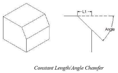
Length/Angle
This tool creates a constant length/angle chamfer across one or more selected edges. A length offset is used to measure the distance for side one and angle for the other.
Creating Length/Angle Chamfers
Use the Data Entry Fields to specify a suitable chamfer length and angle values. Select the edges for chamfering.
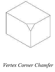
Vertex Corner
The Vertex Corner Chamfer creates a notch at the corner of a solid, where three or more edges meet. The setback is the distance from the vertex back along the shared edges to the vertex. Vertex Corner requires the surfaces be planar.
Creating Vertex Corner Chamfers
Use the Data Entry Fields to specify a suitable chamfer distance.
Select the vertex for chamfering.
Variable Chamfer
This tool creates a variable lengths chamfer across one or more selected edges.
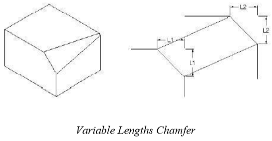
Lengths
The Lengths option chamfers an edge along a selected line. This uses two length offsets where the lengths are applied to the start and end of the chamfer.
Creating Variable Lengths Chamfers Use the Data Entry Fields to specify the two lengths. Select the edges for chamfering.
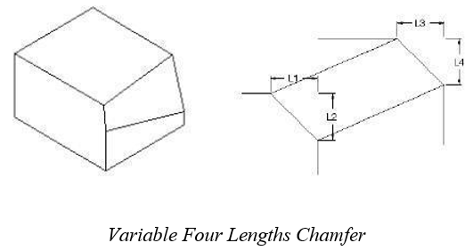
Four Lengths Chamfer
This tool creates a variable lengths chamfer across one or more selected edges. This uses four length offsets where two lengths are applied to the start and two at the end of the chamfer. Length 1 and 2 are applied to the start of the edge.
Creating Four Length Chamfers
Use the Data Entry Fields to specify the four lengths.
Select the edges for chamfering.
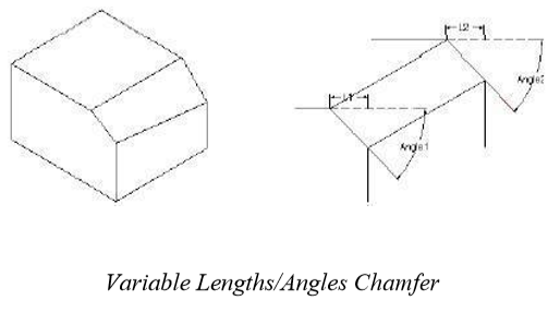
Lengths/Angles Chamfer
This tool creates a variable lengths chamfer across one or more selected edges. This uses a length/angle setting at the start and another at the end.
Creating Lengths/Angles Chamfers
Use the Data Entry Fields to specify the length/angle pairs. Select the edges for chamfering.
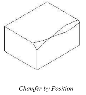
By Position Chamfer
The Chamfer by Position tool specifies set-back values at locations along an edge. This tool’s user interface is similar to the Variable Radius by Position tool.
Creating By Position Chamfers
Select the edges for chamfering.
Click a position along the edge and type in a chamfer length in the Data Entry Window.
Continue defining positions, end with ESC, ENTER, right click or double click.
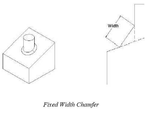
Fixed Width Chamfer
The Fixed Width Chamfer creates a chamfer that controls the distance between the chamfer edge lines, similar to controlling the hypotenuse of a triangle. The distances vary to maintain the fixed width value.
Creating Fixed Width Chamfers
Use the Data Entry Fields to specify a fixed width value.
Select the edges for chamfering.
Chamfer Options
The chamfer options have attributes for chaining neighboring tangent edges, facilitating feature interaction, and retaining features.
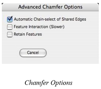
Automatic Chain-Select of Shared Edges
When you select an edge, all edges that are tangent continuous are automatically selected as well.
Feature Interaction
The Feature Interaction option will recognize and preserve additional intersections such as protrusions and cutouts within the chamfer region. This requires a longer chamfering time.
Retain Features
The blending has an option to preserve cutouts or protrusions.
Hole
Holes are very useful for modeling bolt holes found frequently in mechanical design parts. In SharkCAD holes are a predefined feature that removes cylinder shapes from an object. Holes, like other features in Punch! Shark, are associative and can be modified at any point in the design process. SharkCAD supports three hole types:
Simple
Counterbore
Countersink
All three hole creation tools will prompt the user to project the snap point if the snap point does not lie on the face. The snap is projected along the hole orientation to the selected face.
Hole Depth
The Prompt window contains a drop-down menu with options that control the depth of the hole. The options include:
To Depth The hole depth is defined by a user defined distance.
Through The hole goes completely through the body.
First Blind The hole stops at the first outward face it intersects.
To Face The hole terminates at a user defined face.
Hole Orientation
The Prompt window contains a drop-down menu with options that control the orientation of the hole. The options include:
Normal
X-Axis The hole is perpendicular to the face normal.
Y-Axis The hole axis is aligned with the global x axis.
Z-Axis The hole axis is aligned with the global z axis.
2- Pts The hole axis is aligned with user supplied two points.
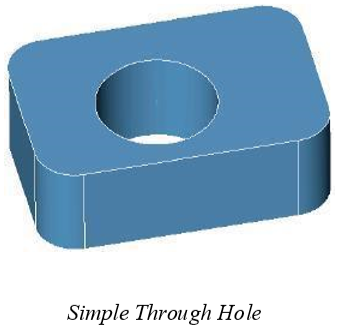
Simple Hole
A Simple Hole is defined by a hole center point, radius, and depth.
Creating a Simple Hole
Select the hole depth of “Through”. Select the hole orientation of “Normal”. Pick the face for the hole.
Specify location for hole center.
Adjust the hole center, diameter, and draft angles using the Data Entry Window.
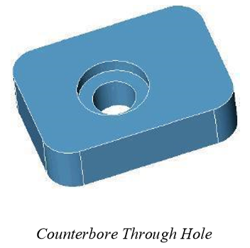
Counterbore Hole
A Counterbore feature allows the designer to specify a bore depth and bore radius in addition to the main radius and depth. The bore radius should be greater than the hole radius and the bore depth must be less than the hole depth. Unlike the countersink which has angled sides, the counterbore has straight sides.
Creating a Counterbore
Hole Select the hole depth of “Through”.
Select the hole orientation of “Normal”.
Pick the face for the hole. S
pecify location for hole center.
Adjust the hole center, diameter, bore depth, bore diameter, and draft angles using the Data Entry Window.
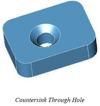
Countersink Hole
A Countersink feature allows the designer to specify a sink angle and sink diameter in addition to the main radius and depth. Unlike the counterbore which has straight sides, the countersink has angled sides.
Creating a Countersink Hole
Select the hole depth of “Through”.
Select the hole orientation of “Normal”.
Pick the face for the hole. Specify location for hole center.
Adjust the hole center, diameter, sink angle, sink diameter, and draft angles using the Data Entry Window.
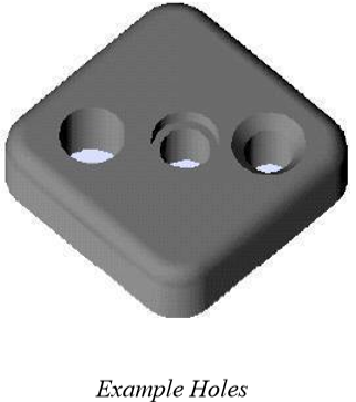
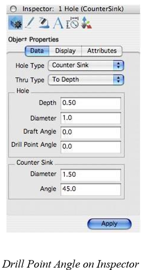
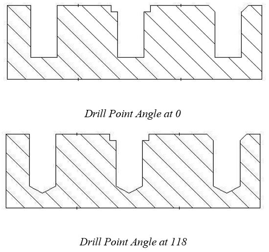
Drill Point Angle
The drill point is an attribute of holes; you can specify a drill point angle. When a hole is selected, the Drill Point Angle field is available on the Inspector. You can enter a value to create a drill point angle.
Below is an example of a simple hole, counterbore, countersink, (left to right):
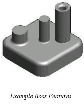
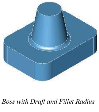
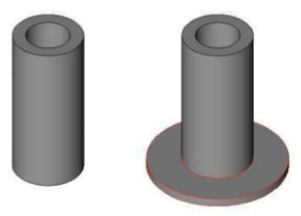
Boss
A Boss is a cylinder added to another solid with a radius applied at the intersection of the cylinder and base. You can also add draft to the cylinder.
Boss Orientation
The Boss message line contains a pull-down menu with options that control the orientation of the boss. The options include:
Normal The boss is perpendicular to the face normal.
X-Axis The boss axis is aligned with the global x axis.
Y-Axis The boss axis is aligned with the global y axis.
Z-Axis The boss axis is aligned with the global z axis.
2- Pts The boss axis is aligned with user supplied two points.
Creating a boss feature
Select the boss orientation of “Normal”.
Pick the face for the boss.
Specify location for boss center.
Adjust the boss height, diameter, radius, and draft angles using the Data Entry Window.
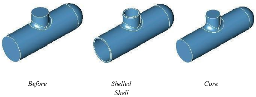
Shell
The Shell tool creates a parametric feature that is frequently used for cast and molded parts. Material from the part interior is removed leaving a hollow cavity. The Shell tool allows you to select faces to leave open; if no faces are selected, the part is hollowed inside. Use the Option key to keep the material removed (Keep Core).
Using the Shell tool
Select the part to shell.
Hold the Shift key and select open faces (click outside the part to hollow entire part).
Adjust the shell thickness using the Data Entry Window.
Use the Inspector to set thickness values to individual faces.
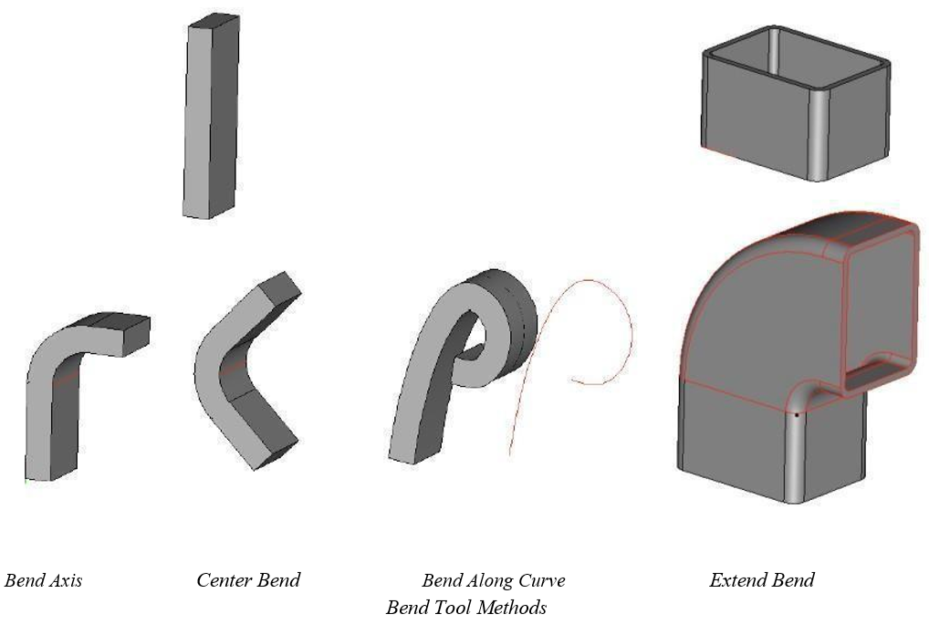
Bend
The Bend tool will bend a solid about an axis. There are two Bend tool options in the Message Line:
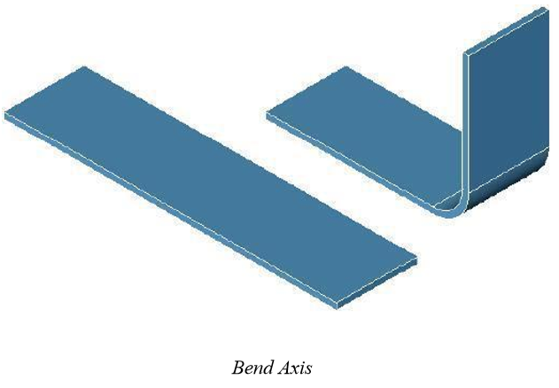
Bend Axis
Bends a solid using the axis as the initial bend plane.
Center Bend
Bends a solid using a center bend.
Bend Along Curve
Bends a solid along a curve.
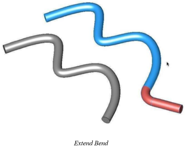
Extend Bend
Lengthens a solid by the specified amount and introduces a bend at given angle and radius.
Using the Bend Tool
Pick the bend option you want.
Select the part to bend.
Specify two points for the bend axis.
Adjust the bend radius and angle using the Data Entry Window.
Using the Bend Tool
Pick the extend bend solid icon (last icon in the sub-•toolset). Select the face to extend. Click an edge to specify to direction in which you want the extension.
Adjust the bend radius and angle using the Data Entry Window.
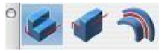
Edge Treatments (Shark CAD Pro Only)
Edge treatments add or remove material based on user-supplied parameters and are associated with the edge of a part. There are three edge treatments supported:
Lip
Groove
Flange
The parameters or properties, of the resulting geometry are controlled on the Prompt window.
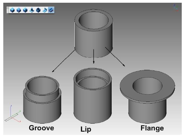
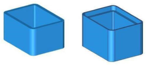
Groove
The Groove tool removes material below the selected face on the selected edge using the supplied height, width, and angle.
Using the Groove tool
Select the face for the groove.
Click an edge for the removed groove.
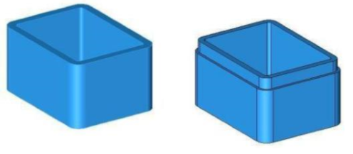
Lip
The Lip tool adds material above the selected face, on the selected edge, using the height, width, and angle values.
Using the Lip tool
Select the face where you want the lip to appear.
Click the edge you want to remain.
The other edge is repositioned to create the lip.
Flange
The flange tool creates a support structure on a given part. Parameters for a flange are offset and thickness.
Using the Flange tool
Select the face for the flange.
Click an edge in the direction for the flange.
Feature Editing
One of the more powerful features of SharkCAD is the transparent parent/child associativity for solid objects. As you create and add features to your part, SharkCAD automatically establishes relationships between the parts. When you modify or change a parent the children all get regenerated. For example, consider the following history of a part:
Create a block primitive. Fillet the edges of the block.
Create a boss at the block center.
Create a countersink hole at the boss top center.
Now try these modifications on the part:
Select any face or edge associated with the original block from step 1. Object Info the block parameters and change the length, width, and height. Note all steps 2-•4 automatically regenerate based on the new l, w, and h.
Select any face or edge introduced by the fillet command from step 2. Change the radius value, and note that steps 3 and 4 automatically regenerate.
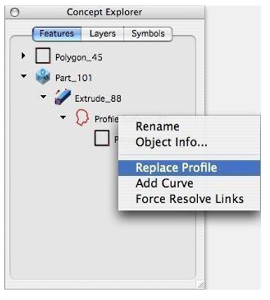
Profile Updates
Feature based solids are created from collections of 2D curves called profiles. The Concept Explorer displays a Profile Surface entity that contains a list of curves defining a closed profile. Right-clicking on the Profile Surface entity displays a menu that provides options to replace the entire profile or add a curve to the existing profile.
Replace Profile
This option prompts you to select a new set of curves that will redefine the profile.
Add Curve
This option prompts you to select a curve in the plan of the profile to add as part of the profile.
Remove/Replace Curve
Selecting a curve that is listed under a profile will display a menu that allows you to remove or replace the curve.