Concept Explorer
Concept Explorer provides a user interface to access commands for the layer manager, feature tree, and a symbol manager for conveniently dragging and dropping symbols and parts onto your drawing. Layers provide a means to organize entities into displayable levels and the feature tree provides a means to examine and modify associativity, history, and dependencies between objects.
Layer Manager Tab
Layers are a powerful tool for organizing related groups of drawing objects. For example, a user may want to separate the dimension information from the rest of the model. This can be accomplished by using layers. Layers are not new to designers; it is a practice that has been going on long before computer aided design systems. Designers took advantage of drawing on transparent plastic sheets to separate related groups of drawing objects. Designers could then mix and organize these sheets for different presentation purposes. When computers came along, this great idea was designed into most CAD systems.
SharkCAD exposes layers through the Layer Manager tab in Concept Explorer. For each new drawing, the Construction, Dimension, and Layer1 layers are created automatically. A maximum of 1200 layers can be created.
A model object can reside in only one layer at a time. Each layer has several attributes that can be used to control the behavior of newly created or assigned objects. These attributes are discussed below. Where appropriate, sub-layers inherit dominant attribute(s) from their parent layer(s). The dominant attributes are: Hidden, Locked, and Color.
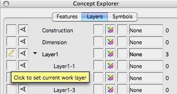
Work Layer
The first vertical column from the left indicates which layer is the current Work Layer. All newly created objects are automatically placed in the Work Layer. The pencil icon (  ) indicates the current Work Layer. Left-clicking on an empty cell or double-clicking on the layer name will change the Work Layer.
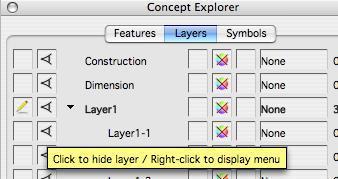
Visible/Hidden
The second vertical column from the left indicates which layers are visible or hidden. If a layer is visible, all objects in that layer are visible in the drawing. If a layer is hidden, all objects in that layer (and sub- layers) are not visible in the drawing. Visible layers display the eye icon ( ). Any sub-layers that are hidden due to a parent override will display the dimmed eye icon (  ). If a layer is hidden, no icon is displayed. Left-clicking on a cell will toggle the visibility of the layer.
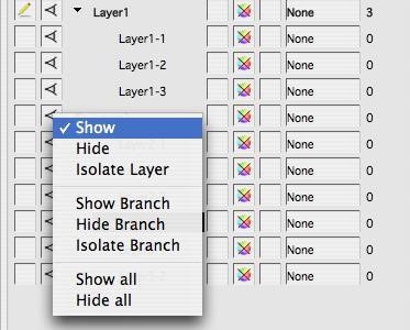
Control-click (right-click) cell to display the visibility pop-up menu. The layer’s current visibility status is indicated by the check mark.
Name
The central area displays the layer tree hierarchy using a series of branches and layer names. If a layer has no sub-layers, the terminal node indicator (  ) is displayed.
If a layer has sub-layers not displayed, the closed node indicator (  ) is displayed. Double-clicking on the closed node indicator will expand this layer and all sub-layers (see Expand Branch menu option below).
If a layer has displayed sub-layers, the open node indicator (  ) is displayed. Double-clicking on the open node indicator will close this layer and all sub-layers (see Collapse Branch menu option below). Left-clicking on a node indicator will toggle the display of sub-layers. Right-click on a node to display the tree menu.
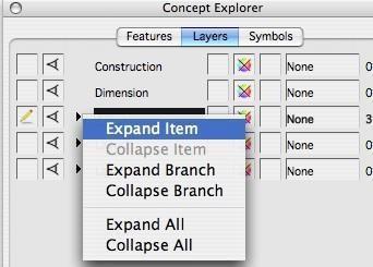
Expand Item Displays the selected layer’s immediate subtree. Pressing the + key is a shortcut for this option.
Collapse Item Closes the selected layer’s immediate subtree. Pressing the - key is a shortcut for this option.
Expand Branch Displays the selected layer’s complete subtree. Pressing the Ctrl+ key is a shortcut for this option.
Collapse Branch Closes the selected layer’s complete subtree. Pressing the Ctrl- key is a shortcut for this option.
Expand All Displays branches for all layers and sub-layers.
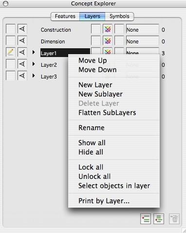
Collapse All Closes branches for all layers and sub-layers. Right-click on a name to display the layer pop-up menu.
Drag to reorder: To drag a layer to a new position, hold down the Shift key and drag the layer to the position you want.
Move Up: Moves the selected layer up one position within its current hierarchy level.
Move Down: Moves the selected layer down one position within its current hierarchy level.
New Layer: Creates a new top-level layer.
New Sublayer: Creates a new layer as a sub-layer under the selected layer.
Delete Layer: Deletes the selected layer and its sub-layers. If any entities exist in this branch, the delete will be confirmed. This option is disabled if the Work Layer is set within this branch.
Flatten Moves entities from existing sublayer(s) to the main layer, removing
the sublayer.
SubLayer
Rename: Activates the in-place edit of the layer’s name. Clicking on the name of the selected layer also activates the in-place edit.
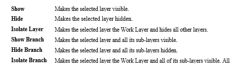
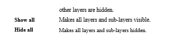
Show all: Makes all layers and sub-layers visible.
Hide all: Makes all layers and sub-layers hidden.
Lock all: Makes all layers and sub-layers locked.
Unlock all: Makes all layers and sub-layers unlocked.
Select Objects in Layer: Selects any object(s) that exist on that particular layer.
Layer Duplicate
A new command to duplicate a layer and all the objects in that layer is now available through Concept Explorer. To access this command, place your cursor over the layer you want to duplicate, right click and select the Duplicate command.
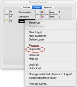
If you Duplicate a sub layer, the new duplicated layer is promoted to a first level layer.
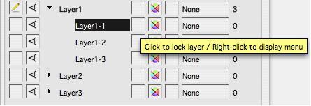
Locked/Unlocked
The vertical column just to the right of the names indicates which layers are locked or unlocked. If a layer is locked, all objects in that layer (and sub-layers) cannot be selected. If a layer is unlocked, all objects in that layer are eligible for selecting. Locked layers display the lock icon (  ). Any sub-layers that are locked due to a parent override will display the dimmed lock icon (
  ). If a layer is unlocked, no icon is displayed. Left-clicking on a cell will toggle the lock on the layer.
Right-click on a cell to display the lock pop-up menu. The layer’s current lock status is indicated by the check mark.
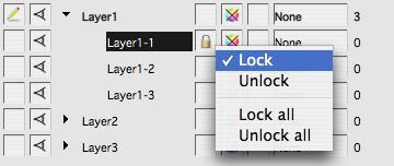
Lock Locks the selected layer.
Unlock: Unlocks the selected layer.
Lock all: Locks all layers and sub-layers.
Unlock all: Unlocks all layers and sub-layers.
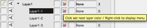
Layer Color
The second vertical column just to the right of the names indicates the layer color. If a layer does not have a color, the no-color icon (  ) is displayed. If a layer has a color, a color sample (
  ) is displayed and all objects in that layer (and sub-layers) will be drawn with the layer color. The layer color takes precedence over the color already assigned to an object. Any sub-layers that are colored due to a parent override will display a multi-color sample (
  ). Left-clicking on a cell will cycle through the standard layer colors (see color menu below).
Right-click on a cell to display the color pop-up menu.
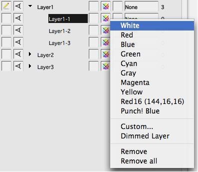
Black – Navy Blue Sets the selected layer’s color a standard color.
Custom… Opens the color chooser dialog to assign a custom color.
Remove: Removes any color from the selected layer.
Remove all: Removes any color from all layers.
Ignore when printed
The column to the right of the Layer Colors allows you to toggle the layer’s visibility when printed.
By default, each layer is printed, but clicking this cell will hide the layer when the design is printed.
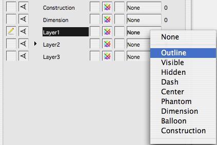
Pen Style Override
The second-to-last column allows you to override the pen style(s) on a particular layer with one uniform style.
Object Count
The number to the right of each layer name indicates object count. If there are no sub-layers or if the sub- layers are displayed, this count represents the number of objects in the layer. The total count and sub- layer count is available using the object count tool tip.
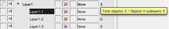
If the layer has undisplayed sub-layers, the count represents the number of objects in the layer and all sub-layers. This total count is differentiated by a + sign to the right of the number. The layer count and sub-layer count is available using the object count tool tip.
The Button Bar
The three buttons at the bottom of the Layer Manager provide easy access to the create layer, create sub- layer, and delete layer operations.

Create a new top-level layer.

Create a sublayer under the selected layer.

Delete the selected layer.
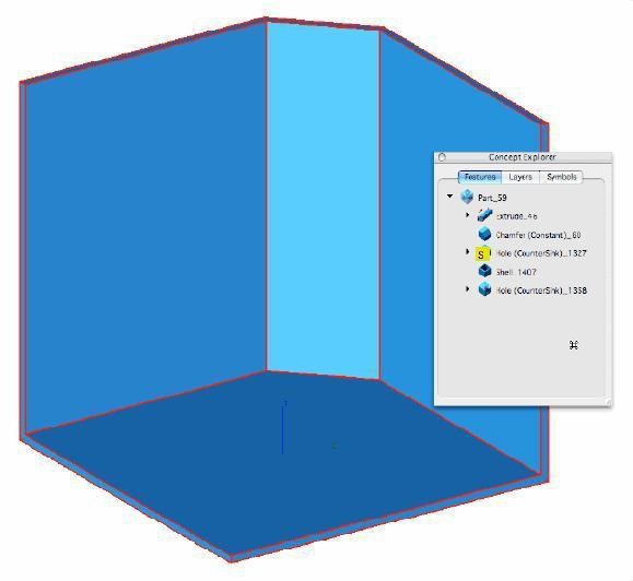
Feature Manager Tab
The Feature Manager Tab displays the associative information related to selected objects. Associative information that can be visually examined and in many cases modified through the feature manager include:
Feature Tree
Curve/Surface Associativity
Feature Tree
The Feature Tree displays the history of the part with respect to the steps used to originally construct the part. Right-clicking on a history node will display a pop-up menu that lets you perform the following operations on a feature:
Feature Suppress
Feature Delete
Feature Reorder
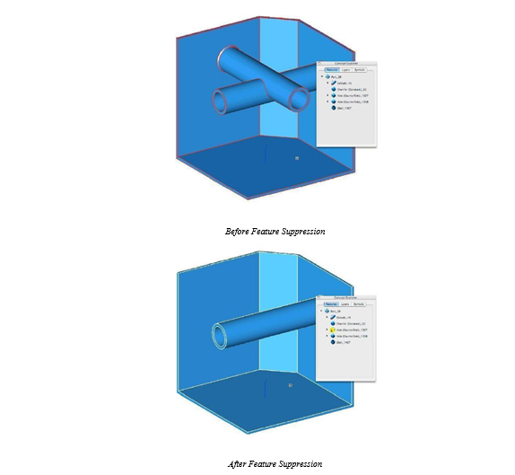
Feature Suppression
Feature Suppression allows you to turn off a particular feature operation in the history tree list of a solid. Suppressed features will rebuild the part as if the suppressed feature operation never occurred. You may unsuppress the feature and return it into the part at a later time.
Feature Delete
Picking this option with remove the selected feature operation.
Feature Reordering
Sometimes you will need to modify your part by rearranging its features. With the reorder command, you can move features up and down the feature tree. Some example uses of feature reordering include:
Curve/Surface Associativity
The feature manager tab does more than just show part history of solids. It also shows you any relationships that may exist with curves and surfaces as well. In addition there are commands to modify or change associative relationships using a pop-up window that appears with a right button click. These tools include commands for adding, removing, and replacing curves used with surfaces or solids.
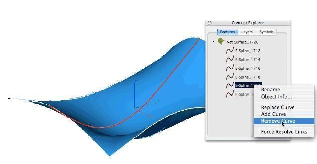
Remove Curve
Remove Curve will delete a curve reference used to define a skin or net surface. The actual curve is not deleted, just removed for the associative links of the surface. You can access the remove curve command using Concept Explorer and right clicking at the curve that you wish to remove.
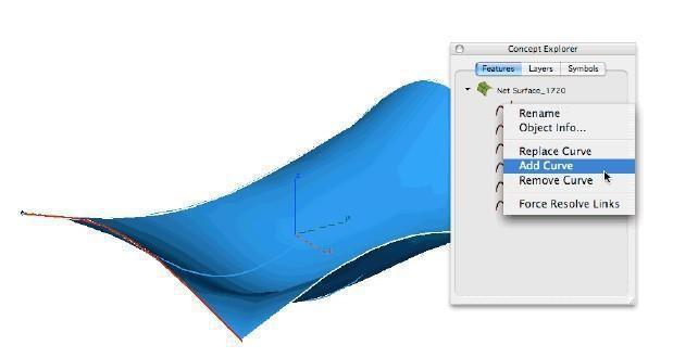
Add Curve
Add Curve will insert a new curve into a skin or net surface. You can access the add curve command using Concept Explorer and right clicking at the curve that you wish to add a new curve after.
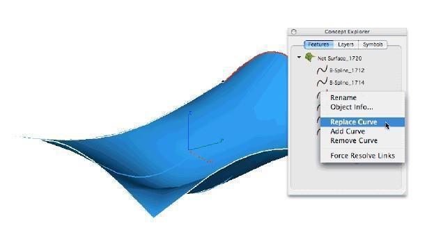
Replace Curve
Replace Curve will substitute a new curve for any curve you see in Concept Explorer. This includes curves for surfaces such as skins and nets as well as curves used to construct profiles for extruded, swept, and lathed solids.
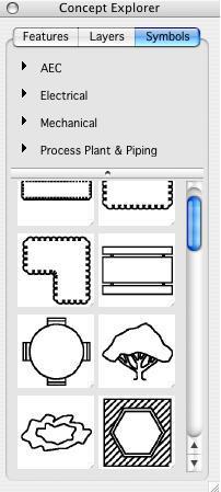
Symbol Manager
The Symbol Manager provides a user interface to drag and drop 2D and 3D symbols and parts into the drawing.
Symbols dragged in from the Symbol Manager display control points that are used to dynamically modify size, angle, and position of the object.
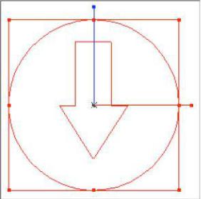
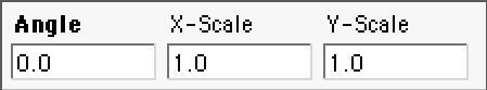
Additionally you can use the data entry fields to precisely modify the scale and rotation angle of the symbol.
Inspector
The Inspector dialog displays a variety of general information regarding the current set of selected object(s), including Object Properties, Pen Properties, Fill Properties, Text Properties, Dimension Properties, and Gripper Properties.
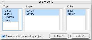
Select Mask
Select Masking provides a method for fine tuning your selections. Selection masks are available by color or object type. See figure below for the Select Mask dialog box.