Edit
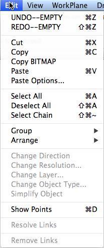
The edit menu contains commands to select and modify objects. Example commands include cut, copy, paste, and select all. Typically, commands in the Edit menu require the entity be preselected.
Undo
This command will undo the last operation. Example commands that are placed in the undo stack include creation, modification, and deletion of entities. Example commands not placed in the undo stack include view operations such as zooming and change views.
SharkCAD supports an unlimited number of undo commands. You can limit the number of undoable commands by checking the Clear Undo List Upon Saves in the File: Preferences dialog box.
Redo
The Redo command will restore the last undo operation. The number of redo operations equals the number of undo operations.
Cut
The Cut command deletes the selected objects and places them in the Clipboard.
The contents placed into the system clipboard are 2D. The internal clipboard for SharkCAD is 3D but does not save associative information.
Copy
The Copy command places a 2D copy of the selected data into the system clipboard, and an unassociative 3D copy into SharkCAD internal clipboard. The Copy command does not alter the selected entities.
Copy BitMap
The Copy Bitmap command provides a means to copy a rectangular region as an image and store in the clipboard as either a bmp or PICT image. This image data can then be pasted into other applications.
Paste
The Paste command will copy the contents of the current clipboard into Punch! Shark. The contents are centered about the last mouse down position.
Paste Options
The Paste Options dialog provides settings regarding how items are pasted into the drawing using the Edit:Paste command. The dialog consists of location and attributes options for pasting content.
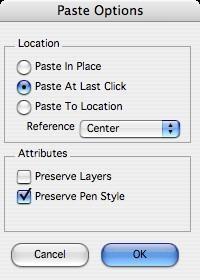
Paste In Place Paste At Last Click Paste To Location Reference
Center
Preserves the original location of the objects in the paste buffer.
Inserts the paste buffer objects at the last click location.
The user specifies a location for the paste buffer objects.
Displays a drop-down defining how the paste buffer objects are aligned to the user location for Paste At Last Click and Paste To Location. Options include:
Upper Left
Lower Left
Upper Right
Lower Right
These references are relative to the current workplane.
Preserve Layers If selected, the Preserve Layers checkbox maintains the original layers of the objects in the paste buffer. If this option is not selected, pasted objects will use the current construction layer.
Preserve Pen Style This option when enabled will keep the original pen styles consisting of color, weight, and pattern. If this is not checked, the pasted objects will use the current pen color, weight, and pattern.
Select All
Use the Edit:Select All command to select all objects in the displayed layers.
DeSelect All
Use the Edit:DeSelect All command to turn off the selection status for all objects.
Select Chain
Selects curve objects that are connected to the currently selected object. To use the Select Chain command:
- Select the start curve as in the figure below.
- Select the Edit:Select Chain command.
- All objects connected to the start or end are selected as in the figure below.
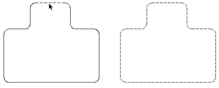
Select start curve Connecting curves selected
Select Chain
Group
The Group command displays a menu with four options. These options are all related to grouping and locking commands.
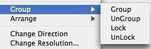
A group is a collection of objects that are treated as one unit. Moving the group will automatically move all members of the group. To create a group, select the objects you want to group, then select the Group option from the Edit:Group menu. SharkCAD supports nested groups.
UnGroup
The Ungroup command will remove the last group entity associated with the selected entities. If the object selected has nested groups, this command only removes the last group operation.
Lock
All SharkCAD objects have a locking attribute flag. The lock attribute prevents all modifications of a locked object. Locked objects cannot be translated, rotated or any other operation that would change the position or shape of an object. However, you can still reference locations from a locked object. To lock an object, use the Edit:Group:Lock command and select the objects to lock.
Unlock
The Unlock command will remove the lock attribute placed on an object. To unlock an object, select the Unlock command from the menu, then select the objects to unlock.
Tip: This is one of the few commands that requires the user select the object after they have selected the command from the Menu Bar.
Arrange
The Arrange command changes the position of the selected objects within the entity list. The entity list is a list of all entities in the file. You can change the position using one of four commands:
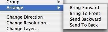
Bring Forward Moves the object one position forward.
Bring To Front Moves the object to the first position in the list.
Send Backward Moves the object one position backward.
Send To Back Moves the object to the last position in the list.
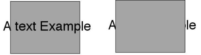
An object’s position in the entity list can impact how the object is displayed with respect to other objects. See figure below where a filled polygon was brought to the front of a text entity.
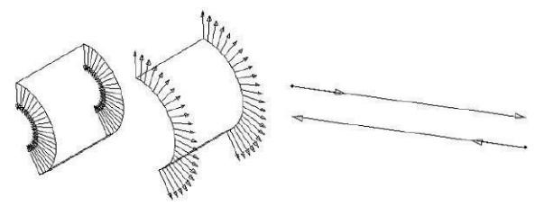
Change Direction
This command will change the orientation of a curve or surface. Changing direction of a curve is sometimes needed when creating certain surfaces such as net surfaces. For surfaces, changing the direction can affect the way the surface is rendered or shaded.
Change Resolution
The change resolution command modifies the display resolution of a curve, surface or solid.
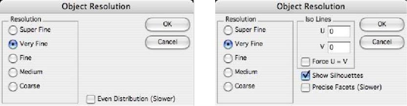
For Curves For Surfaces/Solids
Resolution
In the case of a curve, the Resolution controls the deviation of a line segment to the actual curve. For a surface or solid, the resolution impacts the normal deviation of a planar facet representing the precise definition.
Iso Lines
Iso Lines controls the number of isometric lines calculated across the surface. For example, if you specify 10 x 5 iso lines for a solid, each face on the solid will display a grid of 10x5 curves. Force UV will keep the u and v values the same.
Tip: The grid is applied to an untrimmed surface and then trimmed to the visible portions of the surface. Therefore it is possible you may not see all the Iso Lines you requested.
Show Silhouettes
The show silhouettes checkbox tells the application whether or not to calculate view dependent edges. In the case of NURBS surfaces, this can be a performance drain.
Precise Facets
The Precise Facet checkbox employs an alternate faceting algorithm that takes longer and creates many more facets but can produce more favorable facets for NURBS surfaces with high curvature.
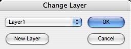
Change Layer
The Change Layer command displays a dialog box to change an entity’s current layer to another layer or a new layer.
Change Object Type
The Change Object Type command provides a means to change the geometry type of selected geometry. Some example operations you can perform with this command include:
| Change From | Change To | |
|---|---|---|
| Curve | Another Curve Type, PolyLines, Lines | |
| Surface | Curves, Mesh | |
| Solid | Curves, Surfaces, Mesh |
Generally when you convert an entity to another entity, any associativity is destroyed.
The exception is when you change a curve to another curve type.
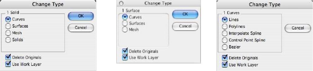
For Solids For Surfaces For Curves
Change Curve
Selecting a curve (line, spline, arc, circle, ellipse or conic) with the Change Object Type will provide the below type conversion options:
Lines Converts the curve’s display list into individual line entities.
PolyLines Converts the curve’s display list into a single polyline with many straight
segments.
Through Spline Refits the selected curve using a fitting algorithm with a through point spline.
Vector Spline Converts the curve into a NURBS, and exposes the control vertices through the
show points command.
Bezier Spline Converts the curve into a NURBS and creates a Bezier spline from the resulting NURBS.
In the example below, a circle is converted into a through point spline, vector spline, and Bezier spline.
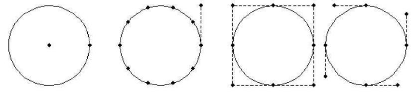
Point Spline
The Convert Curve command is also useful for minimizing over constrained spline curves (splines with too many control points). In the example below, an airfoil with 50 points was reduced to five with the Convert command, while maintaining a tolerance of 0.001 inches.

Minimize Curve
Change Surface
Selecting a surface with the Change Object type will provide the below type conversion options:
Curve Converts the surface exterior edges into individual curve entities. If iso lines are shown, those are converted to curve entities.
Surface Removes associativity with the surface.
Mesh Converts the surface into a facetted mesh object.
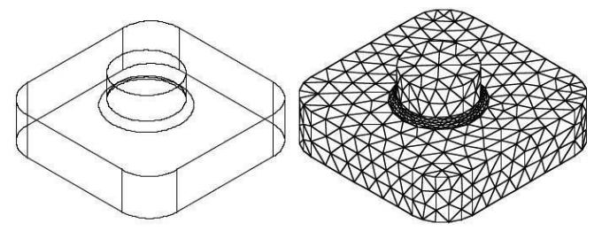
Change Solid
The Change Solid can also be used to convert solids into other entity types. You can convert a solid into a collection of curves, surfaces or facet entity types. Changing a solid to a mesh will display a dialog box with options that control the mesh generation parameters. These options include:
Aspect Ratio Ratio of triangle edges.
Surface Deviation Maximum deviation of surface to facet.
Normal Deviation Maximum deviation between normals.
Maximum Edge Maximum edge length for a facet.
Simplify
The Simplify Object tool will examine the selected objects and, if the entity falls within tolerances, will do the following:
Convert zero length curves to points.
Convert circular splines to arcs or circles. Convert straight splines to lines.
Convert NURBS (Non-Uniform Rational B-Spline) surfaces or solids to analytics.
Potential NURBS shapes converted to analytic shapes include cylinders, cones, spheres, tori, and planes. Candidate shapes for simplification include data imported from IGES, STEP, Rhino, and Alias. In addition, some surfaces created in Punch! Shark, such as skins, are initially created as NURBS and may simplify to an analytic shape.
There are many advantages of analytic representation of shapes over NURBS. Analytic operations are typically considered exact, whereas NURBS are precise. Analytic operations execute much faster internally and take up less memory in RAM and less space when saved to a file. For example, an IGES file was reduced by half after the Simplify tool was executed.
Show Points
The Show Points command will show all editable points on an entity.
Resolve Links
The Resolve Links option examines the current file for any unresolved links and resolves them.
Remove Links
This option takes the selected objects and removes all associativity related to the object.