Mesh Tools
The Mesh Tools menu provides commands for verifying and repairing common issues with meshes such as welding vertices, locating free or manifold edges, repairing holes, and add/delete/combine/split facets.
• Mesh Analysis
• Auto Repair
• Show Free Edges
• Show Non-Manifold Edges
• Remove Collapsed Facets
• Identify Overlaps
• Check Intersections
• Remove Duplicate Facets
• Fix Flipped Normals
• Weld Vertices
• Remove Unused Vertices
• Close Simple Holes
• Rebuild Normals
• Flip One Normal
• Close Seam
• Make Vertices Planar
• HeightMap to Mesh
• Segment Mesh
• Separate All Parts
• Facet From Lines
• Add Facet
• Delete Facets
• Split Facet Edge
• Convert To Quads
• Convert To Triangles
• Reduce Triangles
• Combine
• Split by Select
• Remove silvers
• Coordinate Compare
• Segment Analytic
• Add Crease
• Align Mesh
• Mesh to Analytic
Mesh Analysis
The Mesh Analysis command examines a collection of facets and displays the following information.
• Number of Facets
• Number of Triangles
• Number of Quads
• Surface Area
• Volume (if closed)
• Open Edges
• Collapsed or degenerative faces
• Overlaps
• Double faces
• Number of parts
• Minimum edge length
• Maximum edge length
• Average edge length
• Average aspect ratio
• Highest valence count
Auto Repair
The Auto Repair command inspects and repairs a mesh for the following instances:
• Dangling Vertices
• Stitch Triangles
• Remove Double Faces
• Remove Collapsed Faces
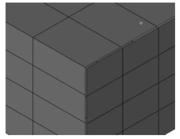
Show Free Edges
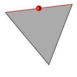
The Show Free Edges command inspects a mesh to see if there are any free edges. If there are free edges, the user is presented with an option to make permanent lines out of the edges illustrated below in red.
Example:
- Select a mesh object.
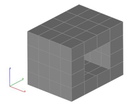
- A dialog box is displayed with the number of free edges found. Free edges are displayed as red lines in the model.
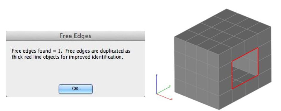
- Press Undo to remove the red lines located at the mesh free edges.
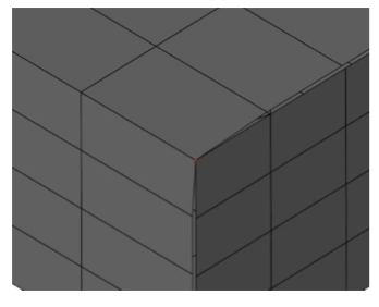
Show Non-Manifold Edges
The Show Non-Manifold Edges examines all edges of a mesh to determine if any one edge has more than two facets sharing the edge. Edges that are determined to be non-manifold displayed with a red line along the edge. Select Undo: Non-Manifold Edges to remove the line from the file.
Remove Collapsed Facets
A collapsed facet contains zero area and can cause issues in other operations. Use the Remove Collapsed Facets command to remove zero area facets from the mesh.
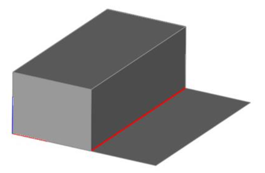
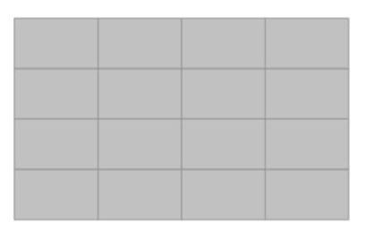
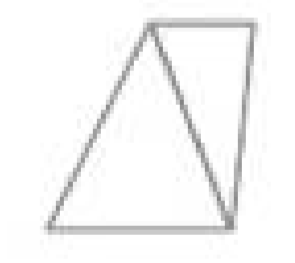
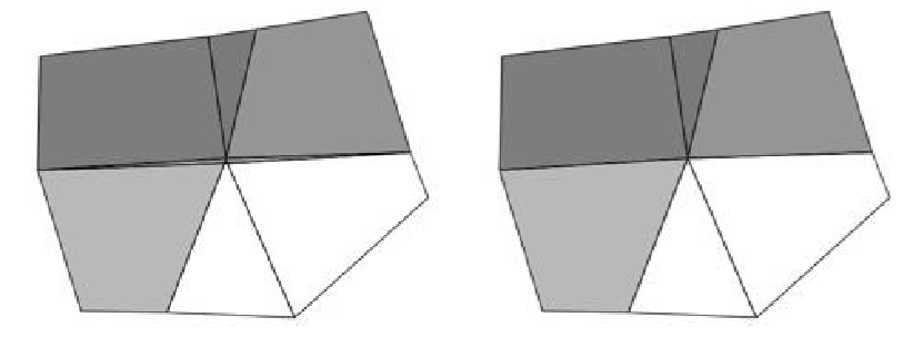
Identify Overlaps
The Identify Overlaps tool examines a mesh for overlapping planar facets. If Overlaps are detected, an option is displayed to remove the facets.
Example with Two Overlapping Facets:
- Select the Mesh with possible overlaps.
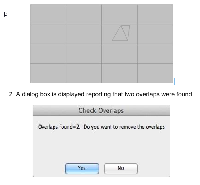
- Pressing Yes will delete the overlaps.
- Pressing No will show the overlaps as Line entities. Select Undo to remove the lines.
Check Intersections
The Check Intersections tool examines a mesh for non-planar intersecting facets. If intersections are detected, an option is displayed to remove the facets or display the intersection.
Example: 1. Select the Mesh with possible intersections.
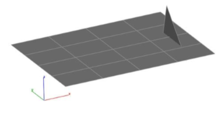
- A dialog box is displayed with the number of intersections found.
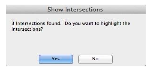
- PressingYes will create lines and points at the intersections.
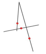
- A dialog box is displayed asking if you want to delete all facets involve with intersections.
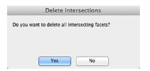
- Pressing Yes will remove the intersecting facets.
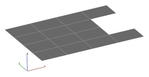
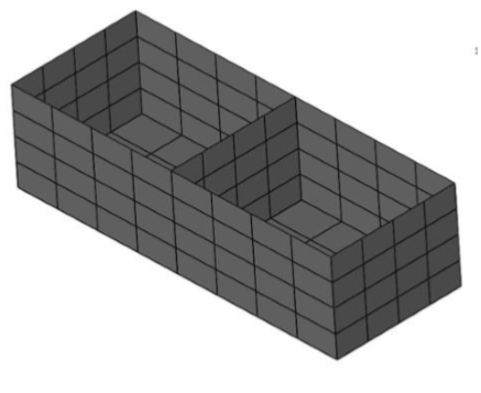
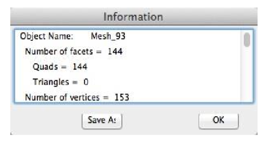
Remove Duplicated Facets
This tool removes all facets that are duplicated.
Example:
1.Select a mesh with possible duplicated facets. Original mesh has 160 facets.
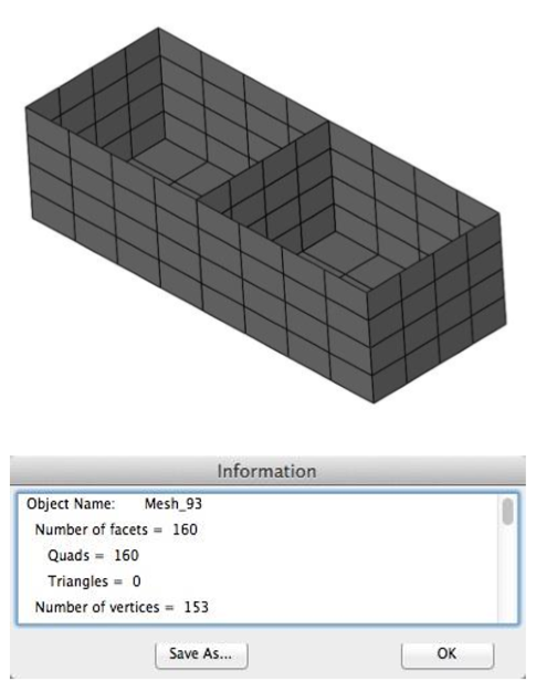
- Select Yes to remove the duplicated facets.
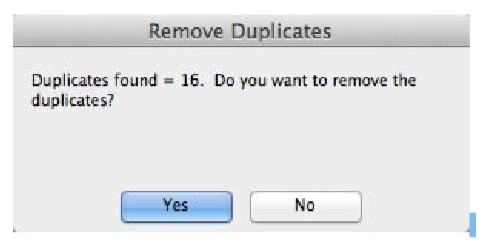
The Mesh is reduced by 16 facets to 144.
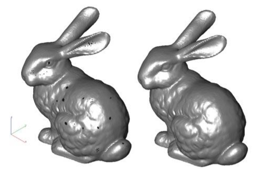
Fix Flipped Normals
This tool corrects surface normals that are not properly oriented.
Weld Vertices
The Weld Vertices tool joins vertices of a mesh. The tool has two options:
1. Entire Mesh:All vertices within the mesh within the specified tolerance are examined for joining.
2. Selected: Only the selected vertices are joined. The selected vertices are joined independent of a tolerance.
Example:
- Pick "Selected" from the pull-down menu.
- Pick two vertices that are to be joined together.
- Pick "Entire Mesh" from the pull down menu.
- Specify a tolerance from within the data entry window.
- Vertices within the tolerance are joined together.
Remove Unused Vertices
Compacts the vertices associated with a mesh to be the minimum necessary for the definition.
Close Simple Holes
The Close Simple Holes tool attempts to fill with quads or triangle holes identified in a mesh. The tool has two options, allowing for Closing All Holes or Close specific edges.
Example 1: Close All Holes
- Select a mesh to close all holes.
- The Mesh is filled with triangles or quads.
Example 2: Close Edge
- Select an edge of a mesh to close.
- Edge is triangulated and filled with facets.
- From the Option menu, select "Add Center Point" to close a mesh about an approximated hole center
Rebuild Normals
The Rebuild Normal tool recalculates all normals. The normal at a vertex is the average of the neighbors.
Example:
- Select mesh model to rebuild normals.
- Mesh normals are updated.
Flip One Normal
The Flip One Normal command prompts the user to select a specific facet to flip the normal.
Close Seam
The Close Seam tool will move vertices within a specified tolerance between two mesh objects.
Example:
- Select the Close Seam tool.
- Box selects a region that captures the two mesh vertices to check.
- Vertices of Mesh 2 that are within the specified distance are moved to Mesh.
Make Vertices Planar
The Make Vertices Planar tool takes the selected vertices and projects the vertices into a specified plane.
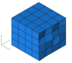
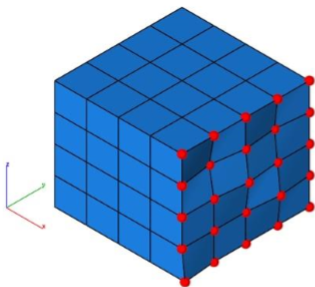
Example:
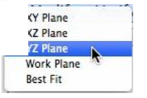
- Select the Make Vertices Planar command
- Select the YZ Projection Plane from the data entry window pull down menu.
- Select the vertices to project.
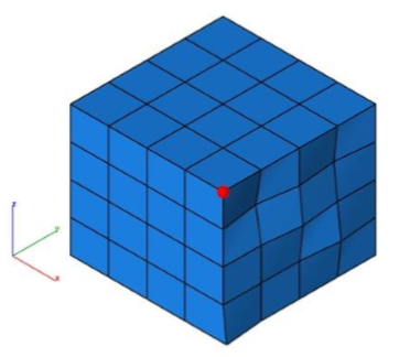
- Select a point in the projection plane.
- The mesh vertices are projected into the plane.
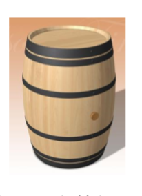
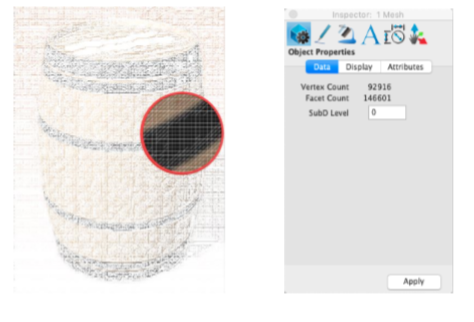
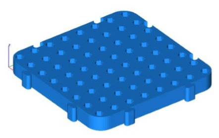
HeightMap to Mesh
This tool converts 2D Images into mesh.
Example:
- Select HeightMap to Mesh tool from PowerPack
- Select the 2D image to convert it to mesh
- The selected image is converted into mesh
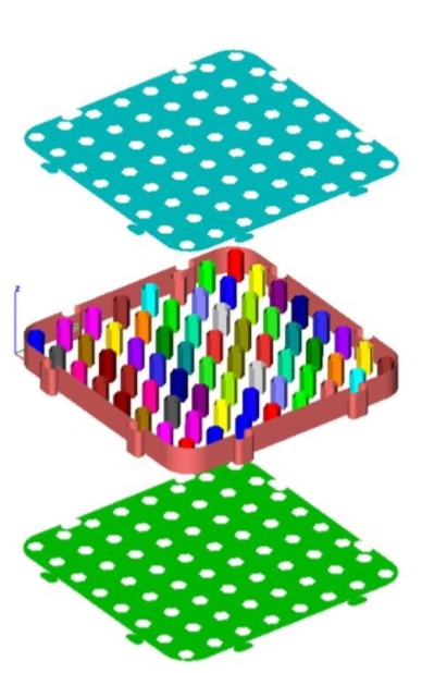
Segment Mesh
The Segment Mesh tool decimates a mesh into planar and connected components.
Example:
- Select the Segment Mesh tool.
- Select the single mesh object to segment.
- The selected mesh is converted into a collection of meshes separated by planar and connected elements. In this example 67 additional mesh objects created.
- Meshes colored by other tools to better show individual meshes
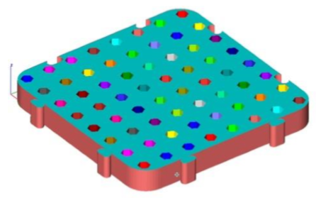
- Meshes exploded by additional tools to better show individual meshes.
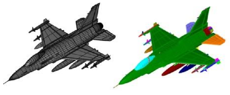
Separate All Parts
The Separate All Parts command examines the connection between facets to determine individual mesh parts. This is useful for separating individual meshes that come in as one mesh as a result of a file import such as STLIn the example below, an OBJ file representing a F-16 was imported as one mesh. Using the Separate All Parts command, 166 individual components were extracted.
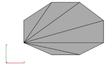
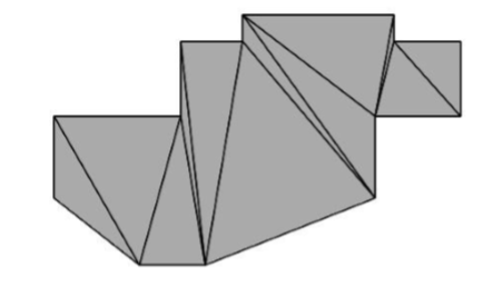
Facet From Lines
The Facet From Lines tools create triangles from a collection of connected line objects.
Example 1:
- Select the Facet From Lines tool.
- Select the lines to facet.
- Resultant triangles from lines.
Example 2:
- Select the Facet From Lines tool.
- Select the lines to facet.
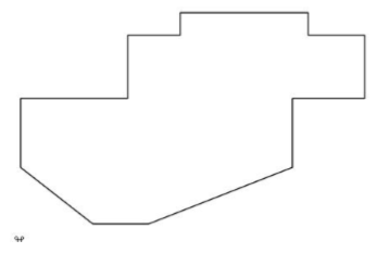
- Resultant triangles from lines
Add Facet
The Add Facet command will insert 3 or 4 sided facets into an existing mesh by the user specifying vertex locations.
Example:
- Select the Add Facet command.
- Select the mesh.
- Specify four vertex locations for first facet.
- Specify four vertex locations for second facet.
- Specify four vertex locations for third facet.
- Continue until all desired facets are added.
Delete Facet
The Delete Facets command removes facets using the box selection interface.Use Deep Select to delete one facet at a time from a mesh.
Example:
- Select the Delete Facets command.
- View the modeling in an orientation that allows you to select the facets to delete. Box select the region to delete.
- Selected facets are removed from the mesh.
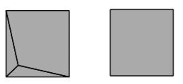
Split Facet Edge
The Split Facet Edge command takes a triangle or quad and splits an edge introducing two additional facets.
Example 1:
- Select the Split Facet Edge command.
- Select the mesh to split an edge.
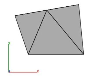
- Specify the location to split edge.
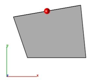
- Selected mesh is split into three triangles.
Example 2:
- Select the Split Facet Edge command.
- Select the mesh to split an edge.
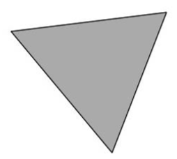
- Specify the location to split edge.
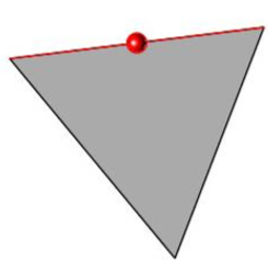
- Selected mesh is split into two triangles.
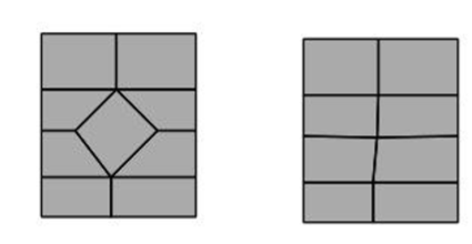
Convert To Quads
The Convert To Quads command examines a triangle mesh and recreates quads were possible.
The following cases are supported:
- Shared Edges (Two Triangles -> One Quad)
- Shared Center Vertex (Four Triangles -> One Quad)
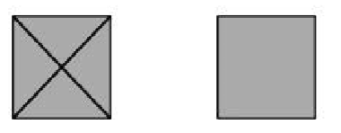
- Shared Center Vertex (Three Triangles -> One Quad)
- Doublet (Two Quads -> One Quad)
- Inner Quad Diamonds (Five Quads -> Four Quads)
Convert to Quad Demonstration Video
Converts a 47k STL file (all triangles) into a quad dominate mesh suitable for conversion to a NURB solid.
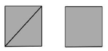
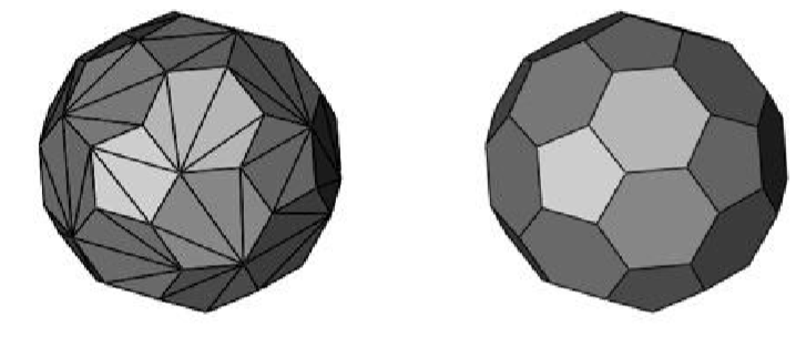
Convert To Triangles
The Convert To Triangles command changes all quads into triangles.
Example:
1.Select the Convert to Triangles command.
- Select the mesh objects to convert to triangles.
- Selected mesh is converted into triangles. A dialog box displays how many quads were converted into triangles.
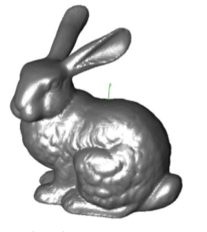
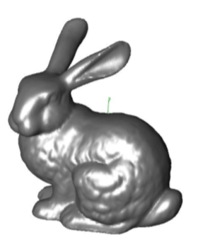
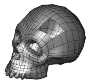
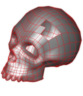
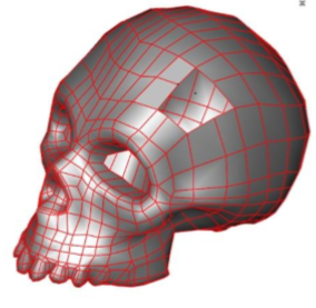
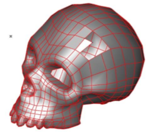
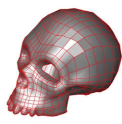
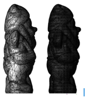
Reduce Triangles
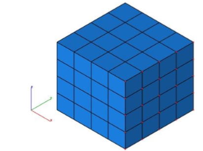
The Reduce Triangles command removes facets based on edge length size and curvature. The model below was reduced from 139,422 facets to 4,352.
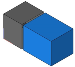
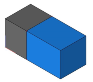
Combine
The Combine tool merges two meshes into one. Vertices that are shared are merged together.
Example:
**
- Select the Combine tool.
- Select the two mesh objects to join as one mesh.
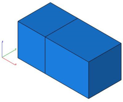
Note: The combine tool does not perform a boolean operation.
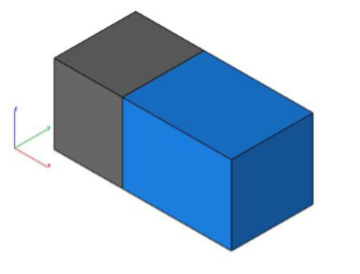
Split By Select
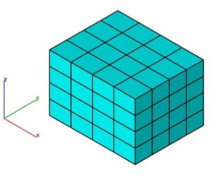
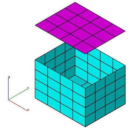
The Split by Select tool separates a collection of selected facets into a new mesh.
Example:
Combine The Combine tool merges two meshes into one. Vertices that are shared are merged together.
Example:
**
- Select the Combine tool.
- Select the two mesh objects to join as one mesh.
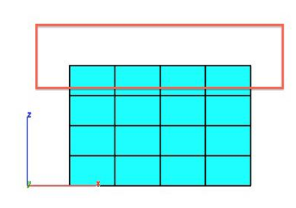
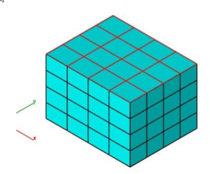
- Facets are split and two new mesh objects are created. Image below moves and colors the objects using separate tools for visualization.
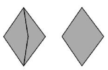
Remove slivers
The Remove Slivers command examines triangles and quads for small edges. The edges which are below the tolerance defined by the user are then disintegrated.
a) A triangle facet with a sliver edge removes the two facets that are sharing the edge.
b) A quad facet with a sliver edge is converted into a triangle.
Coordinate Compare
The Coordinate Compare tool will precisely compare a set of points to a NURB model. For data points, you can select a point cloud or a mesh object to compare with the NURB model. A NURB model is either a surface or solid.
Depending on the point data set size, this tool is computationally heavy. However, this tool is multi-processor aware and will use additional processes if they are available.
In addition to displaying a dialog box indicating the maximum deviation between two parts, line objects are created representing the minimum distance vector between the two parts.
Note: A Point cloud object is created when reading in PLY files.
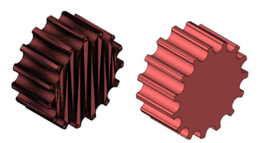
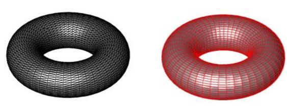
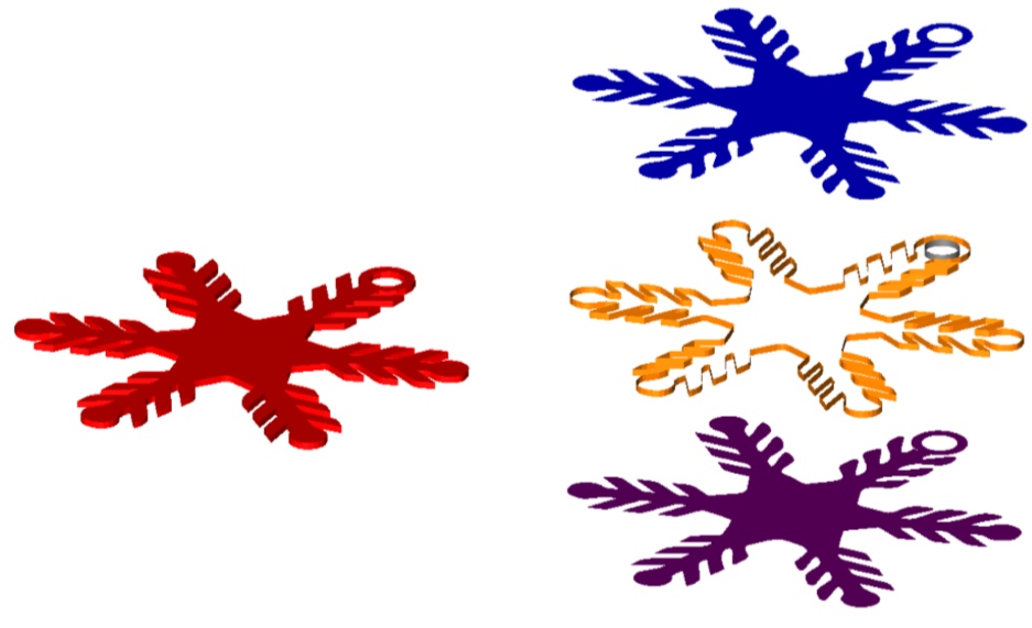
Segment Analytic
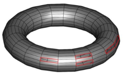
The Segment Analytic tool breaks down a complex mesh into a collection of simple analytic meshes such as planar, ruled, and revolved. The Segment Analytic tool is useful to manually convert a mesh into a solid allowing.
In the example below, the red mesh on the left is segmented and converting into three analytical surfaces, which can be manually stitched into a solid.
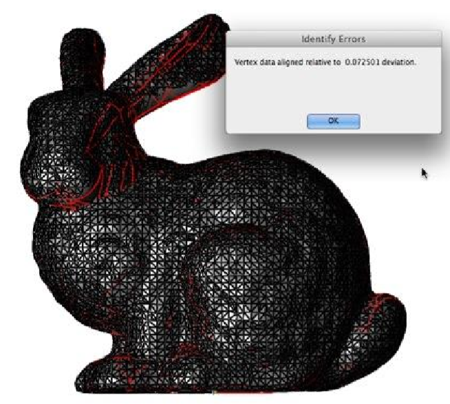
Align Mesh
The Align Mesh to Part tool will transform a mesh to lie precisely on a surface or solid. The tool will additionally display a dialog box indicating how closely the mesh represents the surface or solid.
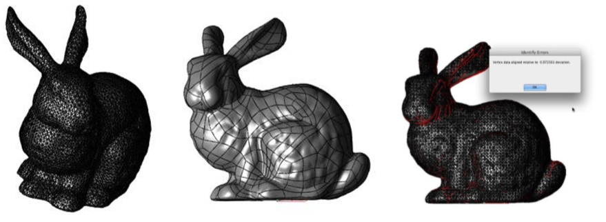
Mesh to Analytic
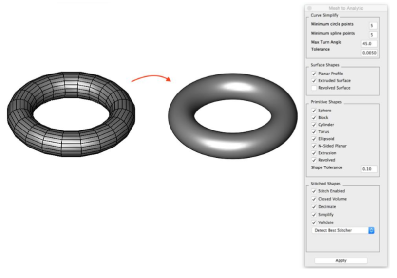
This tool converts a collection of triangular and/or quad based facets into an analytical solid created from primitives, profiles, or stitched facets. An analytical solid is a final shape consisting of planar, cylindrical, spherical, torus, and extruded faces.
Example:
- Select the Mesh to Analytic tool from the PowerPack menu.
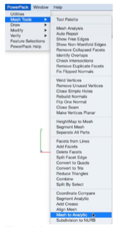
-
The Mesh to Analytic dialog box is displayed, use the default settings.
-
Select a mesh to convert.
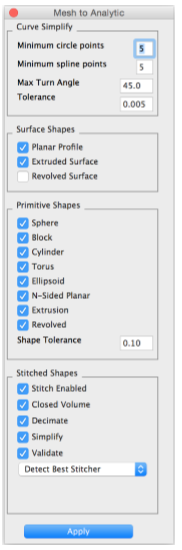
Mesh To Analytic Settings
The Mesh to Analytic dialog box provide access to all the settings for converting a mesh into a solid. The tool provides a variety of options that set attributes for tolerances, simplification types, closed/open, and validation.
Curve Simplify Minimum circle points # Points needed to represent a circle Minimum spline points # Points needed to represent spline Max Turn Angle # Angle between segments of the circle/spline Tolerance Deviation between polyline and curve
Surface Shapes Planar Profile Planar face with holes Extruded Surface Open shape extruded Revolved Surface Open shape revolved
Primitive Shapes Sphere Center point sphere solid Block Center point block solid Cylinder Two point cylinder solid Torus One point torus solid Ellipsoid One point ellipsoid solid Extrusion Extruded closed profile Revolved Close profile 360 revolutions Shape Tolerance Deviation between solid and mesh Stitched Shapes Stitch Enabled Closed Volume Decimate Simplify Validate Detect Best Stitcher
Mesh To Analytic Examples
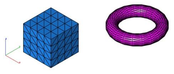
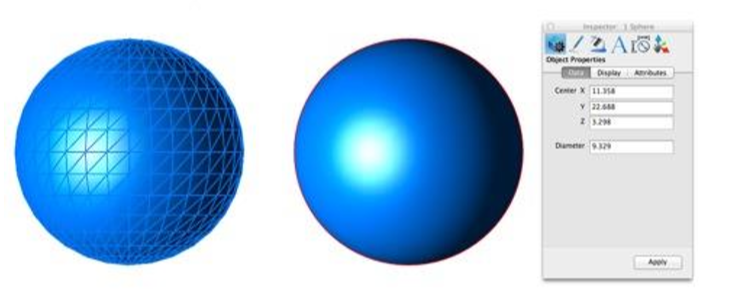
Mesh to Primitive
Sphere: Converts a collection of the triangle or quad facets into a solid sphere defined by a center point and diameter.
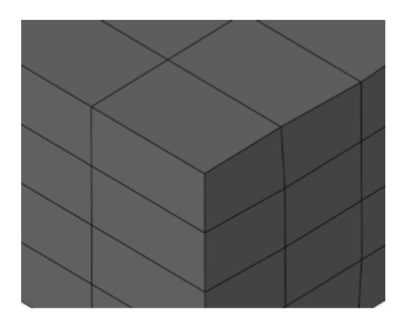
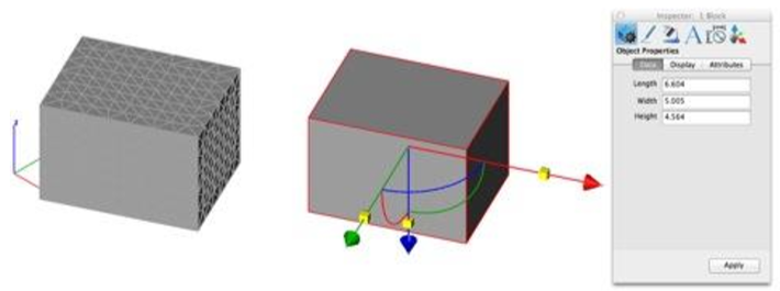
Block: Converts a collection of triangle or quad facets into a solid block defined by length, width, and height. An axis is defined to the part extracted from the orientations of the planes.
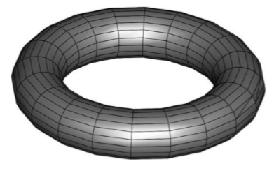
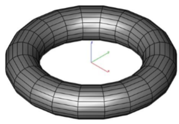
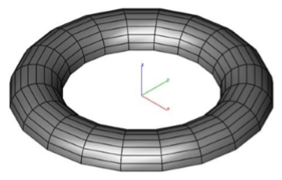
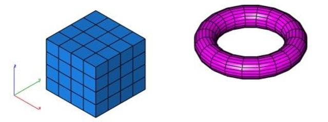
Torus: Converts a collection of triangle or quad facets into a solid torus defined by a major and minor diameter and center point.
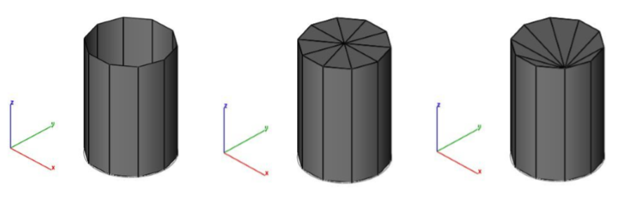
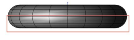
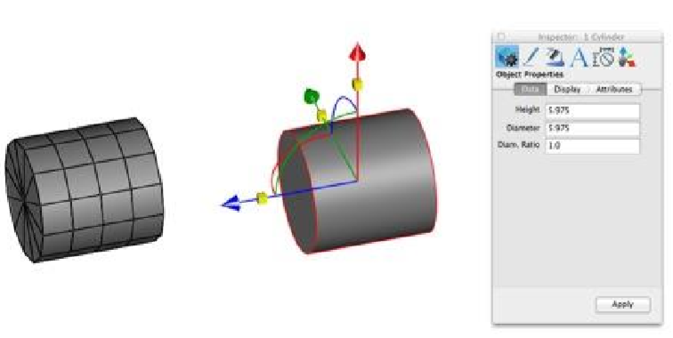
Cylinder: Converts a collection of triangle or quad facets into a solid cylinder defined by height, diameter, point at base center, and point at the top center.
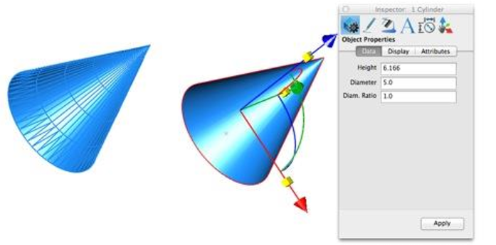
Cone: Converts a collection of triangle or quad facets into a solid cone defined by height, diameter, point at base center.
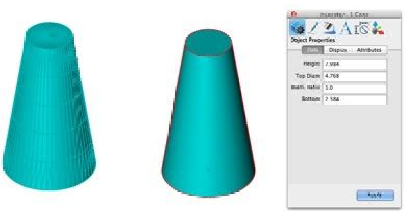
Truncated Cone: Converts a collection of triangle or quad facets into a solid truncated cone defined by height, base & top diameter, and point at base center.
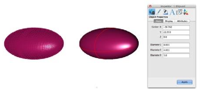
Ellipsoid: Converts a collection of triangle or quad facets into a solid ellipsoid defined by center, and three diameters. An axis is defined for the part based on the orientation.
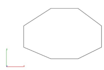
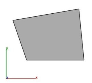
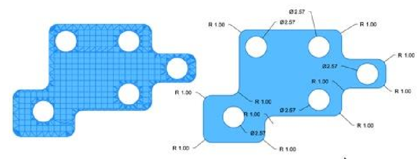
Mesh from Profile: Converts a planar collection of triangular or quad facets into a planar surface. Mesh segments corresponding to arcs and circles are converted.
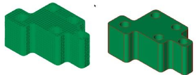
Extrusion: Converts a collection of triangle or quad facets into an extruded solid. Includes conversion of precise cylindrical holes and fillets.
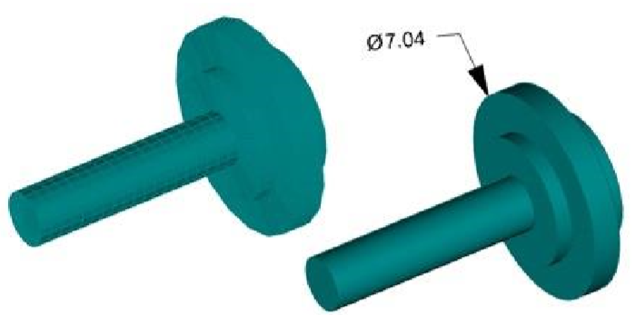
Revolved and Lathed: Converts a collection of triangle or quad facets into a revolved solid. Includes conversion of precise cylindrical holes and fillets. Only full 360-degree lathe and revolved shapes are recognized.
Mesh from Stitched Faces: N-Sided Converts a collection of triangle or quad facets into a N-Sided solid up to 20 sides.
Arbitrary Stitched: Converts a collection of triangle or quad facets into a planar faceted solid.