WorkPlanes
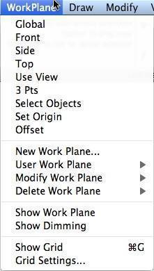
The WorkPlanes menu provides access to commands for creating, setting, and modifying the work plane. A work plane is an invisible flat surface used to define planar geometry. The work plane is also used to define the origination of the Z axis for the Snap tool.
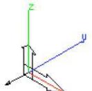
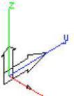
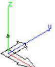
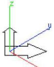
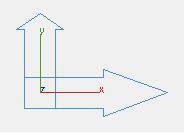
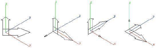
The current orientation of the work plane is displayed graphically with the WorkPlane:Show Work Plane command located in the Menu Bar. This shows a triangle representing the orientation with respect to the model axis.

Work Plane Symbol
Global
The Global option sets the work plane to the global work plane. The global work plane is the fixed, uneditable coordinate system created by SharkCAD that allows a uniform system between different files/models. This is equivalent to the world coordinate system.
Front
The Front option changes the work plane to the front plane, which is parallel to the XZ axis.
Side
The Side option changes the work plane to the side plane, which is parallel to the YZ axis.
Top
The Top option changes the work plane to the top plane, which is parallel to the XY axis.
Use View
The Use View option changes the work plane to use the view normal as the work plane z axis.
3 Pts
The 3 Pts command sets the work plane based on the input of three referenced xyz points. The three points are used to define the following information:
Pt 1 Origin of the new work plane
Pt 2 Direction of the x axis
Pt 3 Direction of the y axis
The three-point work plane command is very useful for creating oblique work planes (planes not ortho to the model coordinate system).
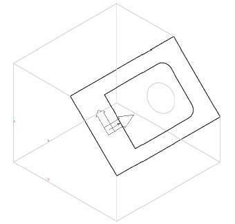
Pick Objects
The Pick Objects command sets the work plane based upon selecting curves, surfaces or faces.
The example selections below will result in setting up a new work plane.
2 Lines The two non-parallel lines define a plane from which the new work plane is created.
The origin is extracted from a point on the line.
| Circle | The circle normal defines the work plane orientation. The user selected location on the |
|---|---|
| circle defines the work plane origin. | |
| Face | The face normal is used to calculate the work plane orientation. The origin is the user |
| selected point on the circle. |

Set Origin
The Set Origin command moves the current work plane to the specified location.
Offset
The Offset command moves the work plane parallel to the current work plane xy axis.
New Work Plane
The New Work Plane command creates a work plane by dialog box field values.
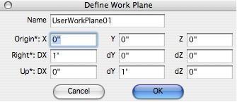
Name Specifies the work plane name. This name is used in subsequent commands such as specifying a user work plane or deleting a work plane.
Origin Defines the work plane x, y, z origin.
Right Defines the x axis for the work plane.
Up Defines the y axis for the work plane.
The last three items have an asterisk, which means you can reference these values with the Snap tool in the drawing window.
User Work Plane
The User Work Plane option displays a menu listing all the user defined work planes. Pick the desired work plane and this will set the current work plane to the selected item.
Modify Work Plane
The Modify Work Plane command displays a menu listing all of the user defined work planes.
Selecting a name will display the dialog box used to create a new work plane.
Delete Work Plane
The Delete Work Plane command will display a menu list of all user defined work planes.
Select the item you desire to delete. This operation is not undoable.
Show Grid
The Show Grid command turns on or off the grid. For a full description of the grid parameters see the discussion for the grid in the File:Preferences:Grid portion of this document.
Show Work Plane
The Show Work Plane command toggles the work plane symbol on and off.
Show Dimming
The Show Dimming command provides a means to dim objects that do not lie in the work plane. This tool aids in visually identifying objects in or out of the work plane. This command is a toggle command that turns on or off this feature.
Work Plane Snapping
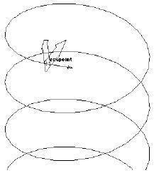
A little known shortcut for changing the work plane is accomplished by pressing the ‘c’ key at an identified snap location. Repeatedly pressing the ‘c’ key will toggle the work plane to different orientations at the snap location.
SharkCAD goes one step further with work plane snapping with the addition of aligning the work plane to be perpendicular to a curve. The work plane will snap perpendicular to a curve if you have a snap identified as either on, end, vertex or midpoint.
Grid Settings
The Grid Settings command displays a dialog box used to set a variety of attributes related to the grid.
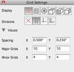
Display The Display icon row contains six grid modes that include
No Grid
Rectangular
Polar
Isometric Top
Isometric Left
Isometric Right
Divisions The Division icon row provides 4 methods to display the grid line divisions.
No Divisions
Sub Divisions
One Offset
Two Offsets
Spacing The Spacing value defines the distance along x and y between major grid lines.
Major Grids The Major Grids setting defines an integer value for the number of major gridlines along the x and y axis.
Minor Grids The Minor Grids setting defines an integer value for the number of major gridlines along the x and y-axis.
Polar Angle A float point value that is used while in Polar mode for the Major grid angle.