(Available in TurboCAD Deluxe and TurboCAD Pro)
TurboCAD supports nine surface types that are created by referencing curves. From left to right across the surface tool palette they are:

- Infinite Plane
- Net
- Ruled and Skin
- Cover
- Revolution
- Extrude
- Swept
- Bi-rail
- Tube
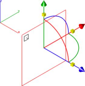
Infinite Plane
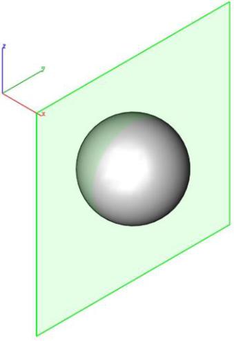
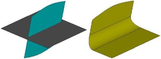
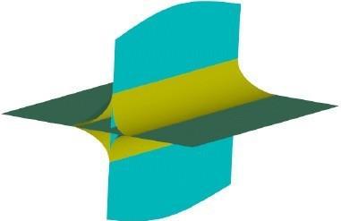
The Infinite Plane Surface is the simplest surface supported by TurboCAD. An infinite plane is defined by a location and normal. The plane surface is useful for generating cross- sections through meshes, surfaces or solids
The infinite plane has five creation methods:
X- Station
Create a plane with normal X=1, Y=0, Z=0
Y-Station
Create a plane with normal X=0, Y=1, Z=0.
Z-Station
Create a plane with normal X=0, Y=0, Z=1.
Normal & Location
Create an arbitrary plane by specifying the location andnormal.
Three Points on Plane
Specify a plane by three points. Normal is calculated from the threepoints.
Using the Infinite Plane Surface tool
- Select the infinite plane sub type (x--station, y--station, etc.).
- Click at the location of the plane.
Infinite Plane
Sizing Infinite Planes
The default Infinite Plane Surface display is a small rectangle with an arrow indicating the direction. The size can be made larger by selecting the plane with the Gripper and scaling.
By default, the Infinite Plane is completely transparent. Right click on the plane to add partial transparency. Changing the Infinite Plane color will also change the transparency color.
Net Surface
The Net Surface is created from a collection of m x n curves. The curves may be combinations of lines, splines, arcs, ellipses, conics or circles. Each curve must be a single curvature continuous curve. No groups (composited curves) are allowed. A point is allowed at either the start or end of the surface. The supplied curves do not need to be planar and do not need to touch.
Using the Net Surface tool
- Hold the Shift key and pick the curves defining the m direction. Release the Shift key when done selecting.
- Hold the Shift key and pick the curves defining the n direction. Release the Shift key when done, to create the net surface.
Net Surface
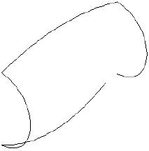
The net surface does not require that the curves intersect. This means that nets such as the one shown below are possible.
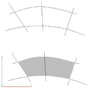
Overlapping Curves Net Surface
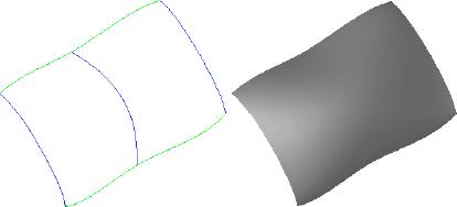
Ruled Surface
A Ruled Surface has straight spanned between each section. Sections can be of any curve type. This tool is available from the sub-tool palette.
Using the Ruled Surface tool
- Hold the Shift key and pick the curves.
- Release the Shift key when done selecting.
Ruled Surface
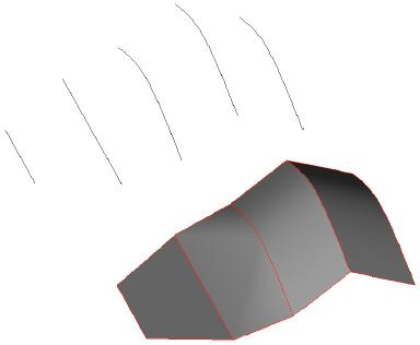
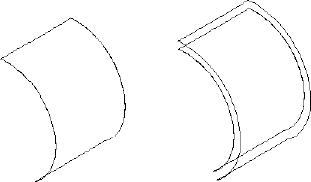
Skin Surface
A Skin Surface fits a network of NURBS patches to a collection of curve cross sections. The curves can either be all opened or all closed. Curves suitable for skinning include lines, arcs, circles, ellipses, conics, and splines. Each curve must have continuous tangents (no polylines) and be oriented in the same direction. If the curves have different directions, the resulting surface will twist from section to section. Also, sections cannot share an endpoint (each section start and end must be a unique position in coordinate space). This tool is available from the sub-tool palette.
Using the Skin Surface tool
- Hold the Shift key and pick the curves (line, spline, arc, circle, ellipse).
- Release the Shift key when done selecting.
CurvesSkinned Surface
By default, the skin tools will Auto Align curves such that their direction and orientation are irrelevant. If you come across a condition where the auto align is turned off or does not apply you will need to manually align each curve section. To do so, use the Verify: Direction command located in the Menu Bar to examine curve direction. You can use the Edit: Change Direction command to reverse the orientation of a curve.
Middle curve
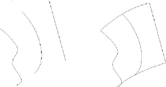
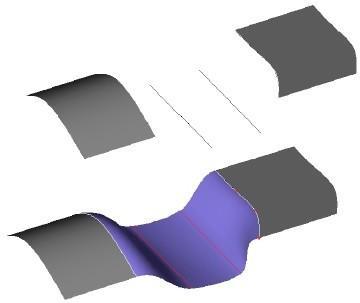
Guide Skin Surface
A Guide Skin Surface is identical to a skin surface with the addition of an unlimited number of edge guide curves. The guide curves control the surface’s edge shape between the skin sections. Either one or both surface edges can be guided. Each guide curve must go through a point on the skin profile curves. Curves suitable for guides include lines, arcs, circles, ellipses, conics, and splines. This tool is available from the sub-tool palette.
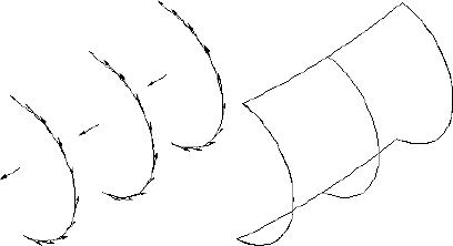
(a) Skin Surface(b) Skin with One Guide(c) Skin with Two Guides
Skin Surface Example
In the figure above are three skin surfaces created from the same three arcs. Figure (a) is the skin surface without guide curves. Figure (b) shows the same three arcs with a single spline guide curve. The spline goes through the starting point of each circle and the slopes are modified. Figure (c) shows a skin with two guide curves. One is at the beginning of each curve; the other is at the midpoint. The slopes on each spline have been modified to produce an unusual surface. The figure illustrates how the intermediate shape of a skin is drastically controlled using guide curves.
Using the Guide Skin Surface tool
- Hold the Shift key and pick 2 or more skin profile curves (line, spline, arc, circle, ellipse). Release the Shift key when done selecting.
- Select the edge guide curve(s). Hold the Shift key to select multiple curves.
Skin Options
Both the Skin Surface and Guide Skin Surface tools provide many options that can be used at the time of creating a skin surface. After a tool is active, click the Options button on the Prompt window
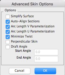
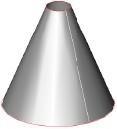
Simplify Surface
The Simplify option simplifies the created surface to a conical surface, if applicable. If all of the cross sections lie on a conical surface (plane, cylinder, cone, sphere or torus), the conical surface is created instead. The value of 0.000001 is used to determine whether or not the cross section lies on an analytical surface (planar, conical, spherical or toroidal). The default is not simplified.
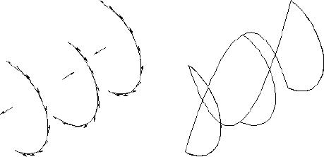
Auto-Align Sections
The Align Sections option may be used to allow the skinning algorithm to align the direction of the curves in the selection list. Closed loops of wires can also be aligned. The default is aligned.
Arc Length Parameterization
The Arc Length option is used to choose arc length or iso-parametric parameterization of the skinning surfaces. In iso-parametric parameterization, the surface parameter in the v direction follows the cross section curves. In Arc Length Parameterization, the surface parameter follows lines of constant length.The default is arc length parameterization.
Minimize Twist
The Twist option may be used to minimize the twist of the surface produced. Twist minimization aligns closed curves such that the start of the second curve is aligned to the start of the first curve. Even if a body’s shape is unaffected by twisting, a surface with a twist could produce unexpected results when faceting and rendering. By default, twist minimization is on. Twist minimization is also an involved calculation that some users may not want to have carried out.
Perpendicular Skin
The take-off vector is a tangent vector going out of the starting edge or surface and into the skinned surface. The Perpendicular option is used to specify the direction of the take-off vector, perpendicular to the edge. The default is in the loft direction, because a perpendicular take-off vector can cause self-intersections to the surface.
Default SkinningPerpendicular Skinning
Perpendicular Skin Option
Draft Angle
Skinning with draft angles provides the ability to control the take-off vectors of the two outer skinning profiles. The “draft” angle is defined as an angle off the plane of the wire at every point along the skinning profile. In addition to the user supplying the angle itself, one may also supply a magnitude for the take-off vector. The draft angle and magnitude are constant for the entire profile. However, one may apply different draft angles to the two outer profiles. In addition, skinning with draft angles supports open and closed profiles and skinning to a point. When skinning to a point, the algorithm constructs its own normal vector. The outer profiles must be planar when not degenerate. Use the Edit Object dialog box to access the skin magnitude.
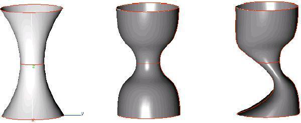
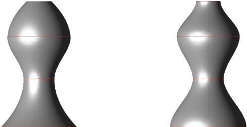
Standard Skin
Between Two Circles
Various combinations of
Draft Angles and Draft Magnitudes
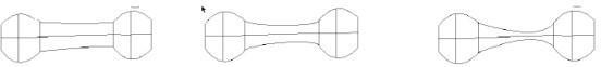
Skinning Two Circles
In the figure above, note the different number of shapes that can be obtained from the same two circles for a skinned surface. To access the skin parameters, select the surface and edit the parameters in the Inspector.
Editing Skinned Surfaces
The Inspector dialog contains the various options used for creating the skin surface. You can change any of these options and have the surface regenerate to the new option.
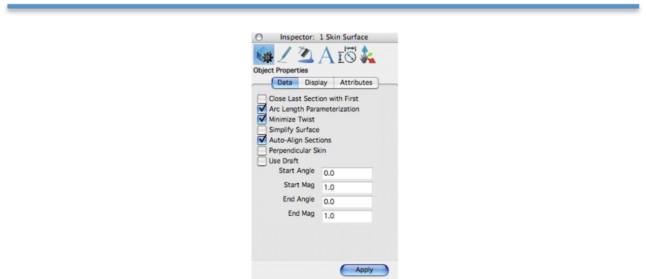
Skin Properties
Cover Surface
The Cover Surface is an extremely versatile and powerful utility for creating a surface from curves connected end to end. Curves suitable for cover surfaces include arcs, circles, lines, splines, ellipses, and conics. Curves are not required to be in a plane. Each individual curve must have continuous curvature (no polylines or groups). If the curves all lie in the same plane, a simple planar surface with boundaries is created. If the curves lie out of plane, a Gregory surface is fit to the boundary curves.
The Cover Surface tool also has the ability to cover planar bodies that include interior cutouts. The cover automatically updates according to fillets and chamfers, and if a hole is removed or resized.
Covers must be created from curves connected end to end. If one or more of the curves are not connected, TurboCAD displays the message “can only cover closed wires”. You can force wire ends to precisely close with one of two commands. The first command is the Move Selected Points tool, located in the main tool palette under transforms. The second command is connected curve ends located in the tool palette under Curve Utilities.
Invalid Curves for Cover
Using the Cover Surface tool
- Hold the Shift key and pick the curves (line, spline, arc, circle, ellipse).
- Release the Shift key when done selecting.

Cover Surfaces
Covering a surface with holes
- Drag a selection window around the entire surface you want tocover.
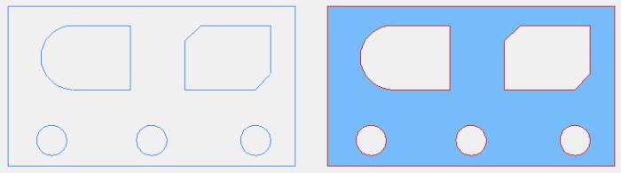
Surface with holesCovered surface with holes
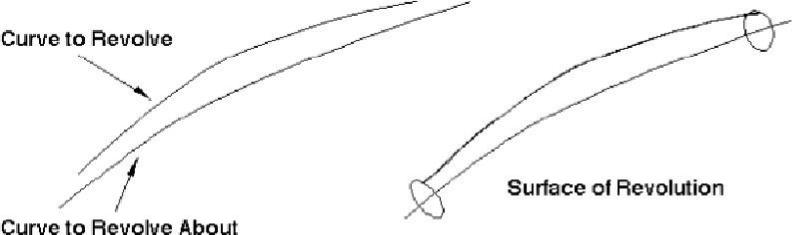
Surface of Revolution
The Surface of Revolution is used to model axis symmetric objects. The designer can choose from one of two methods:
- Revolve About 2 Points
- Revolve About Curve
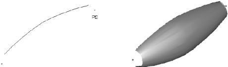
Two Point Revolved Surface
The surface of Revolution About 2 Points option will revolve the curve a user specified angle about an axis created from two user specified points.
Using the Two Point Revolved Surface tool
- Hold the Shift key and pick the curves to revolve (line, spline, arc, circle, ellipse).
- Release the Shift key when done selecting.
- Specify the angle of revolution in the Data Entry Window.
Click two points defining the axis of revolution.
Surface of Revolution
The direction of the angle is defined by the order of the points defined for the axis. Use the right-hand rule to determine the direction that the surface will revolve. If the axis intersects the lathe curve, TurboCAD displays the error message below. Your only course of action is to pick a new non- intersecting axis.
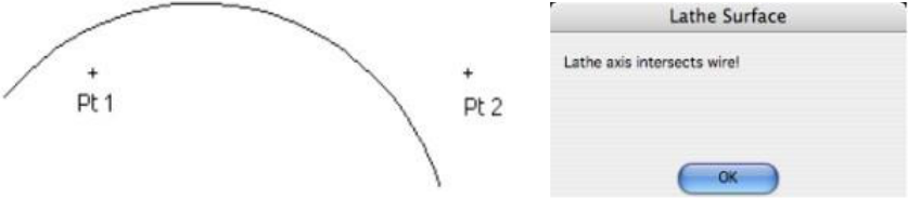
Intersecting Axis Error
Curve Revolved Surface
The second method revolves a curve about another non-linear axis such as a curve. The curved axis must be as long or longer than the curve you are revolving
Using the Curve Revolved Surface tool
- Pick one curve to revolve (line, spline, arc, circle, ellipse).
- Type in the angle of revolution in the Data Entry Window.
- Pick one curve to revolve about (line, spline, arc, circle, ellipse).
Revolve About Curve
Extrude Surface
The sweep 2 points surface sweeps a curve, collection of curves or group along two user supplied points that define the direction and length of the sweep.
Using the Extrude Surface tool
- Pick one or more curves to sweep (line, spline, arc, circle, ellipse, groups).
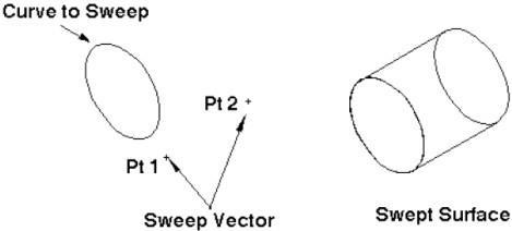
Click two points that define the direction and length of the sweep from the curves.
Sweep Surface 2 Points
The resulting surface is associative to the original sweep curve. Changing the curve will automatically update the surface. You can also edit the sweep length and direction with the Object Info command; this opens the Inspector.

One Rail Sweep Surface
The One Rail Sweep Surface sweeps a curve, collection of curves or group along a user supplied rail curve. The resulting surface is associative to both the path and sweeps curve. Modifying either will automatically update the associative sweep surface. The Sweep One Rail command has two pull downs for options in the prompt line. The first pull down controls how the profile orientation sweeps as it is moves along the rail. It contains the following three options.
•
•
•
Sweep in Place (profile is not translated or aligned to path).
Sweep Perp (profile is translated and aligned perpendicular to path).
Sweep Rigid (profile orientation is maintained regardless of pathtangent).
The second pull down controls how the profile is terminated. It contains the following three options.
•
•
•
Curve extents (profile sweeps across entire curve extents).
To Body (profile is terminated at a surface or solid).
Between Points (user specifies two points on the path).
Sweep Perpendicular rotates the sweep profile to be perpendicular to the take off path. Sweep in Place leaves the sweep as is; no aligning of the profile occurs with this option. Sweep to Entity sweeps the profile along the given path and terminates to a reference surface or solid.
Using the One Rail Sweep Surface tool
- Pick one or more curves to sweep (line, spline, arc, circle, ellipse, groups).

Pick one curve for the rail path.
Sweep Surface One Rail

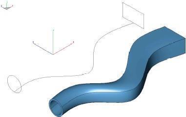
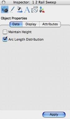
Two Rail Sweep Surface
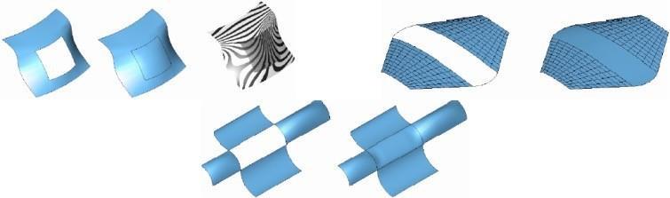
The Two Rail Sweep Surface tool creates a swept surface by sweeping an open or closed curve between two rail curves. The rail curves define the orientation and scale of the surface as it moves between the two curves.
The Inspector offers two options after the surface has been created. Select the surface, and the options are available on the Data tab.
Using the Two Rail Sweep Surface tool
- Pick one or more curves to sweep (line, spline, circle, ellipse, groups).
- Pick the first rail path.
- Pick the second rail path.
- Hold the Option key at step one if you want to maintain the profile height as it is swept.
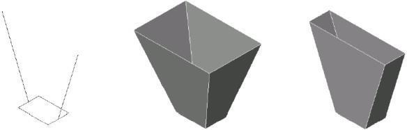
Original CurvesSweep NormalSweep Maintain Height
Sweep Surface Two R

Tube Surface
Creates a tube or pipe surface along a curve with a given radius.
Using the Tube Surface tool
- Type in a tube radius in the Data Entry Window.
- Pick the tube path which is the tube centerline.
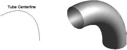
Tube Surface
Surface Features
(Available in TurboCAD Pro)
The Surface Feature tool palette contains surfaces that are created by referencing other surfaces in addition to other optional parameters. Example surface features include:
•
•
•
•
•

Offset
Loft
Draft
Fillet
Tangent Cover
Offset Surface
Offset surfaces maintain a constant distance normal to the parent surface. An offset surface is created by first selecting the parent surface and specifying the offset surface. The direction of the offset is in the direction of the surface normal. You can specify negative offsets. Typically, you cannot offset a surface a distance greater than the smallest radius of curvature.
Using the Offset Surface tool
- Type in an offset value in the Data Entry Window.
- Pick the surface to offset from.
- Type a negative into the Data Entry Fields if the offset is desired on the opposite side.
Offset Surface

Loft Surface
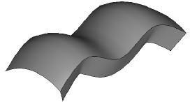
The Loft Surface creates a tangent continuous surface between one or two surfaces. The Loft Surface also accepts a bulge factor which influences the strength of the slope coming off of the referenced surfaces.
Using the Loft Surface tool
- Hold the Shift key and pick the starting surface edge to reference.
- Hold the Shift key and pick intermediate curves
- Pick the ending surface edge for reference.
Type in bulge values to adjust tangent magnitude.
Lofted Surface
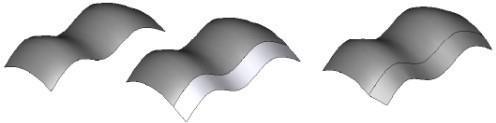
Once created, the blend surface can be modified with the Inspector. The start bulge factor controls the magnitude of the slope from the starting edge, whereas the end controls the slope influence at the end curve. The reverse curve options are provided to fix twisting of the blend surface resulting from different edge directions.
Bulge = 0.25Bulge = 1.0Start Bulge=3,
End Bulge=0.5
Bulge Factor Examples

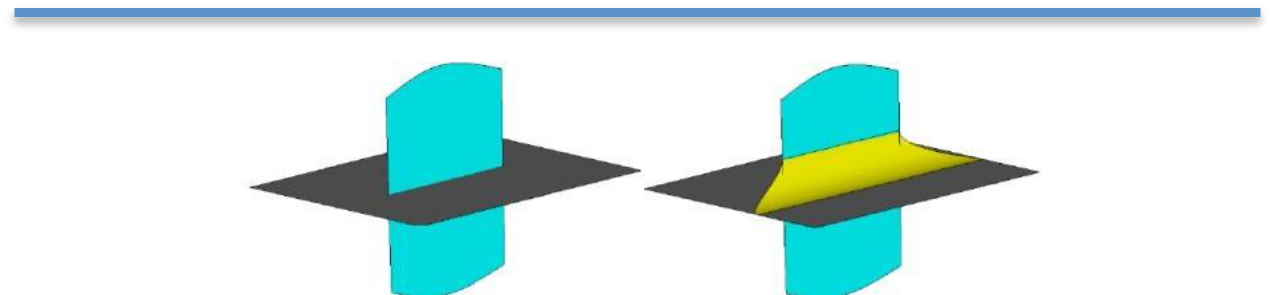
Draft Surface
The Draft Surface tool creates a surface at an angle relative to a referenced surface. For example, zero degrees will create a surface tangent to the referenced surface.
Using the Draft Surface tool
- Use the Data Entry Fields to specify the draft angle and surface length.
- Pick the starting surface edge.
Draft Surface
The draft surface also has an option that controls how the surface slope is calculated with respect to the referenced surface. In the example below, the first draft is aligned with the edge and the second is aligned with the surface.
Draft Surface Align Option

Fillet Surface
The Fillet Surface tool will create a smooth radial surface between two surfaces. Use the option to trim the surfaces back to the fillet.
Using the Fillet Surface tool
- Use the Data Entry Fields to specify the fillet radius.
- Pick the first surface.
- Pick the second surface.
Fillet Surface
Using the Fillet Surface tool (Trim Option)
- Use the Data Entry Fields to specify the fillet radius.
- Press the option key.
- Pick the first surface.
- Pick the second surface.
Fillet Surface-Trim Option
The Fillet tool automatically determines the quadrant for the fillet, based on where the user selects.
Fillet Surface-Auto Quadrant Selection

Tangent Cover Surface
(Available in TurboCAD Pro)
The Tangent Cover Surface creates tangent boundary surfaces. The resulting surface is tangent to selected surfaces. This tool will accept any combination of four curves and surfaces. The tool also recognizes selected surface edges without exploding first to edges. The resulting surface maintains its associativity to the parent curves and surfaces.
Example Tangent Cover Surface
Using the Tangent Cover Surface tool
- Pick surface edges or curves that define a closed loop.
- Use the Data Entry Field to influence the effect of the tangent vector.
Surface Utilities
There are two palettes of surface utilities if you are using TurboCAD Pro and one palette if you are using TurboCAD Deluxe. These two palettes contain tools useful for manipulating and extracting information from existing surfaces.
Surface Utilities (Available in TurboCAD Deluxe and TurboCAD Pro)

•
•
•
•
•
•
•
Cut Section
Project Curve Surface
Surface/Surface Intersect
Curve/Surface Intersect
Silhouette Curve
Explode Curve
Project Curve to Plane
Local Surface Utilities (Available in TurboCAD Deluxe and TurboCAD Pro)
Advanced Surface Utilities (TurboCAD Pro)