Dimension Properties
Annotations are a critical part of creating any drawing. Dimensions, tolerances, and other annotations allow the user to clarify complicated parts, components or assemblies.TurboCAD allows the user many powerful types of annotations, including linear and angular, dimensions and tolerances, balloons, witness lines, and center marks. This chapter presents descriptions of these powerful tools and how they integrate into your drawing.
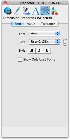
Dimension Text
The Dimension Text is controlled from the Font tab. You can change the text font, size, and style. You can limit the font selections to only those fonts used in your drawing; to do so, select the Show Only Used Fonts checkbox.
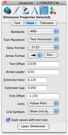
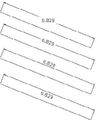
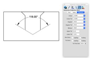
Dimension Values
The Values tab affect the actual value. Here you can change properties such as size, orientation, and position.
Standards Layouts
The Standards Layouts menu controls a collection of predefined attributes that define a particular standard. Example attributes include arrowheads, text placement, and additional spacing values.
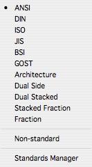
Standards Manager
The Dimension Standards dialog box allows you to create custom standards for dimension settings.
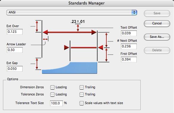
Standards
A list of predefined and user-defined standards.
Text Offset
The text height above the leader line.
Next Offset
The distance between successive leader lines. This value is relevant for baseline dimensions.
First Offset
The distance between the object dimensioned and the leader line.
Arrow Leader
The distance for the arrow leader line. Used only when the arrows are placed outside.
Ext. Over
The distance above the leader line along the extension line.
Ext. Gap
The distance between the dimensioned point and the beginning of the extension line.
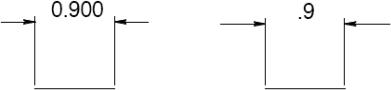
Dimension Zeros
Checkbox indicating whether to include leading and trailing zeros for the dimension value.
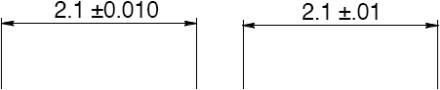
Tolerance Zeros
Checkbox indicating whether to include leading and trailing zero for the tolerance values.
Tolerance Text Size Tolerance size as a percent of the dimension text size.
Save The save button will store all settings to the current user defined standard. Note: Save is available only for user defined standards. You cannot overwrite or change predefined standards.
Save As Saves the existing settings to a new user defined standard
Delete Deletes the current user standard for the standards drop-down list. Note: You can only delete user define standards. You cannot delete predefined standards
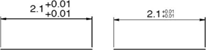
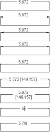
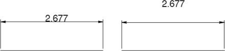
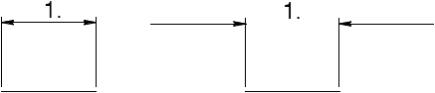
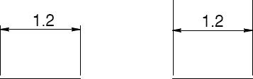
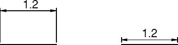
Text Placement
The Text Placement options apply to both linear and angular dimensions. The four options, Horizontal, Break-In, Over, and Under placements control the placement of the dimension text relative to the leader line.
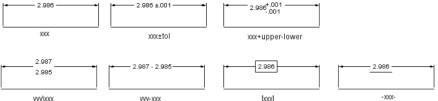
Value Format
The seven options in the Format menu control the Value Format of the dimension text. These formats apply to both linear and angular dimensions. The value format is included within the text portion of the dimension.
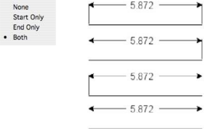
Arrow Format
Choose the endpoint format and size for dimensions.
Text Offset
Used to control the distance between the text and the extension line for over or under text formatted dimensions.
Arrow Leader
Specifies the minimum length for a leader line in the dimension. If there is not enough room, the arrows are automatically flipped to the outside.
Extension Over
Specifies the distance that the extension goes about the leader line.
Extension Gap
The distance between the dimensioned point and the beginning of the extension line.
First Offset
Specifies the leader line distance above the measured points.
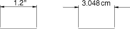
Units
The Units pull down provides a means to mix units in a drawing.
Specifying units allows you to use various units of measure throughout a single design.
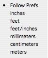
Unit Symbols
The Unit Symbols pull down allows you to specify how the unit of measure symbol is displayed (or not displayed) for a selected dimension. There are three options:
- Follow Prefs- uses the Show Dimension Unit Symbols setting in the Preferences: Unitsdialog.
- Show Unit Symbol- displays the unit of measure symbol for the selected dimension.
- Hide Unit Symbol- hides the unit of measure symbol for the selecteddimension.
Scale Values with Text Size
This checkbox will enable automatic scaling of all dimensions’ values (arrow head sizes, offsets, leader lengths) when the text size is changed.
Layer Creation
The Create Layer menu item sets the layer that dimensions are initially assigned into. Use the Edit: Change Layer to assign a new layer to a dimension.
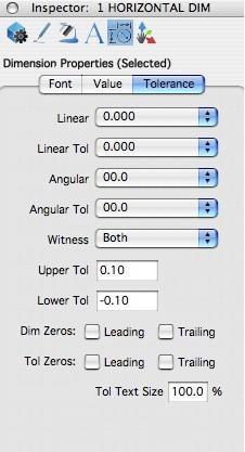
Dimension Tolerance
The Tolerance tab affects the limitations that are applied to the actual dimension value. Setting the Tolerance properties can help maintain realistic or consistent dimension values and formats throughout a design.
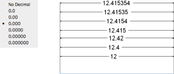
Linear
The Linear menu provides a means to specify the number of decimals for the linear value of the dimension.
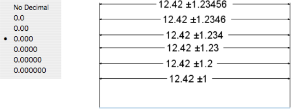
Linear Tolerance
The Linear Tolerance value controls the number of decimals used in the tolerance portion of a dimension.
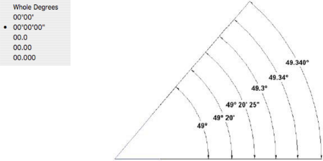
Angular
The Angular menu controls the display format for angular dimension value. Format options are available for degree/minute/second formats as well as decimal versions.
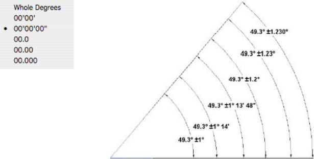
Angular Tolerance
The Angular Tolerance menu controls the display format for the tolerance portion of the angular dimension.
The Angular Tolerance user interface was updated to dynamically provide input from the Inspector dialog box.
Highlights of the Angular Tolerance Tool:
—Select an angular dimension
—Change tolerances
—Entity updates in real time for selected tolerance
Witness
This option turns on or off the Witness Line for a dimension.
Upper Tol
Defines the position of the upper-level tolerance value, if the applicable value format is selected.
Lower Tol
Defines the position of the lower-level tolerance value, if the applicable value format is selected.
Dim Zeros
Specifies whether zeros will be removed if they are leading or trailing in the dimension text.
Tol Zeros
Specifies whether zeros will be removed if they are leading or trailing in the tolerance text.
Tol Text Size
Specifies the size of the tolerance text as a percent of the dimension text.