Mesh Modeling
Quad mesh modeling tools allow you to create models that can be quickly pushed or pulled into complex shapes. These tools create quad meshes, which are suitable for use with subdivision modeling techniques.
Meshes are drawn and edited with a polygon control cage. You can subdivide the mesh to increase or decrease the level of smoothness and adjust the availability of quads, which can be edited using the Deep Select tool and Gripper. Mesh properties are available in the Inspector (on the Data tab), where you can view the vertex count, facet count, and edit the sub-division level.
- Once a mesh model has been created, users can:
- Print a 3D model using stereolithgraphy.
- Share data with subdivision applications using OBJ and DWG.
- Use the Edit Convert command to change into a precision solid.
Points Mesh
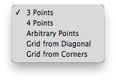
The Points Mesh tool creates a planar mesh from the following methods: 3 Points, 4 Points, Arbitrary Points, and Grid. After the tool is selected, the options drop-down becomes available in the Prompt Window.
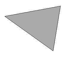
3 Points
This option creates a planar mesh based on three user-defined points.
Creating a 3 Points Mesh
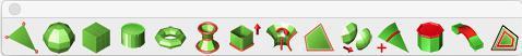
- Select the Point mesh tool from the toolbar.
- On the Prompt Window, choose 3 Points from the Method drop-•down.
- Click three points to define the shape.
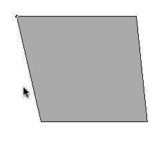
4 Points
This option creates a planar mesh based on four user-defined points.
Creating a 4 Points Mesh
- Select the Point mesh tool from the toolbar.
- On the Prompt Window, choose 4 Points from the Method drop-•down.
- Click four points to define the shape.
Arbitrary Points