Dimension
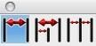
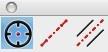
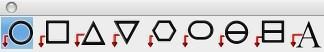
There are eleven tools for creating dimensions. From left to right, these tools are:
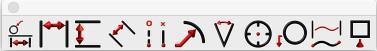
- Smart Dimension
- Horizontal
- Vertical
- Parallel
- Ordinate
- Radial and Diametrical
- Angular
- Center Mark
- Balloon & Callout
- Length Along Curve
- GDT Callout
- Area Dimension
The Smart Dimension tool creates an associative link between the dimension and any referenced curve. This means that modifying the curve will automatically update the smart dimension. The other dimension tools do not preserve a relationship between geometry and the dimension.
Dimension Text
You can specify the dimension text or use the # symbol to automatically fill the field based on the measured value. The text is controlled on the Prompt window.
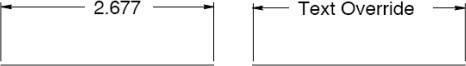
Dimension properties, such as format, orientation, and more, are controlled on the Inspector.

Smart Dimension
The Smart Dimension tool creates horizontal, vertical, parallel, radial or diameter dimensions based the object type selected and where you move your mouse. Dimensions created with this tool are associative to the curves referenced. Modifying the shape of the curve will automatically update the dimension.
Using the Smart Dimension tool (Example 1--HVP Dimension)
- Position the cursor over a line such that the Snap tool says “on”. Click the mouse.
- Move the cursor to place a horizontal, vertical or parallel dimension.
- Click at desired location to accept the final dimension.
Using the Smart Dimension tool (Example 2--Diameter Dimension)
- Position the cursor over a circle such that the Snap tool says “on”. Click the mouse.
- Move the cursor to place a diameter dimension.
- Click at desired location to accept the final dimension.
Using the Smart Dimension tool (Example 3--Point/Point Dimension)
- Position the cursor over an object such that the Snap tool says “endpoint”, “midpoint”, “vertex” or “center”. Click the mouse to specify the dimension start point.
- Position the cursor over an object such that the Snap tool says “endpoint”, “midpoint”, “vertex” or “center”. Click the mouse to specify the dimension endpoint.
- Move the cursor to place a horizontal, vertical or parallel dimension.
- Click at desired location to create dimension.
Using the Smart Dimension tool (Example 4--Angular Dimension)
- Position the cursor over a line such that the Snap tool says “on”. Hold the Shift key and click the mouse.
- While still holding the Shift key, position the cursor over a second line such that the Snap tool says “on”. Click the mouse.
- Release the Shift key.
- Move and click at desired location to accept the angular dimension.
Using the Smart Dimension tool (Example 5--Minimum Distance Curve/Curve)
- Hold the Shift key, and position the cursor over an object such that the Snap tool says “on”. Click the mouse.
- Position the cursor over a second object such that the Snap tool says “on”. Click the mouse.
- Move and click at desired location to accept the minimum distance dimension.
- This creates a minimum distance between two curves.
Using the Smart Dimension tool (Example 6--Minimum Distance Curve/Pt)
- Hold the Shift key, and position the cursor over an object such that the Snap tool says “on”. Click the mouse.
- Position the cursor over a second object such that the Snap tool says “endpoint”, “midpoint” or
“center”. Click the mouse.
- Move and click at desired location to accept the minimum distance dimension.
This creates a minimum distance dimension between a curve and a point on another curve.
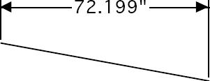
Horizontal Dimensions
A Horizontal Dimension creates a dimension with horizontal leader lines and vertical extension lines. Horizontal and vertical for the drawing are defined by the x and y axis of the construction plane. To create a horizontal dimension, select the object you desire to dimension and locate the position corresponding to the lower right text location. Modifying the object will automatically regenerate the dimension.
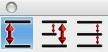
There are three types of horizontal dimensions available, from the sub-tool palette:

Horizontal Dimension tool
This tool creates a single horizontal dimension, from a specified start point to a specified endpoint. Using the Horizontal Dimension tool
- Click the mouse for the dimension start.
- Click the mouse for the dimension end.

Horizontal Baseline tool
This tool creates a horizontal series of dimensions with one baseline dimension of the entire distance. Using the Horizontal Baseline tool
- Click the mouse for the dimension start.
- Click to set a series of horizontal dimensions.
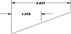
Click the mouse for the dimension end.

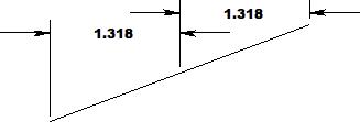
Horizontal Chain tool
This tool creates a horizontal series of individual dimensions over a specified distance. Using the Horizontal Chain tool
- Click the mouse for the dimension start.
- Click the mouse for the dimension end.
- Continue to define individual dimensions along a surface.
Vertical Dimensions
A Vertical Dimension creates a dimension with vertical leader lines and horizontal extension lines.
Horizontal and vertical for the drawing are defined by the x and y axis of the construction plane.
There are three types of vertical dimensions available, from the sub-tool palette:

Vertical Dimension tool
This tool creates a single vertical dimension, from a specified start point to a specified endpoint. Using the Vertical Dimension tool
- Click the mouse for the dimension start.
- Click the mouse for the dimension end.


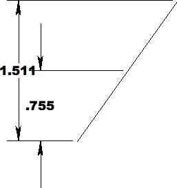
Vertical Baseline tool
This tool creates a vertical series of dimensions with one baseline dimension of the entire distance. Using the Vertical Baseline tool
- Click the mouse for the dimension start.
- Click to set a series of vertical dimensions.
Click the mouse for the dimension end.

Vertical Chain tool
This tool creates a vertical series of individual dimensions over a specified distance.
Using the Vertical Chain tool
- Click the mouse for the dimension start.
- Click the mouse for the dimension end.
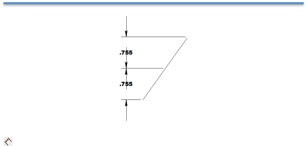
Continue to define individual dimensions along a surface.
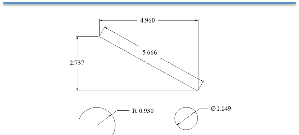
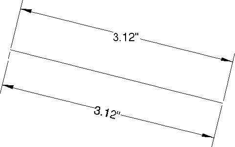
Parallel Dimension
A Parallel Dimension creates a dimension with parallel leader lines and perpendicular extension lines relative to the object selected.
Using the Parallel Dimension tool
- Click the mouse for the dimension start.
- Click the mouse for the dimension end.
Ordinate Dimensions
The Ordinate Dimension tool dimensions distances relative to a base point. Two options are provided for creating horizontal and vertical ordinate dimensions.

Using the Horizontal Ordinate Dimension tool
- Click the mouse for the ordinate base point.
- Click the mouse for additional ordinate dimensions.
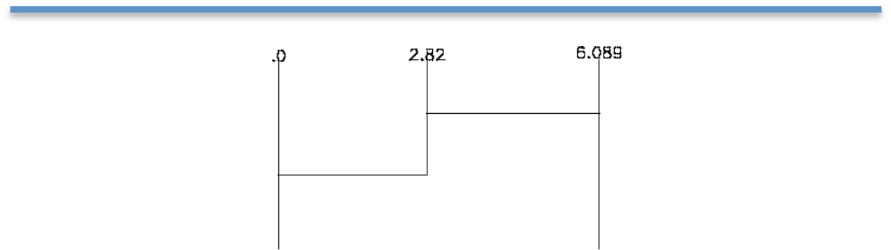
Select a new tool to stop creating ordinate dimensions

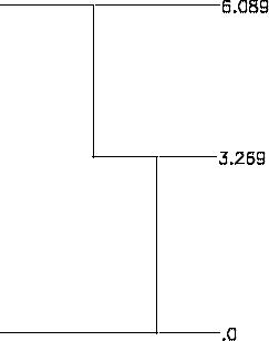
Using the Vertical Ordinate Dimension tool
- Click the mouse for the ordinate base point.
- Click the mouse for additional ordinate dimensions.
- Select a new tool to stop creating ordinate dimensions.
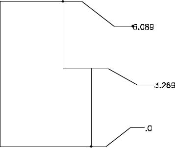
Modifying Ordinate Dimensions
- Select the Arrow tool to modify an ordinate dimension.
- Box select the ordinate dimension near the text location.
- Drag the text label (creating an elbow) to the new location.
Radial Dimensions
A Radial Dimension measures the radius of a circle or arc and creates a dimension with either arrows inside or arrows outside. The resulting dimension is associative to the arc or circle.
Using the Radial Dimension tool
- Select an arc or circle.
- Click the mouse for the dimension end.
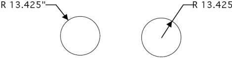
Arrow OutsideArrow Inside
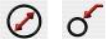
Diametrical Dimensions
A Diametrical Dimension measures the diameter of a circle. To create a diametrical dimension, select a circle and indicate the location of the text. A diametrical dimension is linked to the original object such that any modifications to the object will automatically regenerate the dimension.
Using the Diameter Dimension tool
- Select an arc or circle.
- Click the mouse for the dimension end.
Arrow OutsideArrow Inside

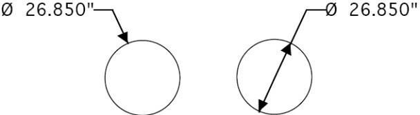
Angular Dimensions
Angular Dimensions measure the angle between any two lines.
Using the Angular Dimension tool
- Select first line.
- Select second line.
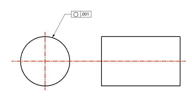
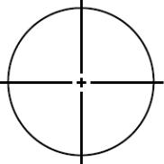
Center Mark Dimension
The Center Mark Dimension will locate and mark the center of a circle or entity. There are three tools available for finding a CenterPoint.

Center Mark Circle
To create a center mark simply select the desired circle. Note that if you change the circle by modifying the radius or moving its position the center mark will automatically regenerate because of the associativity that is created.
Using the Center Mark Dimension tool
- Select circle.

Centerline
The Centerline tool determines the center between two user-defined points. The Axis overlap text field, on the Prompt window, controls how far the line extends beyond each point.
Using the Centerline tool
- Click to set the first point along which the centerline will follow.
- Click the next point to draw the line.

Centerline Bisector
The Centerline Bisector tool references two lines. The bisector of the of the two lines defines the center line dimension.
The image part with re lationship ID r Id474 wa s not f ound in the file .
Using the Centerline Bisector tool
- Click two lines (or circles) between which you want a centerline drawn.

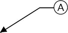
Balloon and Callout Dimensions
A Balloon Dimension creates a label with a surrounding graphic that may be a circle, square or triangle. A callout dimension contains no surrounding graphics. There are eight balloon dimensions and one callout dimension.
Using the Balloon Dimension tool
- Select balloon type.
- Click location for balloon arrow to point at.
- Click location for text extension line to start at.
- Use the Data Entry Fields to modify the text or width of the enclosing graphic.
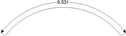
Length Dimension

The Length Dimension creates an associative dimension to the length of a curve.
Using the Length Dimension tool
- Click dimension start location.
- Click dimension end location.
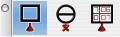
 Area Dimension
To access the Area Dimension tool tear out the dimension tool palette and select the area dimension tool icon. The area dimension works with collections of closed curves or polygons. There are two options accessed through the data entry window.
-
Leader Line Dimension
-
Text at Centroid
Using the Area Dimension tool
Select Pick Leader Line Dimension.
And now select the collection of curves or polygon. Then select the arrow location and text location.
Now change the area method to text at centroid. And select the polygon.
The area dimension is associative to the curves originally selected. Modifying a curve will update the area dimension.
The Area dimension also work with a collection of curves used in a constrained system. In this case, updating any dimension value, will update the area dimension
 Geometric Dimension and Tolerance
(Available in TurboCAD Mac Pro)
Geometric dimensioning and tolerancing (GD&T) are a language used on mechanical engineering drawings composed of symbols that are used to efficiently and accurately communicate geometry requirements for associated features on components and assemblies.

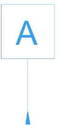
Datum Feature tool
A Datum Feature is the actual component feature used to establish a datum.

Datum Target tool

A Datum Target is a specified point, line or area on a part that is used to establish the datum reference plane for manufacturing and inspection operation
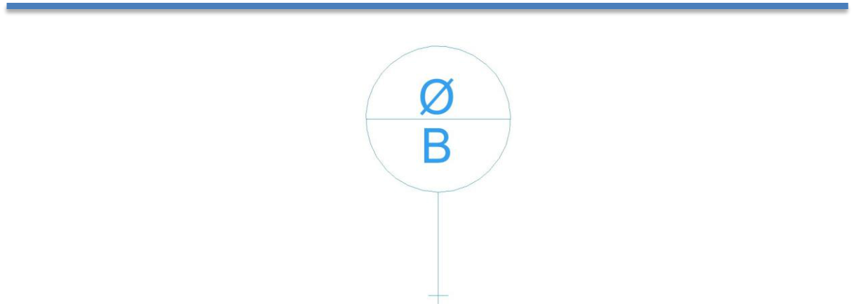
Feature Control Frame tool
A Feature Control Frame is a rectangular box containing the geometric characteristics symbol, and the form, runout or location tolerance. If necessary, datum references and modifiers applicable to the feature or the datums are also contained in the box.
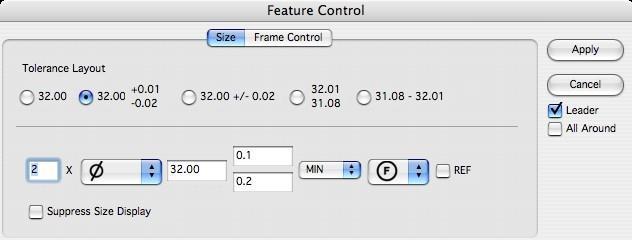
Size
The Size tab page is used to define the basic dimension and tolerance values along with other optional modifiers. This size specification is also known as the Limits of Size. Selecting one of the five Tolerance Layout radio buttons controls the tolerance style. The dialog controls are repositioned to match the current Tolerance Layout selection.
•
•
•
Tolerance Layout – specifies the tolerance configuration.
Number of Places – the X is used along with a value to indicate the number of times a dimension or
feature is repeated on the drawing.
Leader – adds an arrowhead and leader line.
- All Around – indicating that a tolerance applies to surfaces all around the part. Adds a circle about the
- leader lines.

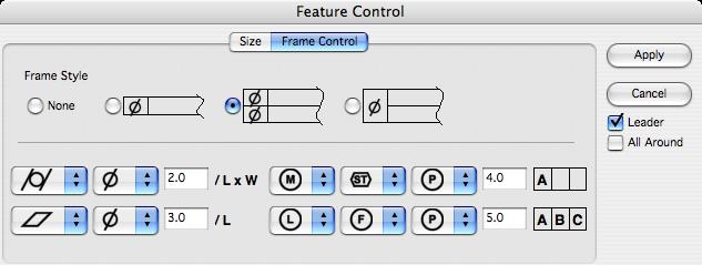
Frame Control Page
The Frame Control tab page is used to define the geometric relationships for the dimensioned feature.
Selecting one of the four Frame Style radio buttons controls the layout for the feature control frames.
The supported frame styles are None, Single, Dual, and Composite. The dialog controls are repositioned to match the current Tolerance Layout selection. The Feature Control tab also uses 2 additional support dialogs; Unit Basis and Datum Reference. The Unit Basis dialog is displayed by clicking on the region of the dialog box. The Datum Reference dialog is displayed by clicking on the (ABC) region of the dialog box.
•
•
Frame Style – indicates the type of frame for the feature control.
****/L – displays the Unit Basis dialog.

Displays the Datum Reference dialog.
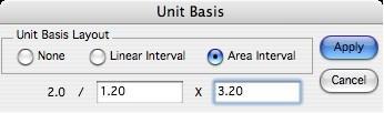
Unit Basis Dialog
When appropriate for a feature, the Unit Basis Dialog defines the unit basis interval (subregion) over which the tolerance value is applied. The unit basis interval can be one of “None", "Linear”, and “Area”. A “None” interval (the default) applies the allowed tolerance over the entire feature. A “Linear”
interval applies the allowed tolerance per any linear sub-length along the feature. An “Area” interval applies the allowed tolerance per any rectangular sub-area of the feature. If a linear interval is defined, the Feature Control tab page will display a /L indicator. If an area interval is defined, the Feature Control tab page will display a /LxW indicator.
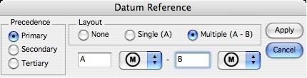
Datum Reference Dialog
When appropriate for a feature, the Datum Reference Dialog associates existing datum planes (local coordinate origin) with the dimension. A maximum of 3 datums (Primary, Secondary, Tertiary) can be associated with a feature control frame. A datum must be fully defined in order to add another datum reference. A datum consists of a datum letter (any combination of the letters A-H, J-N, P, R-Z and an optional modifier symbol. The letters I, O, and Q are not allowed. For a multiple datum, a second datum letter and optional modifier symbol follow a dash
| Chapter 24: Dimension | 245 |
|---|---|

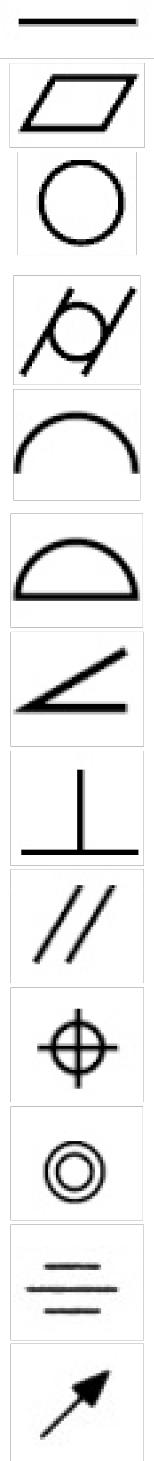
| Description | Geometry | Notes | |
|---|---|---|---|
| Straightness | Form | A condition where an element of a surface | |
| or an axis is a straight line. | |||
| Flatness | Form | A condition of a surface having all | |
| elements in one plane. | |||
| Roundness | Form | Describes the condition on a surface of | |
| revolution (cylinder, cone, sphere) where | |||
| all points of the surface are intersected by | |||
| any plane. | |||
| Cylindricity | Form | Describes a condition of a surface of | |
| revolution in which all points of a surface | |||
| are equidistant from a common axis. | |||
| Profile of a Line | Profile | The condition permitting a uniform | |
| amount of profile variation, either | |||
| unilaterally or bilaterally, along a line | |||
| element of a feature. | |||
| Profile of a Surface | Profile | The condition permitting a uniform | |
| amount of profile variation, ether | |||
| unilaterally or bilaterally, on a surface. | |||
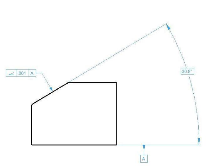
| Angularity | Orientation | The condition of a surface, axis or | |
| centerplane, which is at a specified angle | |||
| from a datum plane or axis. | |||
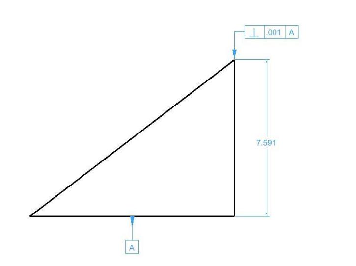
| Perpendicularity | Orientation | The condition of a surface, axis or line, | |
| which is 90-degrees from a datum plane | |||
| or a datum axis. | |||
| Parallelism | Orientation | The condition of a surface, line or axis, | |
| which is equidistant at all points from a | |||
| datum plane or axis. | |||
| Position Tolerance | Location | Defines a zone within which the axis or | |
| center plane of a feature is permitted to | |||
| vary from true position. | |||
| Concentricity | Location | Describes a condition in which two or | |
| more features, in any combination, have a | |||
| common axis. | |||
| Symmetry | Location | A condition in which a feature (or | |
| features) is symmetrically disposed about | |||
| the center plane of a datum feature. | |||
| Runout | Runout | The composite deviation from the desired | |
| form of a part surface of revolution | |||
| through on full rotation (360 deg) of the | |||
| part on a datum axis. |
| Total Runout | Runout | The simultaneous composite control of all | |
|---|---|---|---|
| elements of a surface at all circular and | |||
| profile measuring positions as the part is | |||
| rotated through 360. | |||
| Maximum Material | Modifier | A condition of a part feature wherein it | |
| Condition (MMC) | contains the maximum amount of material | ||
| within the stated limits of size. | |||
| Least Material | Modifier | A condition of a part feature of size | |
| Condition (LMC) | wherein it contains the least (minimum) | ||
| amount of material; examples, largest hole | |||
| size and smallest shaft size. It is opposite | |||
| to maximum material condition. | |||
| Projected Tolerance | Modifier | Applies to a hole in which a pin, stud, | |
| Zone | screw, etc., is to be inserted. It controls | ||
| the perpendicularity of the hole to the | |||
| extent of the projection from the hole and | |||
| as it relates to the mating part clearance. | |||
| Tangent Plane | Modifier | Indicating a tangent plane is shown. The | |
| symbol is placed in the feature control | |||
| frame following the stated tolerance. | |||
| Free State | Modifier | A term used to describe the distortion of a | |
| Variations | part after removal of forces applied during | ||
| manufacture. | |||
| Diameter | Indicates a circular feature when used on | ||
| the field of a drawing or indicates that the | |||
| tolerance is diametrical when used in a | |||
| feature control frame. | |||
| Conical Taper | Used to indicate taper for conical tapers. | ||
| This symbol is always shown with the | |||
| vertical leg to the left. | |||
| Slope | Used to indicate slope for flat tapers. This | ||
| symbol is always shown with the vertical | |||
| leg to the left. | |||
| Counter/Spotface | Used to indicate a counterbore or a | ||
| spotface. The symbol precedes the | |||
| dimension of the counterbore or spotface, | |||
| with no space. | |||
| Countersink | Used to indicate a countersink. The | ||
| symbol precedes the dimensions of the | |||
| countersink with no space. | |||
| Depth/Deep | Used to indicate that a dimension applies | ||
| to the depth of a feature. This symbol | |||
| precedes the depth value with no space in | |||
| between. | |||
| Square | Used to indicate that a single dimension | ||
| applies to a square shape. The symbol | |||
| precedes the dimension with no space | |||
| between. |

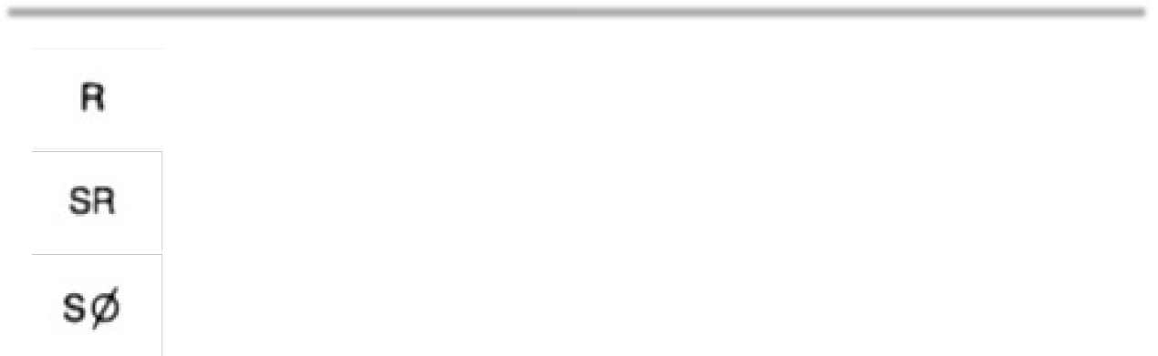
| Radius | Creates a zone defined by two arcs (the | ||||
| minimum and maximum radii). The part | |||||
| surface must lie within this zone. | |||||
| Spherical Radius | Precedes the value of a dimension or | ||||
| tolerance. | |||||
| Spherical Diameter | Precedes the tolerance value where the | ||||
| specified tolerance value represents | |||||
| spherical zone. The symbol for spherical | |||||
| diameter precedes the size dimension of | |||||
| the feature and the positional tolerance | |||||
| value, to indicate a spherical tolerance | |||||
| zone. | |||||
| Controlled Radius | Creates a tolerance zone defined by two | ||||
| arcs (the minimum and maximum radii) | |||||
| that are tangent to the adjacent surfaces. | |||||
| Statistical Tolerance | Assign tolerances to related components | ||||
| of an assembly on the basis of sound | |||||
| statistics. | |||||
GD&T Examples
Below are several examples of uses of GD&T dimension tools relative to geometry.
Angularity
Perpendicularity
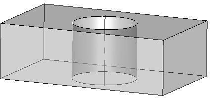
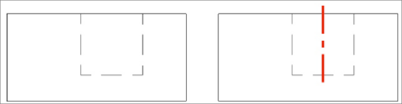
Cylindricity
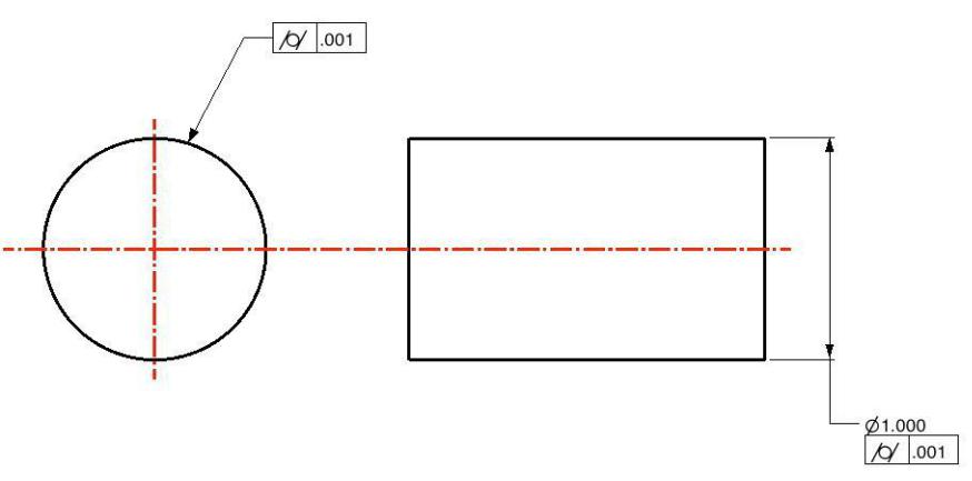
Circularity