Printing and Paper Space
Printing and Paper Space
This section covers how to prepare your drawing for printing and all the printing options.
Paper Space
Paper Space is essentially the printing mode. In paper space, you can define areas and views you want to print.
Paper Space Mode
Menu: File / Paper Space View Frame Setup / Paper Space Mode
Toolbox Icon:
Makes it possible to print multiple views of the same drawing in a single print job. Options such as perspective, shading, light source, focal point, view settings, and zoom can be set for each separate view created in the Paper Space.
Choose the Paper Space Mode command, which puts you into Paper Space Mode with the most recently-defined layout. However, if no layouts have been created yet, the command first displays the Paperspace Configuration window (see “Paper Space Configuration” on page 65) It also automatically creates a view frame to fit the page, with the view frame scale set to 100%. This view frame can be scaled and more customized view frames can be added using the Create View Frame command, available on the Paper Space window or the View Frame menu which appears once Paper Space Mode is enabled.
NOTE: To exit Paper Space mode, select File / Paper Space or click the Paper Space icon to deselect it.
The Paper Space Bar appears at the top right of the screen:
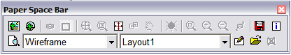
There are several options available in the window which can be set for each view frame.
Create View Frame: Create a printable view window for which you set the placement, size, and view options.
Select the View Settings and Drawing Display
Size for the View Frame. If you don’t want to use a standard view, you can select Custom and define your own view angles. Now move the cursor to the location in the Paper Space at which you want to place the first corner of the View Frame. Press and hold the mouse button. Drag the mouse until the rubber-band preview is the size you want the View Frame. Release the mouse button. The rubber band preview is replaced with a View Frame border with your drawing inside.
The View Frames can also be drawn using the Point Polar and Point Relative commands.
NOTE: View frames can be changed by using the Info Box.

Pick an Entity as View Frame: Uses simple 2D entities, that have been drawn while in Paper Space Mode, as view frames. Just draw the entity, click on this option and then click on the entity you just drew. That entity is used as a view frame for the drawing.

Change View Setting:
Provides several different view options for an individual View Frame can be set using this command.
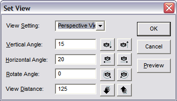
- View Setting: Determines which view of the drawing is shown in the View Frame. The views listed are the same as those in the Projection list-box in the View toolbox.
-
Angles and View Distance: Set the vertical or horizontal angle of the drawing, rotate the drawing angle, or set the view distance.
-
Preview: Previews the view setting changes made to the current View Frame of the drawing.

Draw Outline Box:
Displays or hides an outline border around the selectedView Frame. This command works as a toggle, showing or hiding the border.

Fit to View Frame: Centers the drawing in the View Frame, with all objects visible.

Center on View Frame: To center the drawing in the View Frame without changing the zoom factor, use this command instead of Fit to View Frame.

Fit Drawing to Paper: Resizes the view frames so that all view frames will fit within the paper space at the largest possible size.
 Set Focal Point: Drags the drawing in the View Frame by its center point.

Pan Drawing: Slides the drawing across the View Frame using a reference point and the new location for that point.

Light Source & Layer Settings:
Sets these options for the current View Frame.
Light Source Option

Section Zoom:
This command uses a zoom window to zoom in on a specific area of the drawing.
Zoom In: Zooms in at increments preset by the program.

Zoom Out: Zooms out at increments preset by the program.

Change Zoom Factor: Changes the zoom factor of the currently selected view frame interactively. Click on this option and move the cursor into the Paper Space area. Press and hold the mouse button. Move the cursor up to increase the zoom factor or down to decrease the zoom factor. When the desired appearance is achieved, release the mouse button.

Save Current Layout as Template: Saves the current Paper Space Template, including all View Frames and the options set for each.
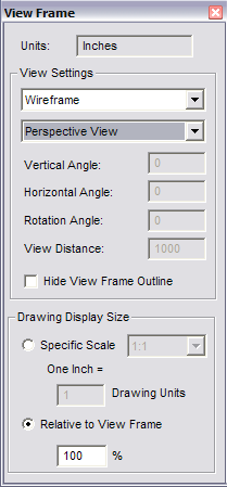
 Info Box:
When a view frame is selected, clicking this button opens the Info Box which contains information about the view frame such as view settings, the view frame’s dimensions, and the drawing display size. Most of this information can be changed in the Info Box.
Info Box:
When a view frame is selected, clicking this button opens the Info Box which contains information about the view frame such as view settings, the view frame’s dimensions, and the drawing display size. Most of this information can be changed in the Info Box.

Preview:
Shows a preview of how the printed Paper Space will look including shading and hidden line removal.
NOTE: To see the page layout including margins, use the Print Preview command on the Toolbar.
Display Method: Designates a display method for the current view frame. The changes to the Display Method will only be seen with the Preview command in the Paper Space window.
Paper Space Layout: Select a different Paper Space template in which to display the drawing.

Edit Layout:
Opens the
Paper Space Template
window so you can change the paper size and margins for the current template.

Add a New Layout:
Opens the
Paper Space Template
window so that a template can be added to the Paper Space Layout list box.

Delete Current Layout:
Deletes the currently selected template in the Paper Space Layout list box.
Paper Space Configuration
Menu: File / Paper Space View Frame Setup / Paper Space Configuration
(Available only when not in Paper Space mode.)
Sets up the area to be used for the Paper Space Mode. This command should be used to ensure that the Paper Space that is about to be created will print correctly when the time comes.
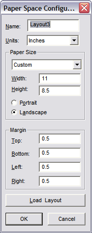
Name: The name of the currently selected Paper Space Template.
Units: The unit of measurement used for specifying the margins for the Paper Space Configuration. Notice that the Height and Width values also automatically convert to the selected unit of measurement.
Paper Size: The paper size that your printer uses.
Width and Height: Measurements of the paper size selected in the units of measurement that are currently selected in the Units list box.
Portrait and Landscape: Vertical or horizontal paper orientation.
Margin: Set the margins from the top, bottom, left, and right.
Load Layout: Opens the Paper Space Template window which allows the selection of a previously saved Paper Space Template.
OK: Saves the changes you have made and opens Paper Space Mode.
Cancel: Disregards the changes you have made and returns you to your drawing.
Load Paper Space Template
Menu: File / Paper Space View Frame Setup / Load Paper Space Template
Load or change a Paper Space Template.
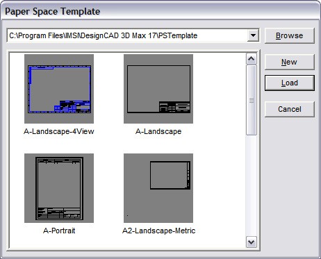
Select the template you wish to use and click
Load.
To use a blank template, click New. Your drawing is arranged in the Paper Space according to the template you selected.
To change the template, follow the same steps. Your drawing is rearranged in the Paper Space according to the new template.
Automatic Rendering
Menu: File / Paper Space View Frame Setup / Automatic Rendering
A toggle that determines whether or not View Frames that have been set up to appear with hidden line removal or shading in Paper Space Mode will be rendered when the Paper Space Template is opened.
If Automatic Rendering is disabled, the drawing will initially display faster in Paper Space Mode because the view frames will open in wireframe, but the view frames that have hidden line removal or shading turned on, will still be previewed and printed that way.
Paper Space Layout
These commands are used to save your paper spaces as templates.
NOTE: These commands are only available when DesignCAD is in Paper Space Mode.
Current Layout Configuration
Menu: Layout / Current Layout Configuration (within Paper Space Mode)
Opens the Configuration, which you can use to modify the current paper space.
Delete Current Layout
Menu: Layout / Delete Current Layout (within Paper Space Mode)
Deletes the current paper space layout.
Save Current Layout as Template
Menu: Layout / Save Current Layout as Template (within Paper Space Mode)
Saves the current Paper Space Template, including all the View Frames and the options set for each.
While in Paper Space Mode, choose the Save Current Layout as Template command. The command can also be selected by clicking on the Save Current Layout as Template icon in the Paper Space Mode window. Specify the name of the template and the location where you want to save it and click OK. The Paper Space Template is saved. Saving the template saves every View Frame’s location and size, along with the specific options Templates you create and save can be loaded using the Load Paper Space Template command.
Menu: File / Print
Shortcut Key: Ctrl+P
Toolbox Icon: Fast Print for the entire drawing
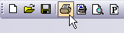
Fast Print for the current view
NOTE: By default, clicking the Print icon automatically sends the current view to the currently selected printer and prints it at the largest size possible on a single sheet of paper. You can change this by selecting Options / Options, opening the General tab, and unchecking Enable Direct Print from Toolbar the most recent driver from the manufacturer.
**
Outputs your drawing to a printer or plotter. The drawing is printed at the view and perspective of the current view.
DesignCAD offers many options, but you don’t have to use them all. If you want to print your drawing on a single sheet of paper and the maximum size, just select Fit to Paper and click Print. The other options can be used to print
to scale, rotate the drawing 90 degrees, set the margins, and so forth.
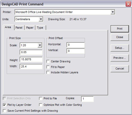
Printer: Select the printer for the pending print job from the list of available printers by clicking on the arrow to the right of the Printer field. If you would like to see the properties for the selected printer, click the Setup button.
NOTE: If you do not see the printer you would like to use for the print job in the list of available printers, make sure the printer is installed correctly in Windows. If you have problems, consult your Windows documentation and your printer manual. Make sure you have not only the correct driver installed, but also that it is
Units: The unit of measurement for the paper on the printer. Don’t confuse this item with Drawing Units. Drawing Units are the units of measurement of the drawing itself, not the printer.
Drawing Size: The size of the box that would just fit around the current view if the drawing were projected onto a flat surface. The size is given in DesignCAD Drawing Units.
Area: The size of your printed drawing.
Scale: A ratio that represents the number of paper units that will be used to print one Drawing Unit. You can choose from several standard scales, or create your own. Suppose, for example, that you are printing the front view of a 2x2 box, and you have chosen “inches” for the paper units. If you set Scale to 1.0, then one inch of paper will be used for each Drawing Unit and the box will be printed out at two inches by two inches on the paper. If you set Scale to 2.0, then two inches of paper will be used to print each Drawing Unit, and the box will be printed at four inches by four inches. With a Scale of 0.25, the box will be printed at 0.5 inches by 0.5 inches. See “Printing to Scale” on page 5.
Height and Width: The height and width of the printed drawing on the paper if printed at the current scale. If you are printing multiple panels, this number is the total height or width of the drawing across all panels.
Print Offset: How far the drawing will be printed from the left (Horizontal) or top (Vertical) edge of the paper for the print job. Positive values move the position of the printed image to the right or down.
Center Drawing: Centers the drawing on the paper.
Fit to Paper: Outputs the drawing on a single page in the largest possible size. If this option is selected, the Scale, Height, and Width cannot be changed.
Include Hidden Layers: Takes the entire drawing (including hidden layers and unselected objects) into consideration when determining the scale and center position of the printed drawing. This is an easy way to print transparencies.
Print Selection Only: Only the currently selected object or objects will be printed. If no objects are selected, this box is not available.
Print by Layer Order: Sends the drawing to a plotter one layer at a time.
Print to File: Sends the print information to a file rather than to the actual printer. This is convenient if you need to print or plot your drawing at another location. It can also be used to transfer the drawing image to other applications.
Optimize Plot with Color Sorting: Sends the drawing to a plotter one color at a time.
NOTE: The status of the Optimize Plot with Color Sorting option is not saved in the drawing file, thus you will need to reselect it when you get ready to plot the drawing in subsequent drawing sessions.
Copies: The number of copies to be printed.
Print: Starts the printing process.
Close: Saves the changes you have made to the options in the Print window closes the Print window and returns you to your drawing.
Setup: Displays the page setup options for the currently selected printer.
Preview: Displays the Print Preview screen, which shows exactly how your drawing will look
NOTE: The status of the Print by Layer Order option is not saved in the drawing file, thus you will need to reselect it when you get ready to plot the drawing in subsequent drawing sessions.
Save Current Print Settings with Drawing: Saves the options set in the Print window so that the drawing can be printed again without resetting the options. This option also makes it possible to print the drawing with the same options using direct print from the Toolbar on paper.
Cancel: Disregards any changes you have made to the Print window and closes the Print window.
Panel Options
This group of options gives you information about how multiple panels will be handled. If a drawing is scaled too large to fit on a single page, DesignCAD will print the portions of the drawing on separate sheets of paper which can then be assembled. For example, if a drawing is printed in four panels, then each panel would contain one-quarter of the drawing. This makes it possible to print drawings at a large scale with standard paper sizes.
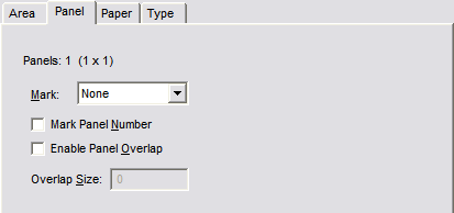
Panels: 1 (1x1): The total number of panels to be printed, and how many across by how many down.
Mark: How to mark the boundaries of the individual panels.
- None: No panel marking is done.
- Corner Mark: A registration mark is printed at each of the corners of the panels. This makes it easy to align the panels after printing.
- Outline Box: Boxes are drawn around each panel to indicate margin locations. Each panel can be trimmed to the edge of these boxes so that when the panels are assembled edge-to-edge, the alignment of the panels will be correct. This way no paper overlap will interfere with the image.
Mark Panel Number: Each panel will be numbered. This is useful in arranging the panels correctly when assembling the finished printout of the drawing.
Enable Panel Overlap: Eases the assembly of paneled drawings. This option creates a specified image overlap between the panels. This eliminates the need for precise panel trimming before assembly.
Overlap Size: The amount of overlap DesignCAD prints on a panel when the Panel Overlap option is used. The Overlap Size is applied to each side of every panel that overlaps another panel.
Paper Options
This group of options lets you choose your paper orientation and margins.
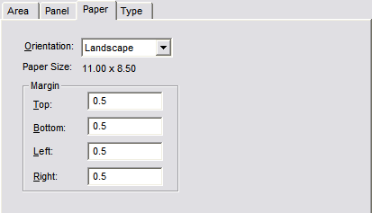
Orientation: Portrait is a vertical orientation, Landscape is horizontal. This can also be set via the Setup button on the Print window.
Paper Size: The currently selected paper size.
Margin: The size of the page margins, measured from the top, bottom, left, and right.
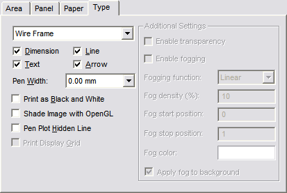
Type Options
These options let you print your drawing in several forms:
For the differences between wireframe, quick shade, smooth shade, and hide.
Dimension: Prints dimensions in the drawing.
Text: Prints text regardless of whether it is on the near side, inside, or far side of a shaded solid. This option also shows text in views in which the hidden lines have been removed.
Line: Prints lines regardless of whether they are on the near side, inside, or far side of a shaded solid. This option also shows all lines in views that have the hidden lines removed.
Arrow: This option print arrows regardless of whether they are on the near side, inside, or far side of a shaded solid. This option also shows all arrows in views that have the hidden lines removed.
Pen Width: This option can be used to increase the print width of the lines in a drawing. With some high-resolution printers, the zero width lines are difficult to see or do not print as complete lines. This option alleviates some problems with printing zero width lines.
Print as Black and White: Some colors print very lightly on black and white printers. When you are not using a color printer to print your color drawings, check this option to print all drawing entities as if they were black.
Shade Image with OpenGL: Uses OpenGL shading to print the drawing.
Pen Plot Hidden Line: Send the print/plot information necessary for a hidden line removal to a pen plotter.
Print Display Grid: If you have used a display grid in your drawing and the drawing is in 2D Mode, this option tells DesignCAD whether or not to print the Display Grid with the drawing.
Enable Transparency: Show transparencies when a drawing contains objects that have been assigned materials that have transparent qualities.
Enable Fogging: Add a fog effect to the printed drawing.
Fogging Function: Linear produces proportionally more the fog, the “deeper” into the drawing you go. Exp produces a less dense fog than Linear. Exp2 also produces a less dense fog than Linear, following a different function than Exp.
Fog Density (%): The maximum fog density.
Fog Start Position: The point in the drawing where the fog is at its minimum. This value is a scale factor based on the depth of the drawing from the front to the back at the current view settings. A value of 0 starts the fog at the very front of the drawing. A value of -1 starts the fog one drawing-depth in front of the drawing’s front. A value of 0.5 starts the fog in the middle of the drawing.
NOTE: This position and scaling will vary depending on the size of the drawing, the viewing angle, and distance settings.
Fog Stop Position: The point in the drawing where the fog reaches its maximum thickness. Like the Fog Start Position, this value is a scale factor based on the depth of the current view of the drawing.
Fog Color: The desired base color for the fog. To select the color, click the color box and select a color from the palette.
Apply Fog to Background: The entire drawing background becomes the same color as the fog.
Batch Print
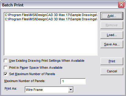
Menu: File / Batch Print
Prints several specified files at one time.
Add: Select the files to be added to a batch.
Remove: Remove files from a batch.
Load: This option is used to load a batch (.dbp) file that has been created and saved previously.
Save As: Save a batch (.dbp) file under a specified filename.
Use Existing Drawing Print Settings When Available: Use existing print settings, if the current print settings have been saved with the drawing by enabling the Save Current Print Settings option in the Print window.
Print in Paper Space When Available: Prints the drawing in Paper Space Mode, if a Paper Space has been configured for the drawing.
Set Maximum Number of Panels: Makes it possible to constrain all of the files for the batch print to a specific number of panels.
Print As: Specifies whether the batch will be printed as Wireframe, Shading, Hide, or Hide (Pen Plotter).
Print: Sends the batch to the specified printer.
Close: Closes the window and returns to DesignCAD without printing or retaining any changes.
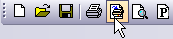
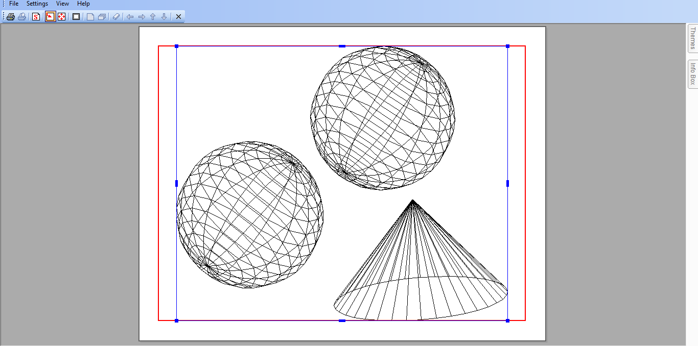
Print Preview
Menu: File / Print Preview
Toolbox Icon:
Shows exactly how your drawing is going to look on paper. There are also several options that can be adjusted from the Print Preview window.
Print: Prints the drawing.
Change Printer Setting: Brings up the Print Command window, making it possible to change the settings for the print job. Pressing Enter will print the drawing. To get back to the Print Preview screen, click the Close button.
Center Drawing: If the drawing fits on a single piece of paper, this command will center the drawing on the paper. If it is a multi-paneled drawing, this command centers the drawing so that there is the same amount of white space above and below the drawing and the same amount of white space on each side of the drawing.
Fit to Paper: Outputs the drawing on a single piece of paper on the largest scale possible.
Print Region: Lets you define a region of the drawing to be printed. Move the mouse to one corner of the region. Hold down the left button and drag a rectangle around the region. Release the mouse button at the opposite corner.
Show Single Panel: Shows only the currently selected panel, enlarged to fit the screen.
Show All Panels: Shows all panels of the drawing on the screen.
Mark/Unmark Skipped Panel: Works as a toggle to select or deselect individual panels and determine whether or not they will be printed, Panels that will not be printed are grayed out.
Left Page or Right Page: In a multi-paneled view, select the panel to the left or right of the currently selected panel. In single-paneled view, changes the view so that the panel being viewed is the one to the left or right of the panel currently being viewed.
Up Page or Down Page: In a multi-paneled view, selects the panel directly above or below the currently selected panel. In a single-paneled view, changes the view so that the panel being viewed is the one directly above or below the panel currently being viewed.
Close Print Preview: Returns to the Print window.
When the entire drawing is shown, either on a single sheet or in panels, there are blue scaling and moving nodes around the drawing. The small blue box at each corner is a scaling node and can be used to scale the drawing. To scale the drawing, click on one of the scaling nodes and hold down the mouse button. Move the mouse until the drawing is scaled to the desired size, then release the mouse button. The small blue box on the top, bottom and each side of the drawing is a moving node. To move the drawing, simply click and hold on one of the moving nodes or one of the blue lines around the drawing. Use the mouse to move the drawing to the desired location, then release the mouse button. If you move the drawing past the edge of the pages shown, DesignCAD automatically adds pages as needed for the print job.
Page Setup
Menu: File / Page Setup
Used to change some of the DesignCAD printer options. This window can also be accessed by clicking the Setup button in the Print window.
Size: Select the paper size for your drawing from a list of standard sizes.
Source: Select the paper source from a list of standard printer paper sources.
Orientation: Portrait is a vertical orientation, Landscape is horizontal.
Margins: The size of the page margins, measured
from the top, bottom, left, and right.
Printer: Brings up the window for selecting the
printer for the pending print job.
OK: Saves the changes you have made and returns you to your drawing.
Cancel: Disregards the changes you have made and returns you to your drawing.