Sheet Metal


Sheet Metal Tools Overview
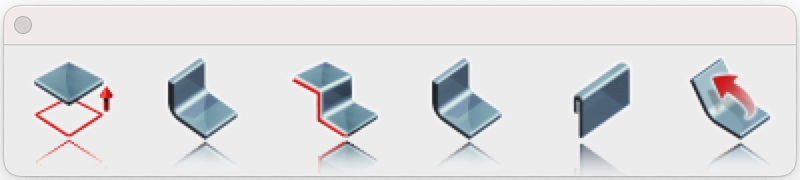
The Sheet Metal tools in application provide a powerful suite of features for designing and manipulating sheet metal parts with precision. These tools enable users to create complex geometries—such as tabs, bends, flanges, and hems—while maintaining material integrity and adhering to sheet metal design rules like bend radius and k-factors. Whether forming structural components, enclosures, or decorative elements, these tools streamline the process from initial design to flat pattern generation.
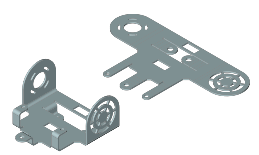
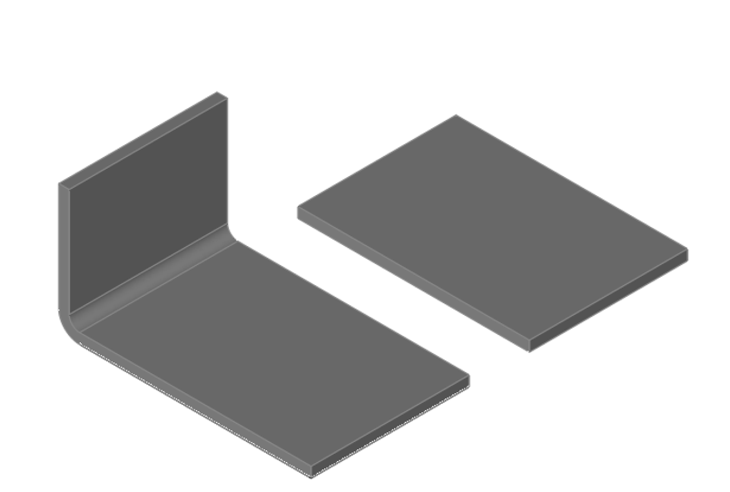
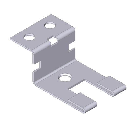
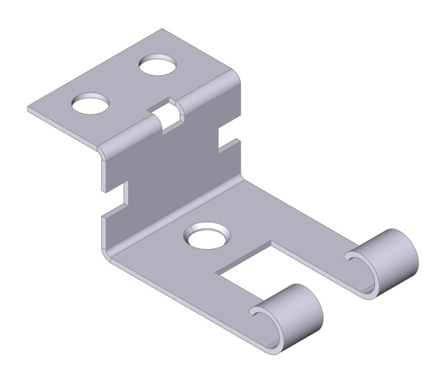
Example Sheet Metal Part
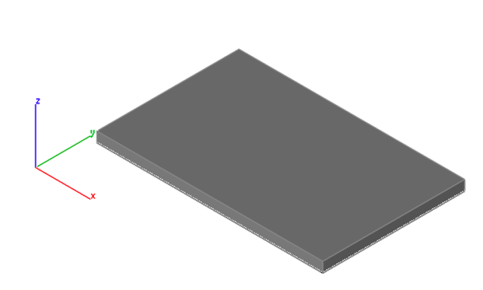
Tab
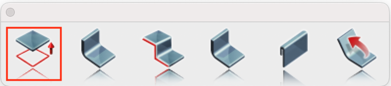
The Tab feature is a tool used to create a flat, protruding extension from a sheet metal part. A tab is typically a planar extension that remains in the same plane as the sheet metal base or flange it extends from. It can be rectangular, trapezoidal, or custom-shaped, depending on design requirements. The Tab feature often serves as the base for additional sheet metal features.
Using the Tab Tool:
- Specify the thickness.
- Select a closed profile (e.g., lines, arcs, circles, or polygons) to define the tab’s geometry.
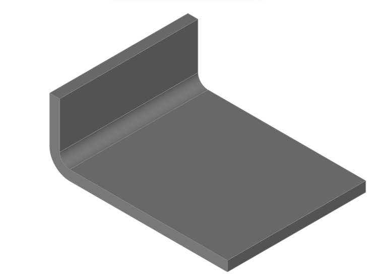
Bend
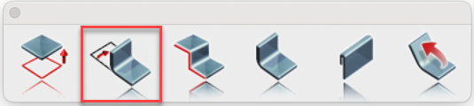
The Bend feature allows you to deform a flat sheet metal part into a curved or angled shape while preserving material integrity. This tool is essential for creating components such as brackets, enclosures, or ducts.
Using the Bend Tool:
- Select the solid to bend.
- Specify the bend angle.
- Specify the bend radius.
- Define the bend axis by selecting two points on the face to bend.
- Optional: Press the Option key to flip the bend direction.
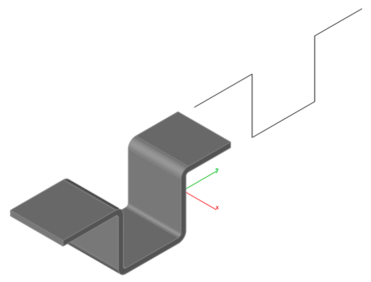
Contour Flange
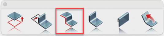
The Contour Flange feature enables you to create a sheet metal feature by extruding a sketch profile along a path defined by two points. The profile sketch can include lines, arcs, splines, or elliptical arcs. Sharp corners in the profile result in bends that conform to the bend radius specified in the sheet metal style.
Using the Contour Flange Tool:
- Select the solid to modify.
- Specify the bend angle in the data entry window.
- Specify the bend radius in the data entry window.
- Define the bend axis by selecting two points on the face to bend.
- Optional: Press the Option key to flip the flange direction (inside, outside, or middle).
Flange
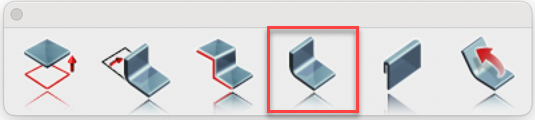
The Flange feature allows you to add a straight, planar extension or lip to an existing edge of a sheet metal part. Flanges are commonly used to strengthen, connect, or mount components. To create a flange, select an edge and define its length, angle (e.g., 90°), and bend radius, with options to adjust its position relative to the base material.
Using the Flange Tool:
- Select the solid to modify.
- Specify the bend angle in the data entry window.
- Specify the bend radius in the data entry window.
- Define the bend axis by selecting two points on the face to bend.
- Optional: Press the Option key to flip the bend direction.
Hem
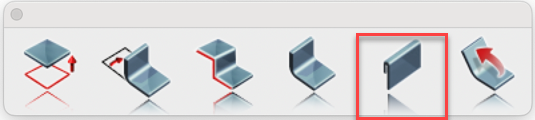
The Hem feature enables you to fold the edge of a sheet metal part back onto itself, creating a rounded or flattened lip. This enhances strength, safety, or aesthetics. To apply a hem, select an edge and specify parameters such as bend radius and length.
Using the Hem Tool:
- Specify the length.
- Specify the gap.
- Select an edge of a solid to apply the hem feature.
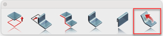
Rolled Hem
The Rolled Hem feature creates a smooth, cylindrical edge by rolling the sheet metal back onto itself in a continuous curve. This is often used for safety, strength, or decorative purposes. To use it, select an edge and define the roll diameter or radius; the software calculates the required material length and applies sheet metal rules for an accurate flat pattern. Using the Rolled Hem Tool:
- Specify the radius.
- Specify the angle.
- Specify the thickness.
- Select an edge of a solid to apply the rolled hem feature.
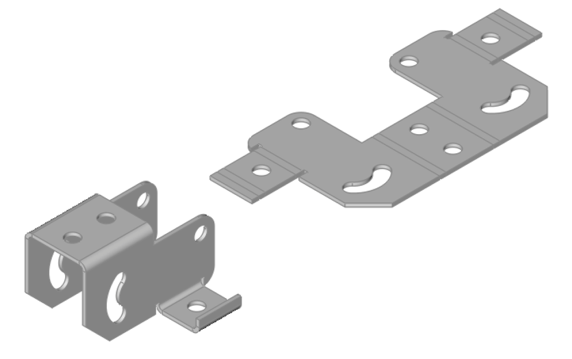
Unbend
The Unbend tool allows you to flatten a bent or curved section of a sheet metal part back to a planar state without altering the design. Select specific bends or regions, and the software reverses the deformation while preserving material properties and sheet metal rules, such as bend allowance.
Using the Unbend Tool:
- Specify the k-factor for unbending.
- Select the solid to unbend.
The K-factor is a value that represents the position of the neutral axis—the line within the sheet metal that remains unstretched and uncompressed during bending—relative to the material thickness. It is a dimensionless number, typically ranging from 0.3 to 0.5 for most materials and bend conditions, though it can vary between 0 and 1 depending on factors like material type, thickness, and bend radius. The K-factor is essential for calculating the bend allowance, which helps determine the accurate flat pattern length before bending. In practice, it ensures precise fabrication by accounting for how the material behaves during the bending process.