Part Creator


Part Creator Overview
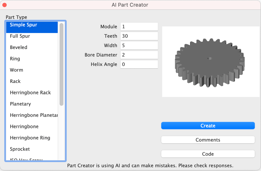
The AI Part Creator, available in Copilot Professional, enables users to generate intelligent parametric parts with ease. This feature supports the creation of over 20 types of parts, including various gears (spur, bevel, planetary, herringbone), screws, nuts, and ISO/ACME threads. The AI Part Creator can be accessed via the 'Tools' menu under 'AI Part Creator'.
Part Creator is an intelligent, AI-assisted Python scripting tool designed to create highly accurate, parametric 3D parts for engineers and designers. It simplifies the modeling of complex mechanical components with precision and flexibility. Supported part types include:
    • Spur Gears: Simple Spur, Full Spur
    • Bevel Gears: Bevel
    • Ring Gears: Ring, Herringbone Ring
    • Rack Gears: Rack, Herringbone Rack
    • Planetary Systems: Planetary, Herringbone Planetary
    • Worm Gears: Worm
    • Other Components: Sprocket, ISO Hex Screw, ISO Hex Nut
    • Threads: ACME Thread, ISO Thread
    • Structural Shapes: I-Beam, Chain
    • Pipes: Round Pipe, Square Pipe
Part Creator User Interface
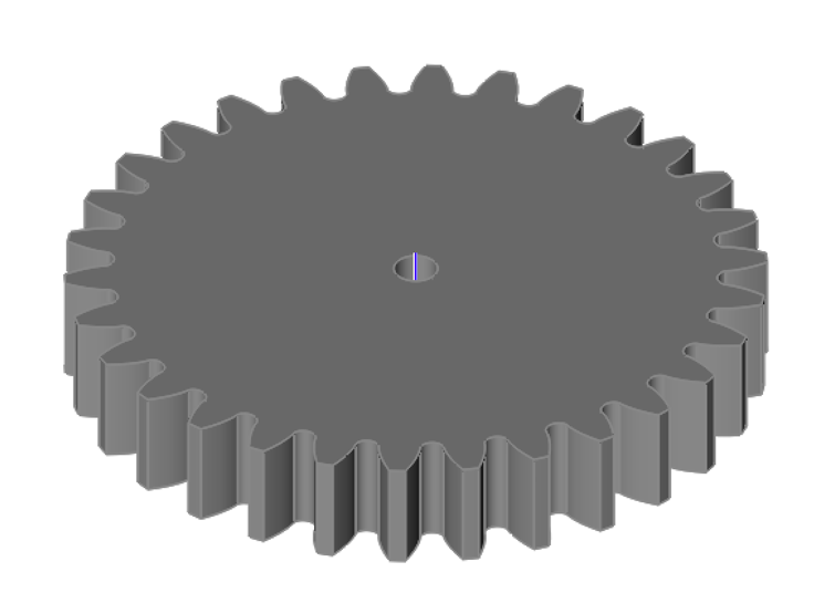
Simple Spur Gear
The Simple Spur Gear part creates a gear with the following parameters:
Module: Tooth size scaling factor sets the size of the teeth.
Number of Teeth: The number of teeth for the gear.
Width: Defines the axial thickness of the gear.
Helix Angle: Defines whether the gear has straight or helical teeth. Set to 0.0 for straight teeth.
Bore Diameter: Specifies the diameter of the central hole (bore) that fits onto a matching shaft.
Using the Simple Spur Gear Tool:
- Select the Simple Spur Gear Part type from the category list.
- Set the Module, Number of Teeth, Width, Helix angle, and bore diameter.
- Press the Create button.
The Module is a tooth size scaling factor that determines the size of the teeth on a gear. It is a fundamental metric in gear design, typically measured in millimeters, and represents the ratio of the gear's pitch diameter (the diameter of the imaginary circle where the teeth mesh) to the number of teeth. A larger module results in larger teeth, which can increase the gear's strength but may reduce precision or smoothness, while a smaller module produces finer teeth, suitable for more compact or precise applications.
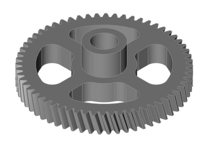
Full Spur Gear
The Full Spur Gear creates a part with a more complete set of parameters that allow for hubs and spokes.
Module: Tooth size scaling factor sets the size of the teeth.
Number of Teeth: The number of teeth for the gear.
Width: Defines the axial thickness of the gear.
Helix Angle: Straight or helix gear. Set the helix angle to 0.0 for straight teeth.
Bore Diameter: Specifies the diameter of the central hole (bore) that fits onto a matching shaft.
Hub Diameter: Sets the diameter of the hub, which adds additional stability to the gear.
Hub Length: Defines the axial length of the hub.
Recess Diameter: (Optional) Specifies the diameter of a recess around the hub.
Recess Depth: (Optional) Defines the depth of the recess.
Number of Spokes: (Optional) Indicates that the gear includes 5 spokes.
Spoke Width: (Optional) Sets the width of each spoke.
Spoke Fillet: (Optional) Specifies the fillet radius for smoothing the edges of the spokes.
Spokes Inner Diameter: (Optional) Defines the inner diameter where the spokes begin, ensuring proper alignment with the hub.
Spokes Outer Diameter: (Optional) Specifies the outer diameter where the spokes terminate.
Using the Full Spur Gear Tool:
- Select the Full Spur Gear Part type from the category list.
- Set the Module, Number of Teeth, Width, Helix angle, and bore diameter.
- Press the Create button.
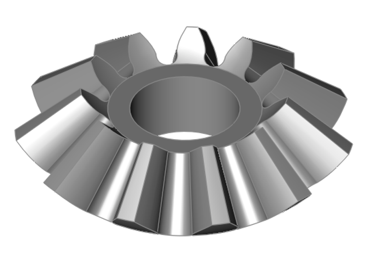
Beveled Gear
The Beveled Gear part creates a gear with the following parameters:
Module: Tooth size scaling factor sets the size of the teeth.
Number of Teeth: The number of teeth for the gear.
Face Width: Sets the thickness of the gear face along the conical surface.
Helix Angle: Straight or helix gear. Set the helix angle to 0.0 for straight teeth.
Bore Diameter: Specifies the diameter of the central hole (bore) that fits onto a matching shaft.
Using the Beveled Gear Tool:
- Select the Beveled Gear Part type from the category list.
- Set the Module, Number of Teeth, Face Width, Helix Angle, and Bore Diameter.
- Press the Create button.
Ring Gear
The Ring Gear part creates a gear with the following parameters:
Module: Tooth size scaling factor sets the size of the teeth.
Number of Teeth: The number of teeth for the gear.
Width: Defines the axial thickness of the gear.
Rim Width: Defines the width of gear’s rim.
Helix Angle: Straight or helix gear. Set the helix angle to 0.0 for straight teeth.
Using the Ring Gear Tool:
- Select the Ring Gear Part type from the category list.
- Set the Module, Number of Teeth, Width, Rim Width, and Helix Angle.
- Press the Create button.
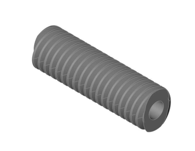
Worm Gear
The Worm Gear part creates a gear with the following parameters:
Module: Tooth size scaling factor sets the size of the teeth.
Lead Angle: Sets the angle of the worm thread’s helix relative to its axis.
Number of Threads: Specifies the total number of threads on the worm.
Length: Sets the overall length of the worm gear.
Using the Worm Gear Tool:
- Select the Worm Gear Part type from the category list.
- Set the Module, Lead Angle, Number of Threads, and Length for the worm gear.
- Press the Create button.
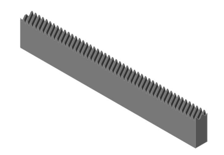
Rack Gear
The Rack Gear part creates a gear with the following parameters:
Module: Tooth size scaling factor sets the size of the teeth.
Length: Sets the overall length of the rack gear.
Width: Specifies the thickness of the rack along the direction perpendicular to the tooth profile
Height: Determines the vertical dimension of the rack's tooth profile.
Helix Angle: Defines the angle of the rack teeth relative to a line parallel to the rack's length.
Using the Rack Gear Tool:
- Select the Rack Gear Part type from the category list.
- Set the Module, Length, Width, Height, Helix Angle for the rack gear.
- Press the Create button.
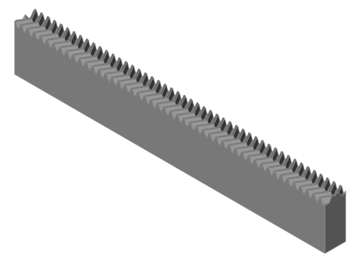
Herringbone Rack Gear
The Herringbone Rack Gear part creates a gear with the following parameters:
Module: Tooth size scaling factor sets the size of the teeth.
Length: Sets the overall length of the rack gear.
Width: Specifies the thickness of the rack along the direction perpendicular to the tooth profile
Height: Determines the vertical dimension of the rack's tooth profile.
Helix Angle: Defines the angle of the rack teeth relative to a line parallel to the rack's length.
Using the Herringbone Rack Gear Tool:
- Select the Herringbone Rack Gear Part type from the category list.
- Set the Module, Length, Width, Height, Helix Angle for the rack gear.
- Press the Create button.
Planetary Gear
The Planetary Gear part creates a gear with the following parameters:
Module: Tooth size scaling factor sets the size of the teeth.
Sun Teeth Number: Specifies the number of teeth on the central sun gear.
Planet Teeth Number: Specifies the number of teeth on each of the planet gears.
Width: Defines the axial thickness of the gearset.
Rim Width: Specifies the width of the rim that supports the gear teeth.
Number of Planets: Indicates the total number of planet gears in the gearset.
Bore Diameter: Specifies the diameter of the central bore for shaft fitting.
Using the Planetary Gear Tool:
- Select the Planetary Gear Part type from the category list.
- Set the Module, Sun Teeth, Planet Teeth, Width, Rim Width, Number of planets and bore diameter.
- Press the Create button.

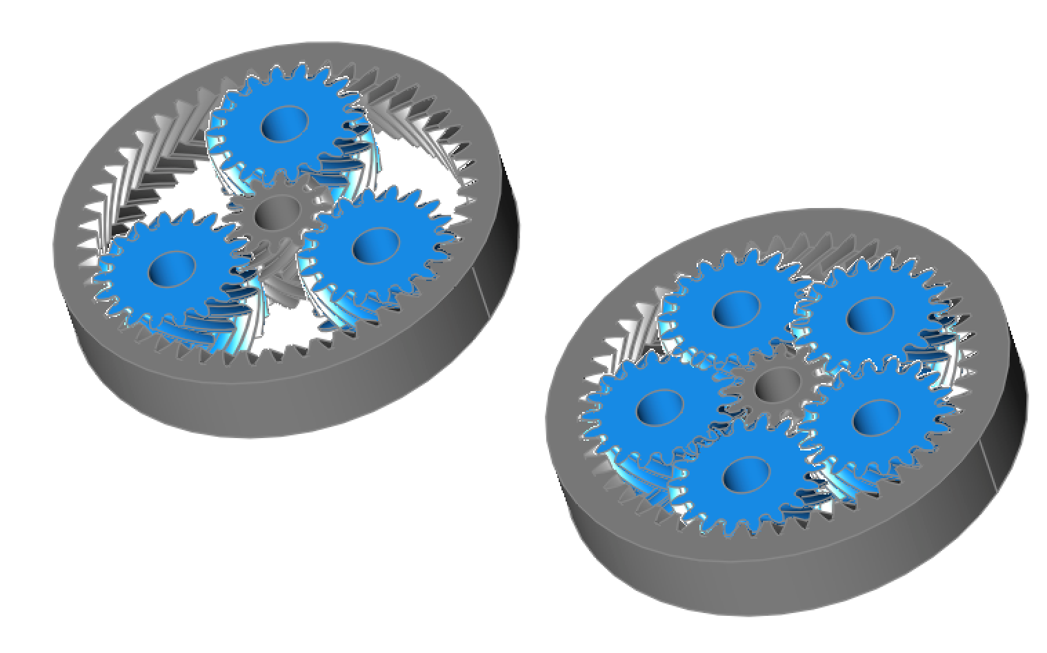
Herringbone Planetary Gear
The Herringbone Planetary Gear part creates a gear with the following parameters:
Module: Tooth size scaling factor sets the size of the teeth.
Sun Teeth Number: Specifies the number of teeth on the central sun gear.
Planet Teeth Number: Specifies the number of teeth on each of the planet gears.
Width: Defines the axial thickness of the gearset.
Rim Width: Specifies the width of the rim that supports the gear teeth.
Number of Planets: Indicates the total number of planet gears in the gearset.
Bore Diameter: Specifies the diameter of the central bore for shaft fitting.
Helix Angle: Defines the helix angle of the planetary gears, affecting the gear tooth alignment
Using the Herringbone Planetary Gear Tool:
- Select the Herringbone Planetary Gear Part type from the category list.
- Set the Module, Sun Teeth, Planet Teeth, Width, Rim Width, Number of planets, helix angle, and bore diameter.
- Press the Create button.
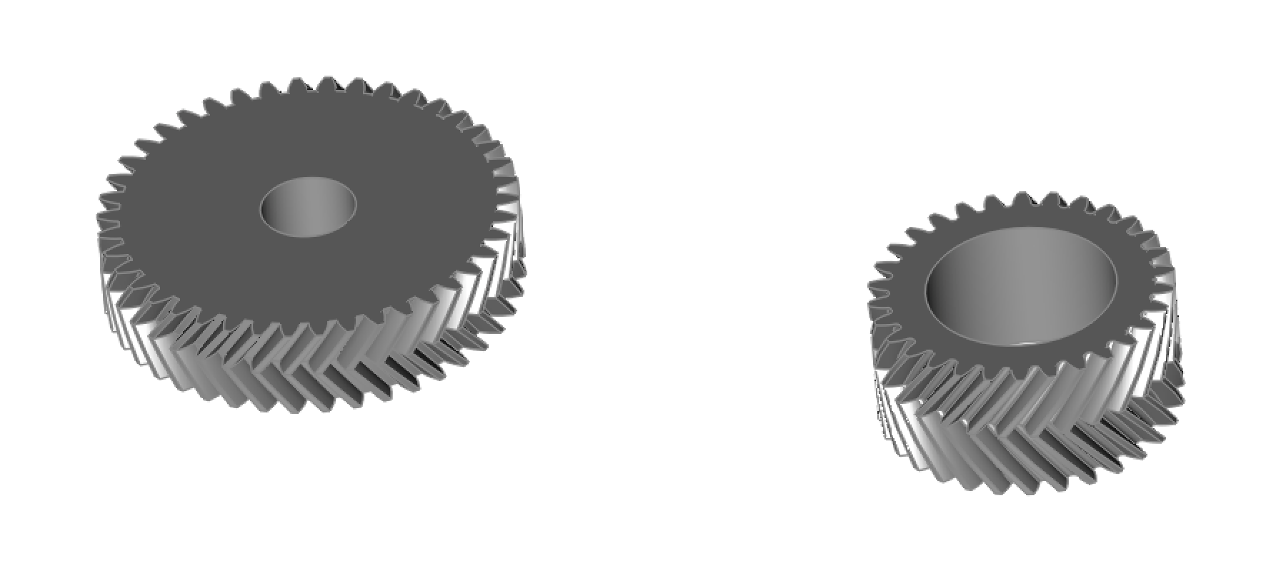
Herringbone Gear
The Herringbone Gear part creates a gear with the following parameters:
Module: Tooth size scaling factor sets the size of the teeth.
Teeth Number: Specifies the number of teeth on the gear.
Width: Defines the axial thickness of the gearset.
Bore Diameter: Specifies the diameter of the central bore for shaft fitting.
Helix Angle: Defines the helix angle of the planetary gears, affecting the gear tooth alignment.
Using the Herringbone Gear Tool:
- Select the Herringbone Gear Part type from the category list.
- Set the Module, Teeth, Width, helix angle, and bore diameter.
- Press the Create button.
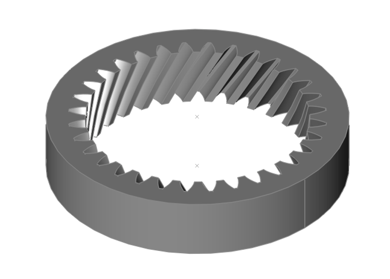
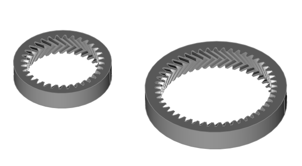
Herringbone Ring Gear
The Herringbone Ring Gear part creates a gear with the following parameters:
Module: Tooth size scaling factor sets the size of the teeth.
Teeth Number: Specifies the number of teeth on the gear.
Width: Defines the axial thickness of the gearset.
Rim Width: Specifies the width of the gear's rim.
Bore Diameter: Specifies the diameter of the central bore for shaft fitting.
Helix Angle: Defines the helix angle of the planetary gears, affecting the gear tooth alignment.
Using the Herringbone Ring Gear Tool:
- Select the Herringbone Ring Gear Part type from the category list.
- Set the Module, Teeth, Width, helix angle, and bore diameter.
- Press the Create button.
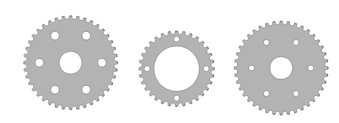
Sprocket
The Sprocket part creates a sprocket with the following parameters:
Number of Teeth: Specifies the total number of teeth on the sprocket.
Clearance: Sets the clearance for the sprocket's tooth engagement.
Bolt Circle Diameter: Defines the diameter of the circle on which the mounting bolts are arranged.
Number of Mount Bolts: Specifies the total number of bolts used for mounting the sprocket.
Mount Bolt Diameter: Sets the diameter of each mounting bolt.
Bore Diameter: Specifies the diameter of the central bore for shaft fitting.
Using the Sprocket Tool:
- Select the Sprocket Part type from the category list.
- Set the Number of Teeth, Clearance, bolt circle diameter, number of mounting bolts, mount bolt diameter and bore diameter.
- Press the Create button.
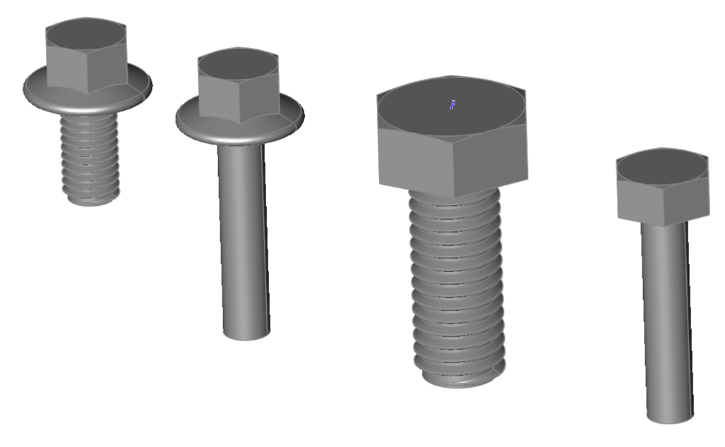
ISO Hex Screw
The ISO Hex Head screw creates a part with the following parameters:
Diameter: Sets the screw size and thread pitch. M3.5 indicates a 3.5MM diameter. The diameter is mapped to one of the following ISO standards:
M1.6-0.3, M2-0.4, M2.5-0.45, M3-0.5, M3.5-0.6, M4-0.7, M5-0.8, M6-1, M8-1.25,
M10-1.5, M12-1.75, M14-2, M16-2, M18-2.5, M20-2.5, M22-2.5, M24-3, M27-3, M30-3.5,
M33-3, M36-4, M39-4, M42-4.5, M45-4.5, M48-5, M52-5, M56-5.5, M60-5.5, M64-6
Length: Defines the length of the screw.
Simple: Excludes threads from the screw if enabled.
Flange: Determines whether to include a flange. Use 0 to exclude a flange.
Using the ISO Hex Screw Tool:
- Select the ISO Hex Screw type from the category list.
- Set the diameter, length, thread, and flange parameters.
- Press the Create button.
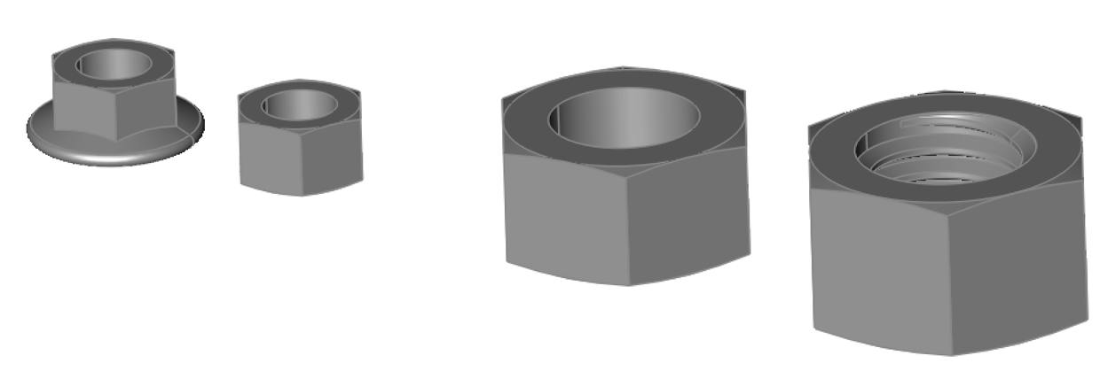
ISO Hex Nut
The ISO Hex Nut creates a part with the following parameters:
Diameter: Sets the nut size and thread pitch. M3.5 indicates a 3.5MM diameter. The diameter is mapped to one of the following ISO standards:
M1.6-0.35, M2-0.4, M2.5-0.45, M3-0.5, M3.5-0.6, M4-0.7, M5-0.8, M6-1, M8-1.25, M10-1.5,
M12-1.75, M14-2, M16-2, M18-2.5, M20-2.5, M22-2.5, M24-3, M27-3, M30-3.5, M33-3.5,
M36-4, M39-4, M42-4.5, M45-4.5, M48-5, M52-5, M56-5.5, M60-5.5, M64-6
Simple: Determines whether a thread is added to the part. Simple excludes a thread.
Flange: Determines whether to include a flange. Use 0 to exclude a flange.
Using the ISO Hex Nut Tool:
- Select the ISO Hex Nut type from the category list.
- Set the diameter, thread, and flange parameters.
- Press the Create button.
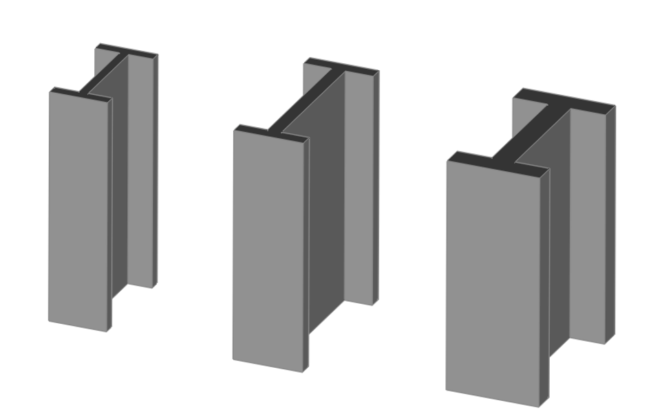
I-Beam
The I-Beam part creates a structural support beam with the following parameters:
Beam Height: Sets the overall height of the I-beam.
Flange Width: Defines the width of the top and bottom flanges.
Flange Thickness: Specifies the thickness of the flanges.
Web Thickness: Determines the thickness of the vertical web connecting the flanges.
Beam Length: Sets the overall length of the I-beam.
Using the I-Beam Tool:
- Select the I-Beam type from the category list.
- Set the height flange width, flange thickness, web thickness and beam length.
- Press the Create button.
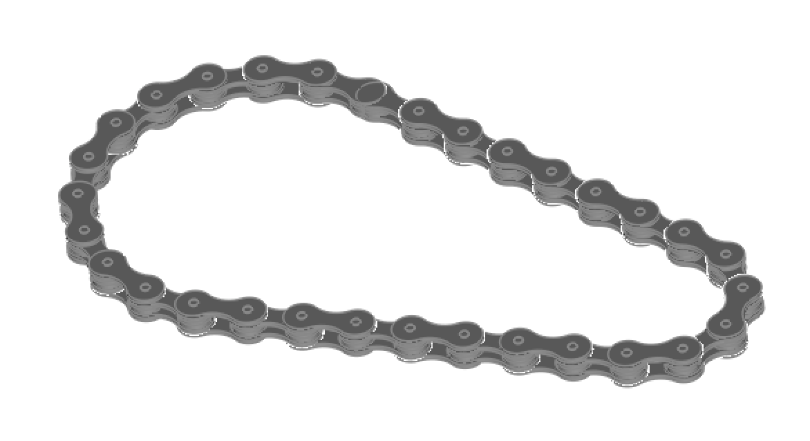
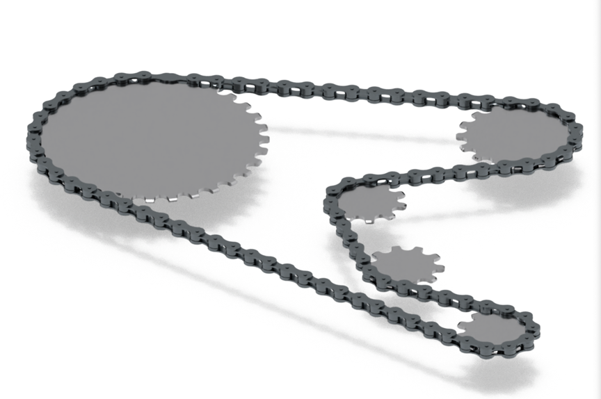
Chain
The Chain part creates a chain with the following parameters:
Sprocket Teeth 1: Specifies the number of teeth on each sprocket.
Positive Chain Wrap 1: the direction chain wraps around the sprockets, True for counter clockwise viewed from positive Z.
Sprocket Locations 1: Defines the center coordinates of the first sprocket.
Sprocket Teeth 2: Specifies the number of teeth on each sprocket.
Positive Chain Wrap 2: Indicates if each sprocket has a positive chain wrap.
Sprocket Locations 2: Defines the center coordinates of the second sprocket.
Using the Chain Tool:
- Select the Chain type from the category list.
- Set the teeth, chain wrap, and locations for each sprocket.
- Press the Create button.
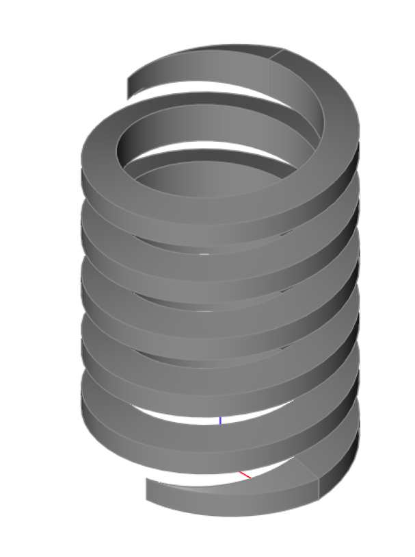
ACME Thread
The ACME Thread part creates a thread that can be unioned to a cylinder or hole with the following parameters:
Thread Type: Specify External or Internal thread.
Size: Choose from 1/4, 5/16, 3/8, 1/2, 5/8, 3/4, 7/8, 1, 1 1/4, 1 1/2, 1 3/4, 2, 2 1/2, or 3 (in inches)
Thread Direction: Right or Left handed thread.
End Finish: Determines how to end the thread from fade, raw, square, chamfer.
Using the ACME Thread Tool:
-
Select the ACME Thread type from the category list.
-
Set the thread type (external, internal), size, length, thread direction and end finish(fade, raw, square,chamfer) .
-
Press the Create button.
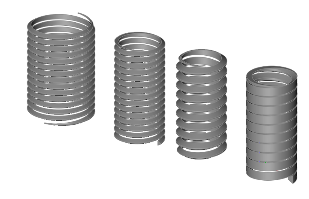
ISO Thread
The ISO Thread part creates a thread that can be unioned to a cylinder or hole with the following parameters:
Thread Type: Specify External or Internal thread.
Diameter: Diameter of thread.
Pitch: Distance between thread intervals.
Length: Length of thread.
End Finish: Determines how to end the thread from fade, raw, square, chamfer.
Using the ISO Thread Tool:
- Select the ISO Thread type from the category list.
- Set the thread type (external, internal), diameter, length, pitch, and end finish.
- Press the Create button.
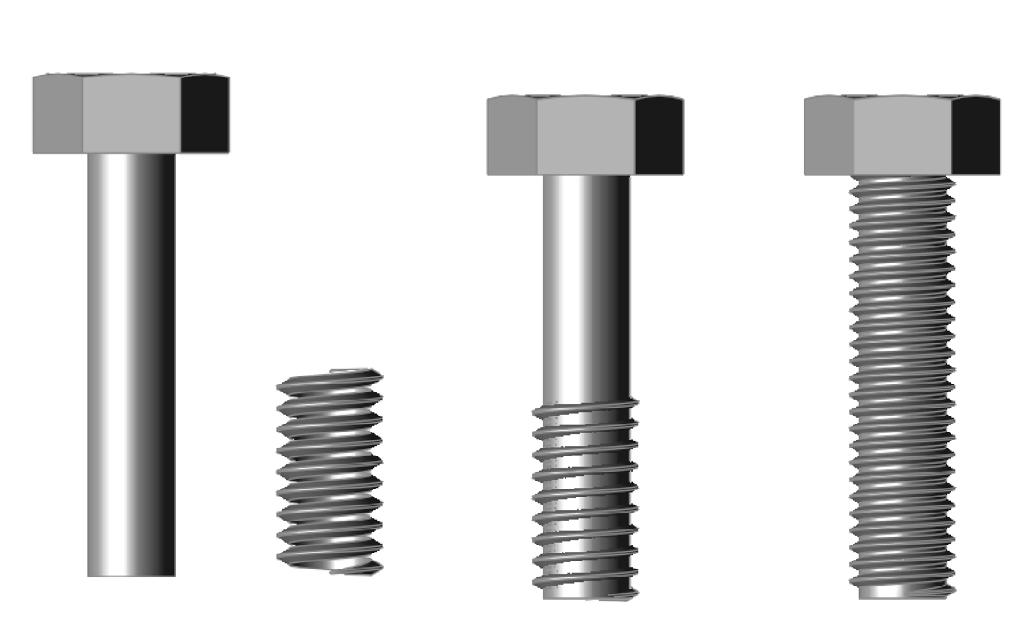
The ISO Thread creator provides a means to create custom threads on your parts. Below is an image of a custom thread added to a simple screw.
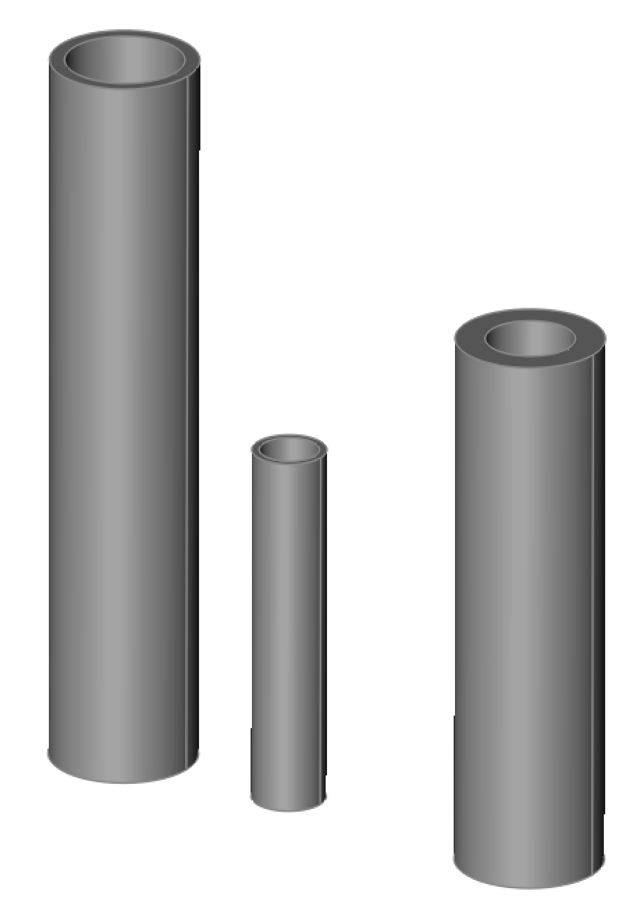
Round Pipe
The Round Pipe part hollow cylinder with the following parameters:
Diameter: Diameter of pipe.
Thickness: Pipe wall thickness.
Length: Length of pipe.
Using the Round Pipe Tool:
- Select the Round Pipe part type from the category list.
- Set the pipe diameter, thickness and length.
- Press the Create button.
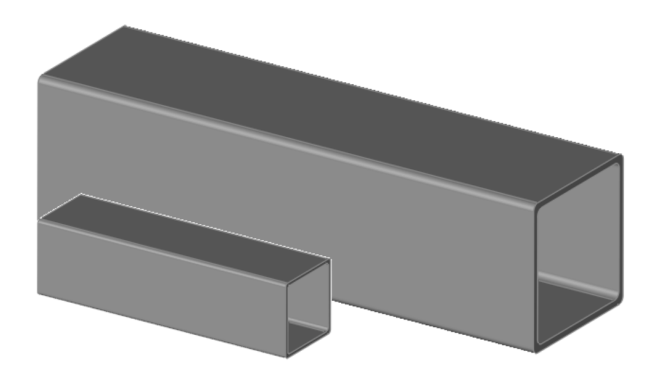
Square Pipe
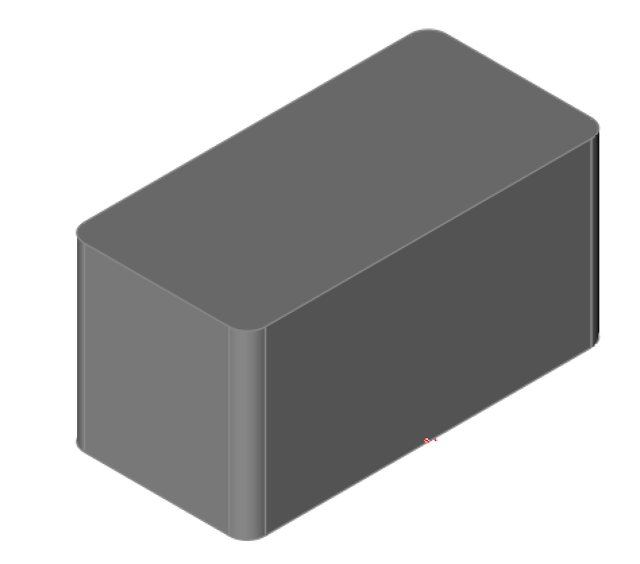
The Square Pipe part hollow square with the following parameters:
Outer Size: Outer wall size.
Inner Size: Inner wall size.
Corner Radius: Fillet radius at corners.
Length: Length of pipe.
Using the Square Pipe Tool:
-
Select the Square Pipe part type from the category list.
-
Set the pipe outer and inner sizes, corner radius and length.
-
Press the Create button.
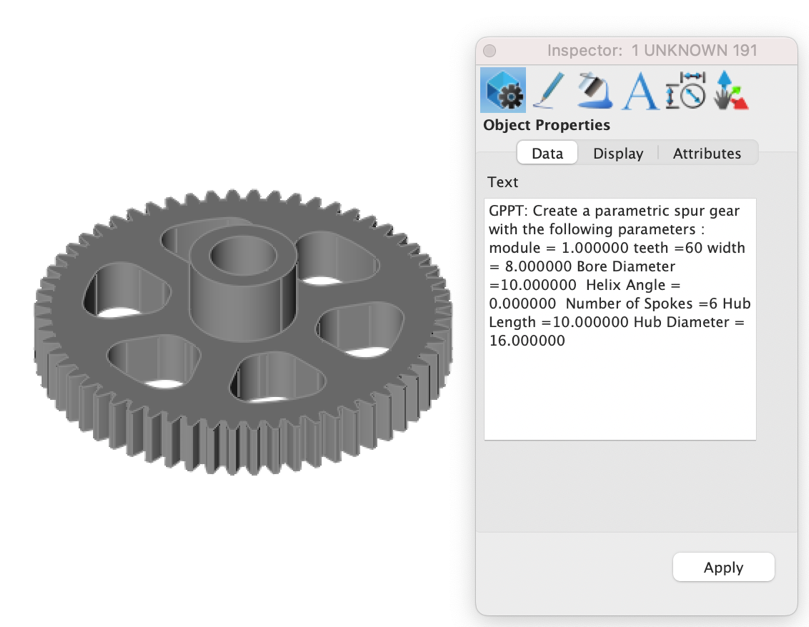
Editing Part Creator Objects
Part Creator attaches the AI instruction that created the part as text to the object. You can later edit the parameters using the inspector.
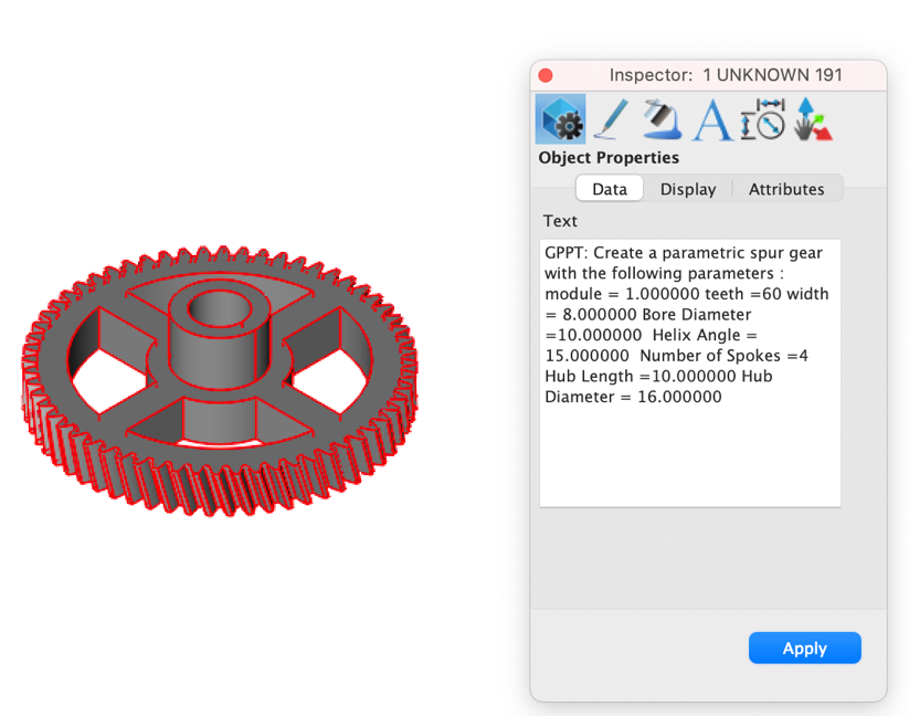
In the following edit session, the number of spokes was increased from 4 to 6 and the helix angle was set to zero.
AI-Powered Text-to-CAD
Copilot Professional introduces an innovative AI-powered Text-to-CAD feature, transforming how users engage with CAD tools. This capability allows users to generate CAD objects using simple, natural language commands. Trained on hundreds of Python CAD scripts, Copilot provides a foundational pathway for creating basic objects directly from text input.
Copilot has been trained to create the following CAD elements and parts plus more:
2D shapes: Text, lines, arcs, circles, rectangles, ellipses, sketches, fillets, polygons.
3D shapes: Prism, box, sphere, cylinder, revolved.
Booleans : Add, cut, interest.
Screw: Cheese head, button had, counter sunk, hex head, pan head, raised cheese, set, socket head.
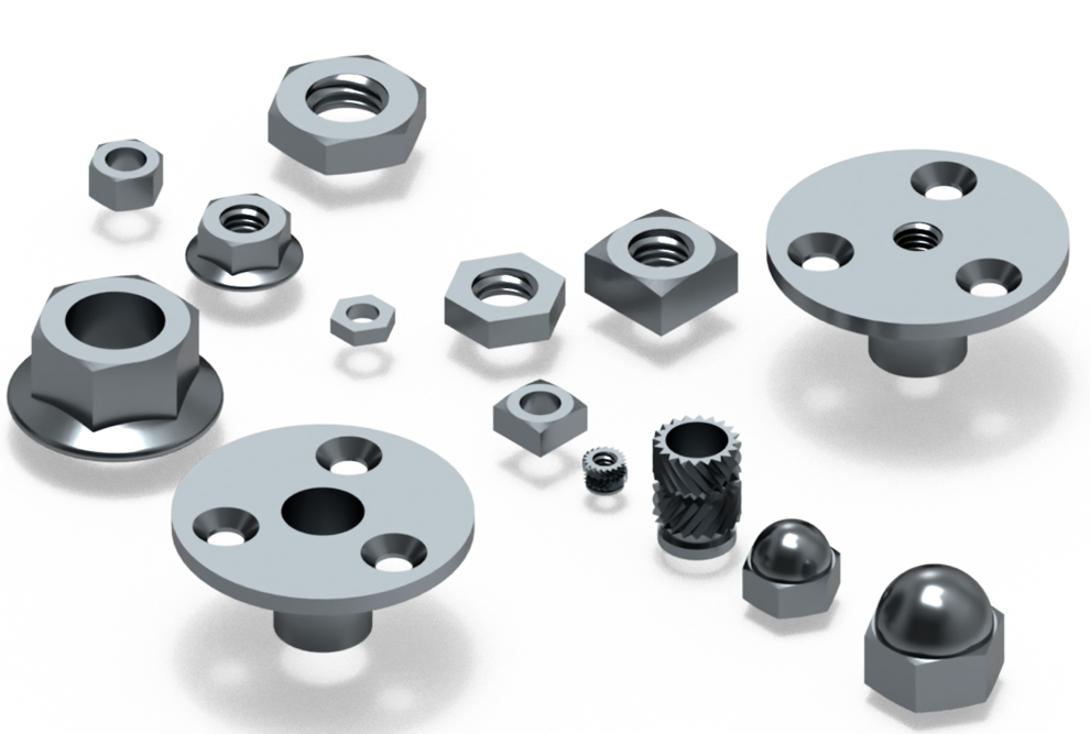
Nuts: Hex, flange, unchamfered, square, brad tee, domed cap, head set.
Disclaimer: This feature represents an exciting first step toward a fully integrated Text-to-CAD experience. While its current functionality is limited by the scope of its training data and ongoing efforts to enhance its language model, we are committed to actively expanding and refining it in future updates.
Examples
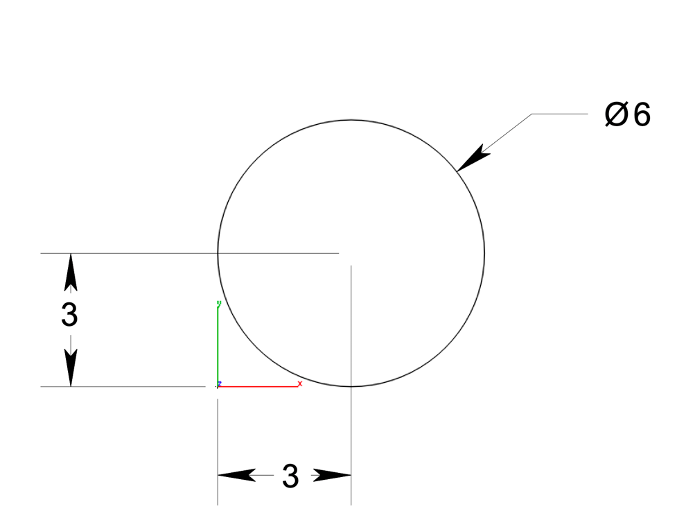
PPT: Create a 6 MM diameter circle centered at (3,3).
PPT: Create a 5 MM line and 7MM x8MM polygon and export to a STEP file.

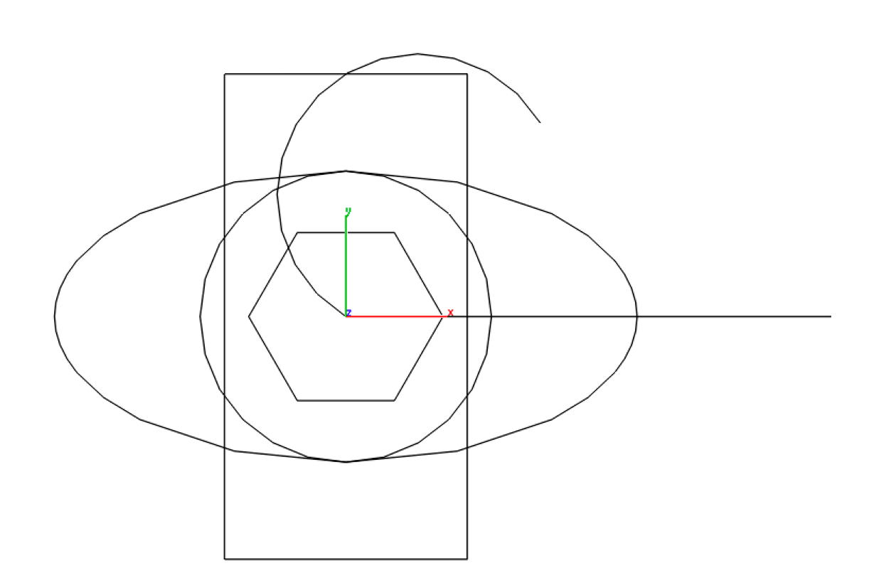
PPT: Create a variety of wireframe curves such as line, rectangle, circle, ellipse, arc, and polygons at the origin.
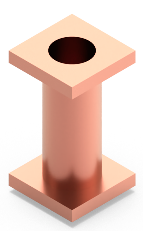
PPT: Create a straight pipe with an outer diameter of 20, inner diameter of 16, and length of 50, with square flanges on each end that measure 30x30 mm and are 5 mm thick.
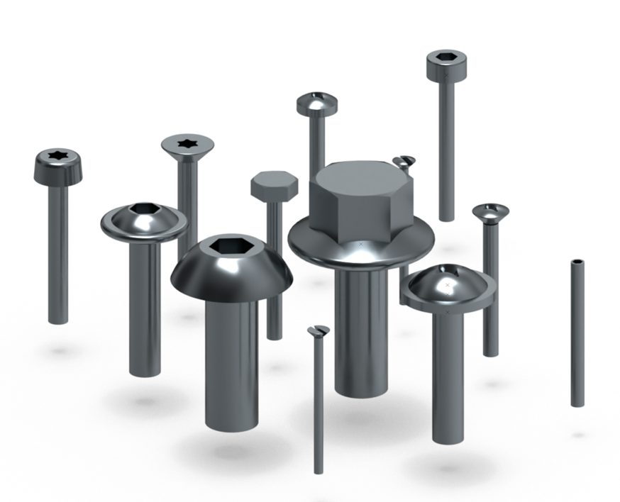
PPT: Create a compound assembly of various screws arranged in a rectangular grid pattern.
PPT: Create a five sprocket chain example
PPT: Create a variety of nuts using Hex Nut, Hex Nut with Flange, Unchamfered Hexagon Nut, Square Nut, Brad Tee Nut, Heat Set Nut, and Domed Cap Nut.
Additional Examples
- DOC: Provide a list curve examples for part creator python scripting.
- DOC: Provide a python script that creates a sketch with a 10x5 MM rectangle with 1mm fillet
extruded 2 MM.
- DOC: Provide a python example how to create a Brad Tree Nut.
- PPT: Create a variety of pipes.
- PPT: Create a variety of screws.
- PPT: Create a variety of gears.
- PPT:Create a Diagonal Line from Origin to (5, 5).
- PPT:Create a Basic Horizontal Ellipse with major radius 10 and minor radius 5.
- PPT:Create a General Thread.
- PPT:Create a Metric Trapazoidal Thread.
- PPT:Create a simple counter sunk screw of size M1-0.25.
- PPT:Create a simple,unthreaded SquareNut of size M5-0.8 and fastener type din557.
- PPT:Create a simple,unthreaded Unchamfered Hexagon Nut of size M5-0.8 and fastener type iso4036.
- PPT:Create a Threaded DomedCapNut of size M24-3 and fastener type din1587.
- PPT:Create a raised cheese head screw of size M1.6-0.5 and fastener type iso7045 with length 10.
- PPT:Create a pan head with collar screw.
- PPT:Create a complex,threaded square hex nut of size M5-0.8 and fastener type din557.
- PPT:Create a simple CounterSunkScrew of size M1.6-0.35 and fastener type iso7046 with length 10.
- PPT:Creates a Raised Cheese Head Screw.
- PPT:Creates a simple (unthreaded) Button Head Screw according to the ISO 7380-1 standard.
- GPPT:Create a hyperbolic gear pair that consists of two gears.
- PPT: Create a Pan Head With Collar Screw of size M3-0.5 and fastener type din967 with length 10.
Executing Python Scripts Directly with Copilot
Copilot Professional also supports the ability to take a script and execute creating a STEP file loaded into your file. Prefix the script with PPT, your instructions, and the python code. The example below demonstrates a question with code.
PPT: Create a 2D 10x20 rectangular sketch with 1 MM fillet radius using the following code:
import cadquery as cq
# shape parameters
width = 10.0 # rectangle width
height = 20.0 # rectangle height
fillet_radius = 1.0 # Fillet radius for the shape's corners
# Common extrusion length for the shape
extrude_length = 10.0 # Length to extrude
# Create a 2D sketch for the shape with a rectangle and filleted corners.
sketch = (
cq.Sketch() # Create a new sketch
.rect(width, height) # Draw a rectangle using the defined width and height
.vertices() # Select all vertices of the rectangle
.fillet(fillet_radius) # Apply fillets to the vertices with the given radius
)
# Extrude sketch by length
shape = (
cq.Workplane("XY") # Start on the XY plane
.placeSketch(sketch) # Place the 2D sketch onto the workplane
.extrude(length) # Extrude the sketch to the same length as the outer shape
)
# Export the resulting as a STEP file.
cq.exporters.export(shape, "results.step")