Verify
The Verify menu provides additional tools for validating and isolating common geometry issues for curves, surfaces, and solids.
Verify
• Show Overlaps
• Show Gaps
• Locate Inflections
• Check Curve Tangency
• Locate Minimum Curvature
• Show Surface Free Edges
• Show Non-Manifold Edges
• Identify Suspect Edges
• Coordinate Compare
Show Overlaps
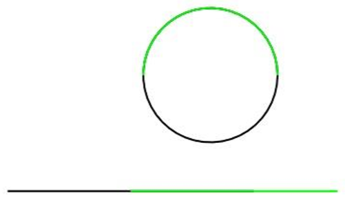
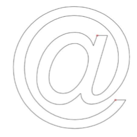
The Show Overlaps command examines selected curves for overlaps. Options are provided to remove the overlaps and to show the overlaps in a thickened red color. The Illustration below shows an arc overlapping a circle and a line overlapping another line.
Example:
- Select the Show Overlaps tool
- Select the curves to be examined. A dialog box reports the number of overlaps identified. Clicking YES will delete the overlaps. Clicking No will highlight overlaps in a thickened red color.
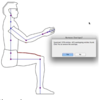
- Click Yes to remove the overlaps.
Show Gaps
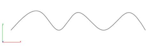
The Show Gaps tool identifies open regions in a curve profile.
Example:
- Select the Show Gaps command.
- Select the curves to examine.

- A dialog box is displayed reporting the results.
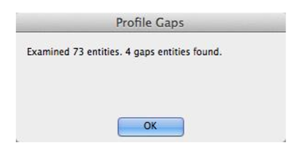
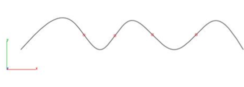
- Gaps locations are marked with point objects.
Locate Inflections
The Locate Inflection tool identifies positions on curves where the second derivative equals zero. This is the location where the sign of the curvature changes. Often inflection points are used as indicators of curve smoothness.
Note:Lines, arcs, ellipses, and conics do not have inflection points.
Example:
- Select a spline to calculate inflection points.
- Inflections are calculated and added as point objects to the file.
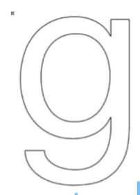
Check Curve Tangency
The Check Curve Tangency examines a collection of curves checking on the tangency at the connection location.
Example:
- Select the Check Curve Tangency command.
- Select two or more curves examine tangency.
- A dialog box is displayed reporting possible issues.
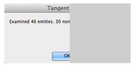
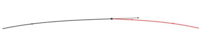
- Point objects are created at those locations where tangency issues exist.
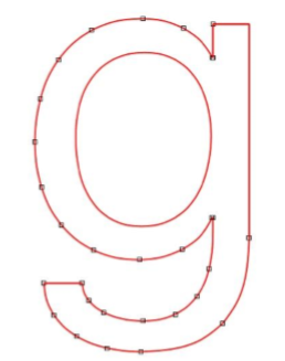
- Use Edit: Show Points to show tangency handles to manually correction issues.
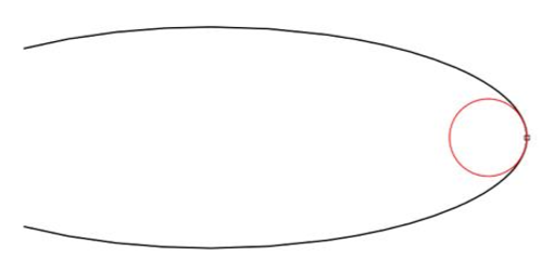
Locate Minimum Curvature
The Locate Minimum Curvature tool identifies the minimum curvature location on a curve. The location is marked with the creation of a circle.
Example:
- Select a curve to calculate the minimum curvature location.
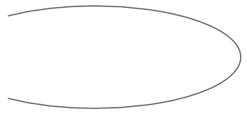
- The minimum curvature location is marked with a circle.
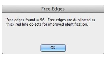
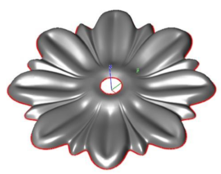
Show Free Edges
The Show Free Edges command creates new curves at surface edges that have only one face attached. The new curves are highlighted in red. Use Undo to remove the curves.
Example 1:
- Select the Show Free Edges command.
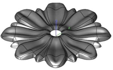
- Edges are recreated as curves highlighted in red. A dialog box indicates how many free edges were found
Example 2: Using Free Edges to Convert to Solid
- Hide the surface from the previous command, leaving just the free edges.
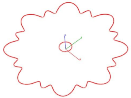
- Select the Cover tool from the surface palette and select all the curves to create a planar surface.
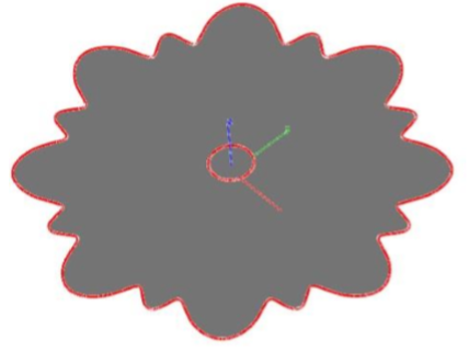
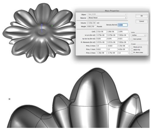
- Select the Stitch tool to combine the surfaces into a water tight volume, suitable for mass property calculations or shelling modeling operations.
Show Non-Manifold Edge
The Show Non-Manifold Edge tool identifiers edges in a solid part that have more than 2 shared faces.
Example:
- Select the Show Non-Manifold Edge tool.
- Select the solid part to examine.
- Non-Manifold edges are displayed as red lines added to the drawing file.
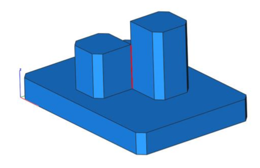
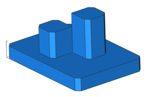
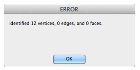
Identify Suspect Edges
Creates a point, edge, or face along a feature that appears to have either topology or geometry issues.
Example:
- Select the Identify Suspect Edges tool.
- Select the solid part.
Coordinate Compare
This tool will precisely compare a set of points to a NURB model. For data points, you can select a point cloud or mesh object.
Depending on the point data set size, this tool is computationally heavy. However, the tool is multiprocessor aware and will thread according the comparisons.
