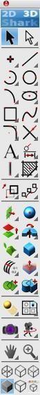
Main Tool Palette
The startup screen displays the Main Tool Palette in the upper left corner of the window. This tool palette is your primary interface to the wide variety of commands available in the application. These commands include wireframe, surface, solid, and tools to modify. From left to right, top to bottom, an overview description of these tools follows.
Tool Palette Descriptions
General Purpose/Wireframe Tools

Select – Select an object to modify.

Deep Select – Select and modify objects within groups or control vertices.

Point – Tools for creating points.

Line – Tools for creating lines.

Arc – Tools for creating arcs.

Circle – Tools for creating circles.

Conic – Tools for creating conics.

Ellipse – Tools for creating ellipses.

Polygon – Tools for creating polygons.

Spline – Create and modify spline entity tools.

Fillet/Chamfer – Fillet and chamfer curve tools.

Trim – Trim, relimit, divide, join curve utilities.

Text – Create horizontal, along curve, and at angle text.

Dimension – Tools for annotating your drawing with dimensions.

2D Architectural – Tools for drawing walls, windows, doors, and attached groups to walls.

Region Hatch & Fill – Tools to hatch and fill an inside region.

Transforms – Tools for translating, rotating, mirroring, scaling objects.

Advanced Transforms – Tools for transforming objects as arrays, paths, and connections.
Surface and Solid Modeling Tools

Surface From Curves – Creates surface from curves or position (planar).

Solid Primitives – Creates simple solids such as blocks, slabs, cones, and cylinders.

Surface From Surface – References other surfaces to create surfaces.

Solid From Profiles – Creates solids from curve profiles.

Surface Utilities – General purpose surface utilities.

Solid Features – Creates feature-based solids such as fillets and chamfers.

Surface Local Operations – Tools that operate on a surface.

Solid Local Operations – Tools that operate on a face.

Advanced Surface Utilities – Additional surface utilities such as adding or subtracting surfaces.

Solid Utilities – Additional solid utilities such as adding or subtracting solids.
More Tools

Lights – Creates light objects for rendering.

Model To Sheet – Makes 2D drawings from 3D objects.

PhotoRender – Tools for creating photorealistic renderings.

Animation – Fly by, walk through and object-based animations.

Dynamic Zoom – Dynamically zoom, rotate or pan a view.

View – Zoom up or down to specified user area.
Display Toggles

Wireframe – Displays model in wireframe line mode.

Hidden – Displays model in hidden line mode.

Hidden Dim – Displays hidden lines lighter than visible lines.

Shaded – Displays model in Gouraud or Phong OpenGL.

Perspective – Turns perspective on or off.

View Props – Displays a dialog that allows you to change specific settings for the current view.
Floating Palettes
This software product uses floating tool palettes. Floating tool palettes contain options that you frequently use to create drawings and designs. To select an option in a floating tool palette simply press and release the mouse over the option.

If you Control-click (right-click) in the title bar of a floating tool palette you will get a menu of options that further customize the floating tool palette.
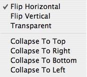
Flip Horizontal and Flip Vertical will change the tool palette between a left to right palette and a top to bottom palette.
Transparent hides the lines of the palette so only the tools appear. This feature is available for Mac only.
Collapse to Top, Collapse to Right, Collapse to Bottom or Collapse to Left will collapse the palette when the cursor is not over the tool palette.
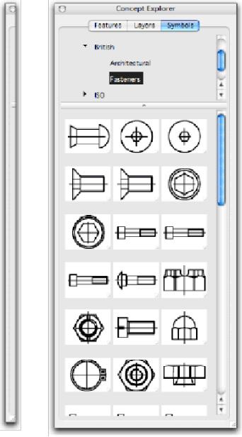
Not only does collapsing work with tool palettes, but you can use it with other dialogs as well, including Concept Explorer. Auto collapse and expand is a great way to efficiently use screen area.
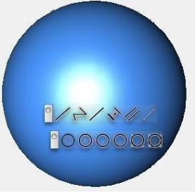
Tools with a right pointing arrow (located at the bottom right corner of the tool icon) indicate that a sub palette exists for that tool option. Sub palettes are a collection of tools that are similar in function. A sub palette can be made visible by clicking on the arrow portion of the icon. A sub palette will disappear once you have made your selection and release the mouse button.
A sub palette can be made to stay permanently by dragging your mouse beyond the far-right extents of the palette and “tearing” it away from its parent.
To remove any palettes from the screen simply press your mouse button in the upper left corner of the window.
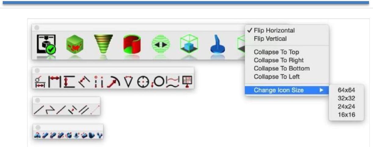
Change Icon Size
You can now modify a tool palette to use larger or smaller icons. Right click on the tool bar header to display a popup menu for “Change Icon Size”. This menu now provides options for 64,32,24 and 16-pixelsized icons. The default icon size is 32x32.
Tear Away Menus
Many of the floating tool palettes have additional options. More options are available if the icon displays a right pointing arrow in the lower right-hand corner of the icon. To access these options, press the mouse button on or near the arrow. As you continue to hold the mouse down, a sub tool palette will appear with additional options. Move the mouse to the desired sub tool palette option and release the mouse button. If you move the mouse beyond the right extents of the palette, the menu will “tear” away from the parent menu and stay permanently on the screen (or until you close the palette).
Tip: Select the Preferences command and click OK to save all of the currently displayed tear away menus and their associated screen locations. This will store the locations in the preference file so that you don’t have to relocate menus to your preference each time you start the application.
Tool Tips
As you move the cursor over any icon, a brief description of the corresponding command is displayed within the prompt window (overlays the x, y, z display). Tool tips can be turned on or off through the General Preferences setting, on the SharkCAD menu.
Tip of the Day
The Tip of the Day dialog box displays useful tips, reminders, and hints about getting the most out of the application. The Tip of the Day dialog appears upon launching the application. Select the next button to display additional tips. Check the “Show tips at startup” button to have the tips dialog box display every time the program is launched. You can also show the tips dialog box from the Help menu.
The tip of the day dialog reads strings from the tips.ini file located in the Environ folder. You can customize the tips by modifying the contents of this file.