Solids From Profiles
Solids From Profiles
A profile is a closed 2D section created from curves, lines or polygons. The curves must lie in the same plane. A 2D profile can be lathed, swept, extruded or sectioned to create a solid. When a profile is used to create a solid, SharkCAD creates a parent/child relationship between the profile (parent) and the solid (child). Any changes made to the parent will regenerate the child. For example, if you lathe a rounded rectangle polygon, you can edit the polygon radius and the solid will regenerate for the new shape.
Lathe Solid
The Lathe Solid command rotates any closed 2D polyline, circle, ellipse, closed spline or polygon. You can also lathe groups of closed curves. You cannot lathe a profile that intersects upon itself (possible for polylines, splines, and polygons).
Using the Lathe Solid tool
Select a closed profile (curves, groups). Select a line for the revolution axis.
Use the Data Entry Fields to adjust angle and draft. Note: You can specify positive or negative angles.
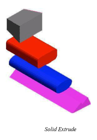
Extrude Solid
The Extrude Solid command takes a profile and extends the shape a user specified distance. You can extrude 2D polylines, circles, ellipses, closed splines, and polygons. There are five extrude methods.
Distance Extrudes a user defined distance. Uses profile normal for extrusion direction.
Vector Extrudes a distance and direction defined by two points.
To Entity Extrudes a direction defined by two points and terminates at a used defined surface or solid.
Mid Plane Extrudes on both sides of the profile.
Thin Extrude Extrudes open or closed curves with a thickness and distance.
Many of the extrusion options include a draft angle. The draft angle default is zero, which results in the sides of the solid being parallel to the profile normal. If the draft angle is positive, the sides will be forced inward. Likewise, negative draft angles will force the sides outward. Some draft angles and extrusion heights will cause the solid to self intersect. If this happens you must reduce the draft angle or increase the extrusion height.
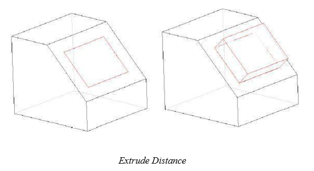
Distance
Distance extrudes normal to the plane of the profile a specified distance. The distance can be positive or negative.
Using the Extrude Distance tool
Select a closed profile (curves, groups).
Use the Data Entry Fields to adjust the extrusion distance.
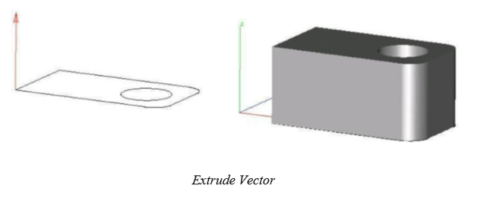
Vector
Vector extrudes a profile along a vector whose distance is defined by two user-supplied points.
Using the Extrude Vector tool
Select a closed profile (curves, groups).
Click two points defining the direction and magnitude of the extrusion.
Use the Data Entry Fields to adjust the extrusion distance.
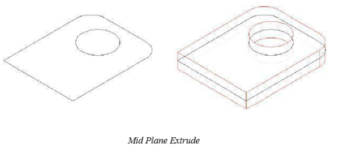
Mid Plane
Mid Plane extrudes a profile in both directions using the plane of the profile.
Using the Extrude Mid Plane tool
Select a closed profile (curves, groups).
Use the Data Entry Fields to adjust the extrusion distance.
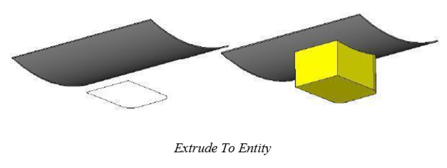
To Entity
To Entity extrudes along a vector terminating at a surface or solid. The terminating body is not unioned with the extruded body.
Using the Extrude To Entity tool
Select a closed profile (curves, groups).
Select a terminating surface or solid
Use the Data Entry Fields to adjust the draft.
Thin Extrude
Thin Extrude extrudes an open or closed profile by a vector and thickness.
Using the Thin Extrude tool
Select one or more curves.
Click two points defining the direction and magnitude of the extrude.
Use the Data Entry Fields to adjust the height and draft.
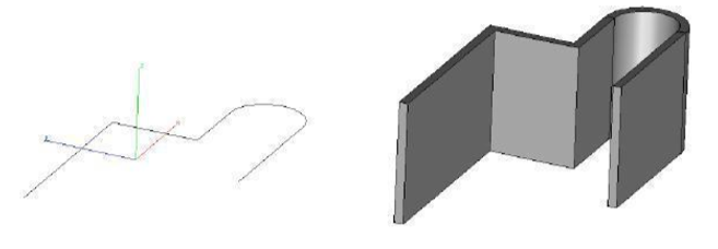
Use the Option key to toggle between sides, right side and left side, for offset direction.
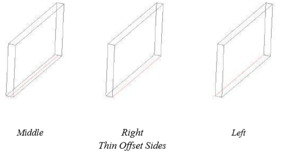
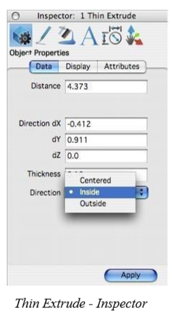
The Inspector includes edit fields for distance, direction, thickness, and offset options for centered, inside, and outside.
There are certain situations where the Thin Extrude tool will fail and produce the error message “Gap cannot be filled”. This error message results from curves that cannot be extended (this will often be noticed with splines). One means to work around this is to thicken the extrusion to the opposite offset side. You can accomplish this by specifying a negative offset value.
One Rail Sweep Solid
A sweep is similar to an extruded solid except instead of an extrusion vector you specify a sweep path. A sweep path can be a line, circle, arc, ellipse, conic or spline.
The One Rail Sweep has two pull downs for options on the Prompt window. The first drop-down controls how the profile orientation sweeps along the rail. It contains the following three options: Sweep In Place (profile is not translated or aligned to path).
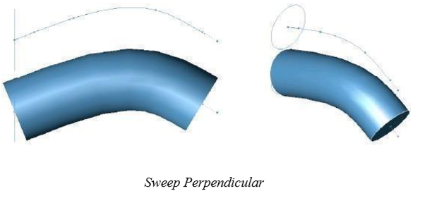
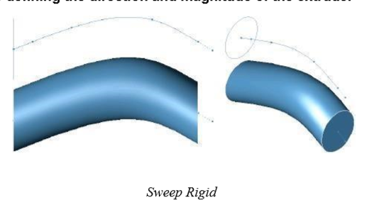
Sweep Perp (profile is translated and aligned perpendicular to path). Sweep Rigid (profile orientation is maintained regardless of path tangent).
The next drop-down controls how the profile is terminated. It contains the following three options:
Curve extents (profile is swept across entire curve extents). To Body (profile is terminated at a surface or solid). Between Points (user specifies two points on the path).
Sweep Perpendicular rotates the sweep profile to be perpendicular to the take-off path. Sweep in Place leaves the sweep as is; no aligning of the profile occurs with this option. Sweep to Entity sweeps the profile along the given path and terminates to a reference surface or solid.
Sweep Options
The Options button displays the Sweep Options dialog. Here you can further control the behavior of the tool.
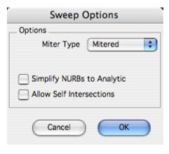
Miter Type
Controls how material is added along paths that are not tangential.
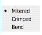
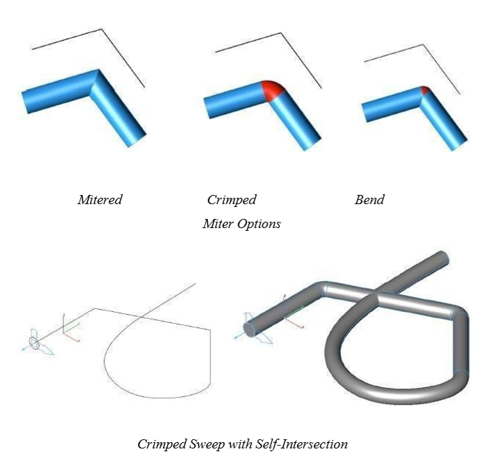
Mitered Corners are finished with two 45-degree angled edges.
Crimped Corners are finished with a curved section connecting the two edges.
Bend Corners are finished with a combination of curved sections and angled edges.
Bend Radius
Displayed when using the Bend Miter type to set the radius added material.
Simplify NURBS to Analytics
Converts NURBS surfaces into analytics, where possible. Analytics typically take up less memory and provide faster calculations.
Allow Self Intersections
Enables sweeps to self-intersect along the path.
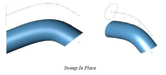
Sweep In Place
Sweep In Place preserves the starting orientation of the profile with respect to the path.
Using the Sweep In Place tool
Select profile curves.
Select rail curve for sweep path.
Use Data Entry Fields to adjust optional twist and draft.
Sweep Perpendicular
The Sweep Perpendicular method realigns the starting orientation of the profile with respect to the path.
Using the Sweep Perpendicular tool
Select profile curves. Click one point defining profile origin. The origin of the profile is transformed to the start of the path.
Select rail curve for sweep path.
Use Data Entry Fields to adjust optional twist and draft.
Sweep Rigid
The Sweep Rigid method preserves the starting orientation of the profile throughout the entire sweep.
The profile is never rotated or aligned to the path.
Using the Sweep Rigid tool
Select one or more curves.
Click two points defining the direction and magnitude of the extrude.
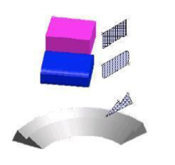
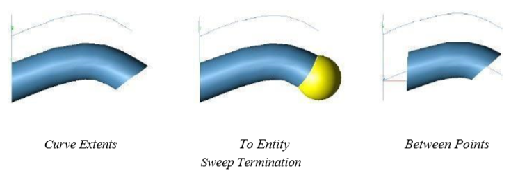
Sweep Termination
Sweeps can be terminated by curve extents, to body or between points. The following image demonstrates the three termination methods.
Curve extents (profile sweeps across entire curve extents). To Body (profile is terminated at a surface or solid). Between Points (user specifies two points on the path)
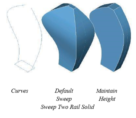
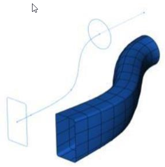
Two Rail Sweep Solid
The Two Rail Sweep Solid tool creates a swept solid by sweeping a closed curve between two rail curves. The rail curves define the orientation and scale of the profile as it moves between the two curves.
Using the Two Rail Sweep Solid tool
Pick a profile to sweep.
Pick the first rail path.
Pick the second rail path.
Hold the Option key at step one if you want to maintain the profile height, as it is swept.
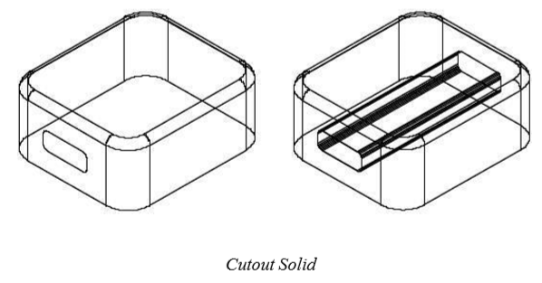
CutOut Solid
CutOut Solid is a method for quickly subtracting material from a solid.
Using the CutOut Solid tool
Select a profile to cutout.
Select a solid.
Click two points defining the direction and distance for the profile to be swept and removed from the solid.
Use the Data Entry Fields to adjust the distance and draft angle.
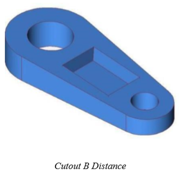
CutOut By Distance
The CutOut tool supports material cutouts by distance. The direction is relative to the selected face upon which the 2D profile lies.
Using the CutOut By Distance tool
Click the CutOut tool. Click the drop-•down on the Data Entry window and choose Distance.
Select the face upon which the profile lies.
Select the curves to cutout.
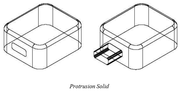
Protrusion Solid
A protrusion feature is a quick method for adding material to an existing solid.
Using the Protrusion Solid tool
Select a profile to protrude. Select a solid.
Click two points defining the direction and distance for the profile to sweep and be added to the selected solid.
Use the Data Entry Fields to adjust the distance and draft angle.
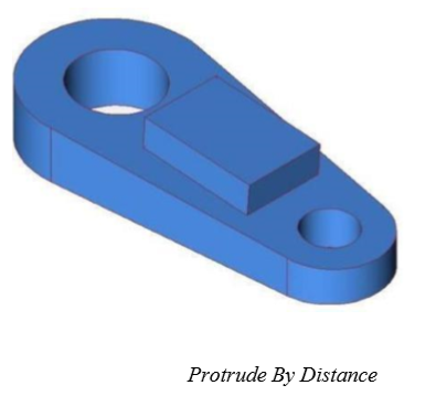
Protrude By Distance
The Protrude tool supports protrusions by distance. The distance is relative to the selected face uponwhich the 2D profile lies.
Using the Protrude By Distance tool
Click the Protrude tool. Click the drop-•down on the Data Entry window and choose Distance.
Select the face upon which the profile lies.
Select the curves to protrude.
Skin Solid
A Skinned Solid is created from a collection of closed 2D profiles. There are two methods for skinned solids. The first creates a solid from the given profiles. The second allows the user to select guide curves that control the shape between the sections. The profiles must be selected in the order they create a solid (use Shift select). If a profile has more than one curve, be sure to group the curves.
The Skin Solid data properties attributes, located in the Inspector, now includes an option for turning on/ off Match Vertices. This option suppresses the vertex-matching algorithm, which ensures that all profiles consist of the same number of co-edges. A heuristic approach is used to determine which vertex pairs are good matches. Profile co-edges are then split where additional vertices are needed. This option is forced to TRUE if the co-edge numbers of the profiles are not equal. Its default is true.
Skinning with Centerline Path
Skinning is the process of constructing a NURB surface between sections. Skins in ViaCAD can be open resulting in a NURB Surface or closed creating a Solid. V12 introduces the ability to specify a path. The path defines the flow of the surface between the sections. Specifying a path means you may be able to define less sections, which may produce a more overall smooth surface.
Using the Skin Solid tool
Hold the Shift key and select profiles; release when done. There are no Data Entry Fields options for this tool.

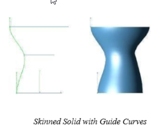
Guide Skin Solid
This tool guides curves. The resulting body will pass through the provided guide curves. Be sure your guide curve passes precisely through the profile section or it will be ignored. Guide curves must be single (no groups), curvature continuous curves. You may have any number of guide curves.
Using the Guide Skin Solid tool
Select the second icon in the message line for skin with guides.
Hold the Shift key and select profiles;; release when done.
Hold the Shift key and select guide curves;; release when done.
There are no Data Entry Fields options for this tool.
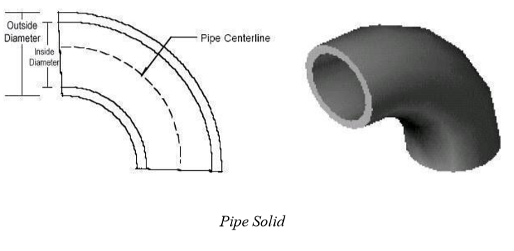
Pipe
The Pipe Solid command provides a rapid feature for creating pipes and tubes. To create a pipe you select a curve which is the pipe centerline. Then specify the pipe inner and outer diameter values.
When a pipe is created SharkCAD creates an intelligent link between the solid and the pipe centerline. Whenever the pipe centerline is moved or modified, the pipe solid will regenerate. In addition to changing the pipe path, you can perform a Window:Inspector to verify or change the pipe diameter values. Specifying an inside diameter of 0 will provide a pipe without a hollowed inside.
Using the Pipe tool
Select the curve for the pipe center line. Use the Data Entry Fields to adjust the inner and outer diameter values (or the Inspector).
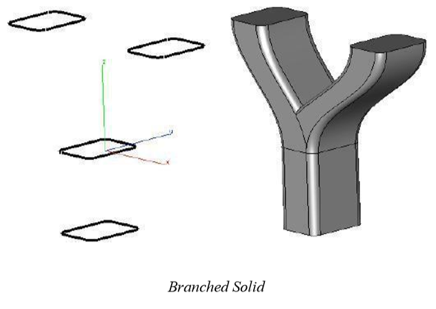
Branched Solid
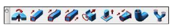
The Branched Solid tool is used to create shapes with profiles that resolve two or more branched conditions. The Branch tool is located as the last item within the Solid From Profiles tool palette.
The Branch tool requires the user first select a collection of profiles for the trunk. The trunk profiles represent the core set of surfaces from which all others join. The second set of profiles are called branches. These branches are smoothly integrated into the trunk profiles. SharkCAD supports up to five branches from the trunk.
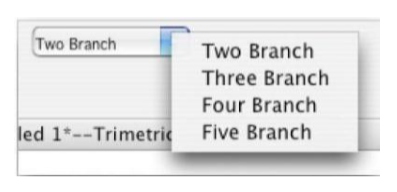
Using the Branched Solid tool
Select the Branched Solid tool from the Solid From Profiles palette. Select the Number of Branches from the drop-•down menu.
Hold the Shift key and select one or more profiles for the trunk body.
Hold the Shift key and select one or more profiles for the first branch.
Repeat for the number of branches desired.