Export
The export option provides a means to export geometry data to a wide variety of applications.
Export options include precise and facetted format.
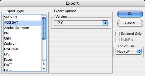
In addition to settings unique to a file format, the export dialog has two checkboxes related to all exports. These two checkboxes are:
Selected Only
This option saves only objects which are selected with the Arrow tool.
Multi File
Saves each selected solid as an individual file. For example, if your file contains 10 solid objects, each object will be stored as a separate file. This option is only available if Selected Only is enabled.
If an ASCII based export format is selected, the following option is supported:
End of Line
This option sets the end of line terminator for Mac, PC or Unix.
The following export file formats are supported:
SharkCAD
This option will export the file as a SharkCAD file. This is useful for sharing data with older versions as you can specify the version upon export.
ACIS® SAT
Exports curves, surfaces, and solids using Spatial Technology's ACIS® kernel. The following export option is supported:
Version
Specifies the format version to use for export.
Adobe Illustrator®
This format exports the current display image to Adobe Illustrator®. There are no options for this file format.
BMP
The BMP file format reads bit mapped image files. This type of file is useful for sketching data on top of scanned images. There are no export options for this file format.
CGM
This format exports Computer Graphics Metafile (CGM) file. The resultant file is created from the 2D display of the data and is therefore dependent on the view in use at the time the export is created. There are no options for this file format.
*3D PDF*
3D PDF exports the data into a 3D format supported by Adobe Acrobat Reader. The following export options are supported:
*Facets*
The solid modeling data is tessellated into display facets and shared with 3D PDF. Some complex NURB types in ViaCAD are not supported in Adobe requiring this option.
*NURB*
Solid modeling data is shared as precise ACIS data. This option generally provides very smooth looking models in Acrobat.
*Dimensions and Annotations*
Text, curves, and dimensions are converted into thin surfaces and exported to 3D PDF.
*CATIA® v4*** (SharkCAD Pro Only)
Exports surfaces and solids into Dassault System's CATIA® v4 file format. There are no options for this file format.
*CATIA****®*** *v5*** (SharkCAD Pro Windows Only)
Exports surfaces and solids into Dassault System's CATIA® v5 file format, for PC only. There are no options for this file format.
*DWG and DXF*
Exports the file as an AutoCAD® DWG or DXF file. The following export options are supported:
*DWG and DXF Format*
Specifies the format version to use for export. The following formats are supported:
*R12*
Pre ACIS® version of AutoCAD® that does not support surfaces or solids. Surfaces and solids export their facet display list using FACE3D entities. This version of AutoCAD® also did not support ellipses, conics, and splines. These types are converted automatically as polylines.
*R13*
ACIS® data is supported including surfaces, solids, ellipses, and splines.
*R14*
Same data conversion as R13 but uses a newer version of ACIS® for curves, surfaces, and solids.
*R2000*
Same data conversion as R13 and R14 but uses a newer version of ACIS® for curves, surfaces, and solids.
*DWG and DXF File Units*
Since both DXF and DWG are unitless formats, this option internally scales the data for the specified unit settings.
Tip: *During DWG and DXF export the following conversions are applied: Hatch patterns are converted to lines.* *Groups are automatically exploded into individual geometry types. Draw views are automatically flattened into the sheet.ACIS data only supported in DXF.*
EPS
This format exports an encapsulated postscript file (EPS). There are no options for this file format.
Facet
This format exports the display mesh using a format defined by Lockheed. The facet file format includes normals per vertex and color information. There are no options for this file format.
FACT
This file format is used by the Electric Images Animation System.
IGES
The IGES option exports curves, surfaces, and solids out to the Initial Graphics Exchange Specification (IGES) format. The following export options are supported:
Flavor
The flavor pulls down automatically assigns settings for particular applications that include AutoCAD®, SolidWorks®, Pro/E®, and Alias.
Write MSBO #186
This option will create Manifold Solid Boundary Objects when solids are exported into the IGES file.
Trimming Curve Preference
Specifies the trimming curve preference used to define trimmed surfaces. Check 2D parametric to have the 3D trim curves driven from the 2D parametric curves. Check 3D model space to have the 2D parametric curves driven from the 3D trim curves.
IGES File Units
Specifies the units for the exported file. The application will internally scale the data to the appropriate unit type.
JPEG
This option will capture and save the entire display screen to disk in the JPEG format.
PICT (Macintosh® only)
Exports objects displayed on the screen into the Apple PICT format.
RAW
This format is used primarily for exporting triangular facet geometry to the popular Persistence of Vision ray trace utility. To convert a RAW file into POV, use the POV utility program RAW2POV. There are no options for this file format.
STEP
Exports files that adhere to the STEP Standard AP203. There are no options for this file format.
Tip: This translator only supports modeling data such as curves, surfaces, and solids. Drafting and annotation data is not exported.
Collada Support (DAE)
Exporting of mesh, surfaces, and solids is supported using the Collada file format. Collada (COLLAborative Design Activity) is a facet based exchange format identified with the .dae filename extension. This format does not support annotations, curves,or textures.
STL
The STL option exports data in a format suitable for creating stereo lithography files. This format consists of a facetted representation of your surface or solid data. The following export options are supported:
STL Format
Specifies the storage format to use for export.
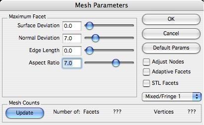
After initiating the export, you will be prompted with the Mesh Parameters dialog box. This dialog gives you control over the facet resolution to use for export.
The precise, mathematical representation of a solid or surface must often be converted into a collection of imprecise planar facets. These facets, for example, may be used to export a model to the STL format, and when changing a solid or surface (Edit: Change Object Type…) to a mesh. The amount of error that results from this conversion is controlled by the settings in the mesh parameters dialog box.
Convert to Mesh Dialog
During the conversion, vertex points are distributed on the surface or solid. These vertices are then grouped into 3-sided and 4-sided facets. The conversion is deemed acceptable when the generated vertices and facets satisfy the settings. The five (5) available settings are Surface Deviation, Normal Deviation, Edge Length, Aspect Ratio, and STL Facets. These settings are defined in the sections below.
Change the facet settings as needed in the dialog, then click the Update button to see the number of facets and vertices generated. Determining the combination of settings that will work for a given situation can be a little bit of an art. If one setting becomes too tight, the other settings will have no effect. If one setting becomes too loose, it will have no effect.
Keep in mind that under “real” circumstances the faceting algorithm only uses the settings if possible. It is often not possible to satisfy all settings simultaneously. In this situation, the algorithm decides which settings to “loosen” or ignore.
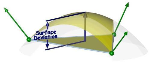
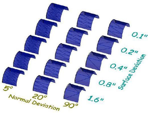
Surface Deviation
This setting controls the maximum allowed distance between any point on the actual surface or solid and the facet representing that point. The exaggerated figure below shows the largest distance between a patch on the actual surface (yellow) and the corresponding planar facet (brown).
Normal Deviation
This setting controls the maximum allowed angular difference between any normal on the actual surface or solid and the corresponding interpolated normal on the facet.
Edge Length
This setting controls the maximum allowed edge length of any given facet.
Aspect Ratio
This setting controls the maximum allowed aspect ratio of any given facet.
STL Facets
This setting will force the facets generated to be suitable for stereolithography usage. This setting is usually used when exporting STL files.
Text
Exports text entities into an ASCII file containing the text characters. There are no options for this file format.
VDA (SharkCAD Pro Only)
VDA-FS is a CAD data exchange format for the transfer of surface models from one CAD system to another. The name stands for “Verband der Automobilindustrie - Flächenschnittstelle”, which translates to the “organization of the automotive industry - surface translation format”. This file format standard was specified by the German organization VDA. VDA-FS has since been superseded by STEP, ISO 10303.
SKP Export
SketchUp(TM) has introduced a new file format starting with their 2020 products. V12 has been updated to support the new format as well as supporting textures.
3MF Export
Exports the drawing in a 3D printing format. 3MF allows design applications to send full fidelity 3D models to other applications, platforms, services, and printers. Highlights of the implementation are listed below:
—Supports UNIT description flag
—Color Attributes
—Textures (PNG, JPG) & UV Coordinates
—Support for full color 3D Printing
Viewpoint Media
Exports meshes, surfaces, and solids into a folder that contains html formats necessary to view in a web browser using Viewpoint Media (VET) technology. The following export options are supported:
Geometry Quality
Controls the level of visual quality for the resulting VET data set.
Author Name
Name used for copyright information stored in the VET data set.
VRML
This format exports the facet data. VRML supports normals per vertex and color. VRML is an acronym for Virtual Reality Modeling Language. The
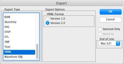
following export options are supported:
VRML Format
Specifies the format version to use for export.
VRML 2.0 Texture Support
This file format now supports texture export
Wavefront OBJ
Wavefront OBJ is widely used when dealing with graphics technology. This file format allows you to export colors, names, texture coordinates, and normals. Exporting texture coordinates is particularly useful for producing smooth renderings by preserving the original NURB.
Batch
The Batch File command located on the File menu will read in a variety of file formats and process into other file formats.
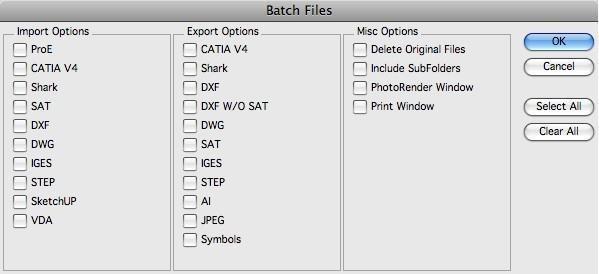
Misc Options
| Delete Original Files | Deletes the files after it is processed (use with caution). |
|---|---|
| Include SubFolders | Process files located in nested subfolders. |
| PhotoRender Window | Photorenders the contents of the window. |
| Print Window | Prints the screen. |
*Web Publish*
****The Web Publish command is located under the File menu. The tool will capture the screen and embed the resulting JPEG within an HTML file suitable for display within an internet browser application.
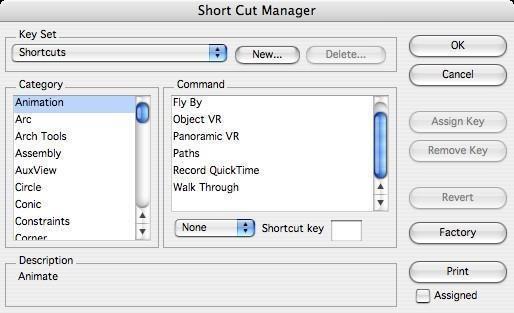
Short Cuts
Shortcut keys provide access to creating and modifying user defined command keys. Multiple shortcut key sets can be defined. These key sets can be used in support of multiple users sharing a common workstation or multiple design modes. The shortcut key dialog manager displays a list of commands and allows the designer to assign associated keys.
As you become more proficient with Punch! Shark, you may elect to use the shortcut keys to issue commands. Shortcut keys require less mouse movements to access frequently used commands, but require that the user memorize command keys or position a “cheat” sheet nearby. This chapter describes features for accessing capability through the typical Apple character prefix and special SharCAD keys.
Key Set
Used to activate the current key set.
New…
Click this button to input a name for a new key set.
Delete…
Click this button to delete an existing, user-defined new key set. The system-defined “Shortcuts” key set cannot be deleted.
Category
This section lists the available command groups.
Command
This section lists the available commands within the selected category. Any existing shortcut assignments are also indicated in this list.
Shortcut key
Displays the shortcut key for the selected command list item. Also used to change or assign a shortcut to the selected command list item.
Description
A brief description of the selected command list item.
Assign Key
Assigns the specified shortcut key to the selected command list item. Any existing shortcut for this command is removed.
Remove Key
Removes the specified shortcut key from the selected command list item.
Revert
Changes the keys back to the point where the dialog box was first displayed.
Factory
Changes the current shortcut key set assignments back to the original installation values.
Prints a listing of all keys and their assigned keys.
Assigned
If checked, only the shortcut keys that are assigned to commands are printed. If not checked, all keys are printed.