Modify
The Modify Tools menu provides commands for editing or repairing geometry such as curves, surfaces, or solids.
• Repair Profile
• Simplify Profile
• Create Outline
• Remove Duplicate Entities
• Remove Zero Length Curves
• Convert to Spline Surface
• Simplify Solid
• Part Repair
• Solid Divide
• Thread
Repair Profile
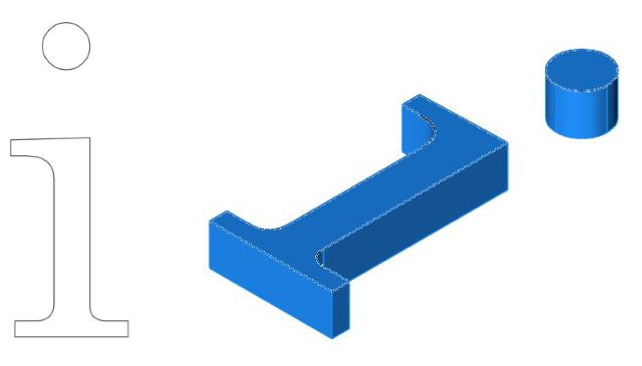
The Repair Profile command examines and repairs the following common issues with a closed collection of curves.
Small Overlaps
Small Gaps
Non-Planar curves
Example 1:
- Select the Repair Profile command.
- Select the curves in a profile to repair.
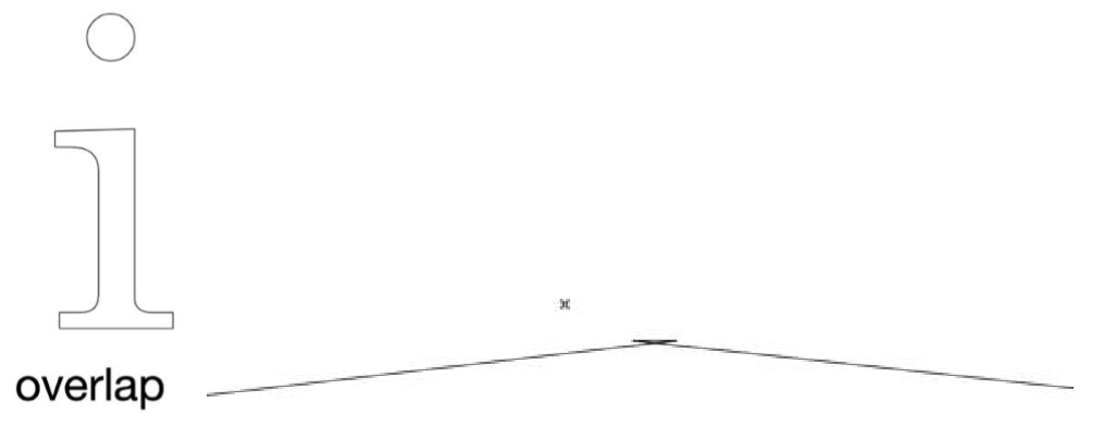
- Overlap issue detected and repaired. The Profile is then suitable for profile-based operations such as extrude into a solid.
Example 2:
- Select the Repair Profile command
- Select the curves in a profile to repair
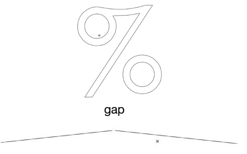
- Gap issue detected and repaired. The Profile is then suitable for profile-based operations such as extrude into a solid.
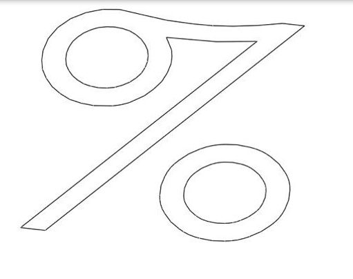

Simplify Profile
The Simplify Profile command converts lines/polylines into simplified line, arcs, circles, and splines.
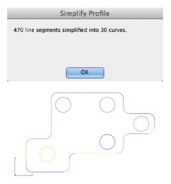
Example 1:
- Select the lines in the profile to simplify.
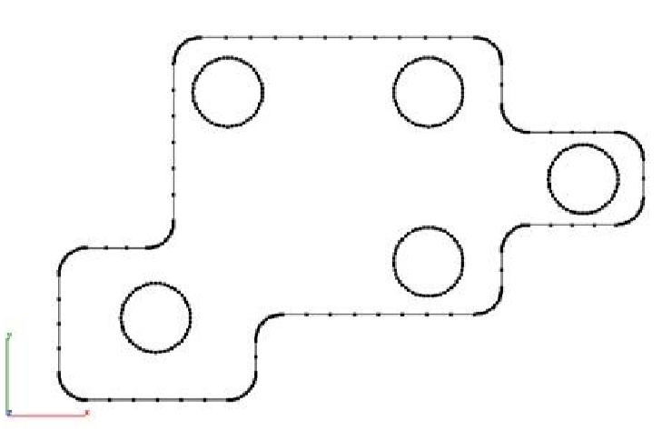
- Dialog is displayed showing the results. In this example, 470 lines are converted into 17 arcs and 13 lines.
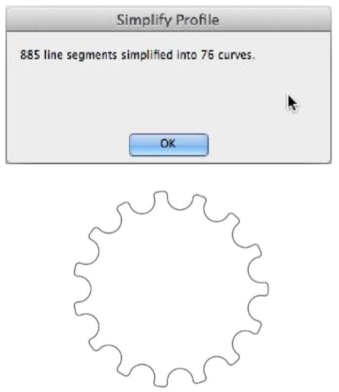
Example 2:
- Select the lines in the profile to simplify.
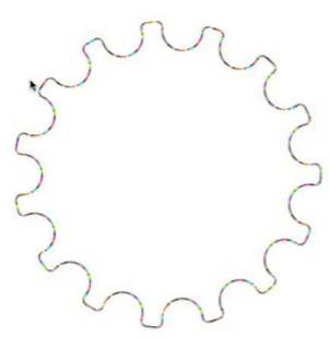
- Dialog is displayed showing the results. In this example, 885 lines are converted into 45 arcs and 31 lines.
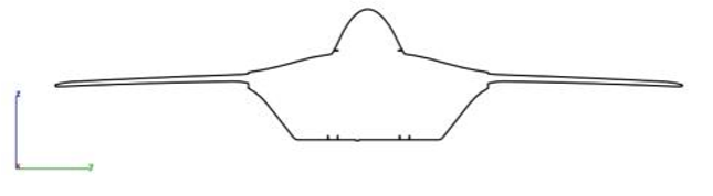
Create Outline
The Create Outlines tool takes a group of selected curves and finds the outline relative to the current Work Plan.
Example:
- Select the Create Outlines command.
- Set the WorkPlane for the outline.
- Select the curves for the outline command.
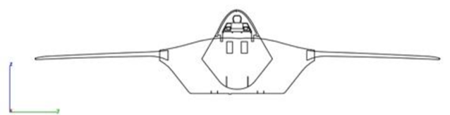
- Curves are trimmed or removed from the original selection set to correspond to the profile outline.
Remove Duplicates
The Remove Duplicates command examines curves and solids for duplicate representations.
Example:
- Select the Remove Duplicates command.
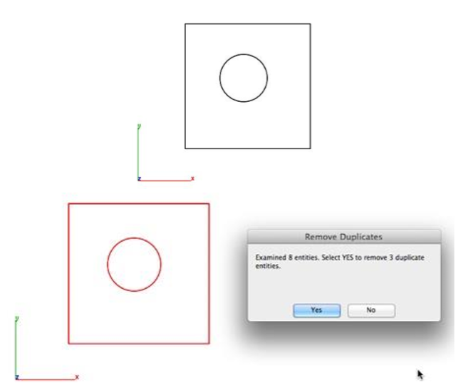
- Select the objects to check for duplicates.
- Select Yes to remove the duplicates. Selecting No leaves the duplicates within the drawing file.
Remove Zero Length Curves
The Remove Zero Length Curves commands delete curves below a specified length and radius.
Example:
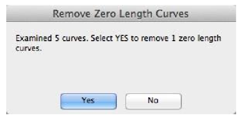
- Select the Remove Zero Length Curves tool.
- Set the tolerance value for smallest length and radius.
- Select the curves to check for lengths and radius.
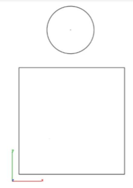
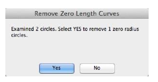
- Select Yes to remove small length curves.
- Select Yes to remove small radius curves.
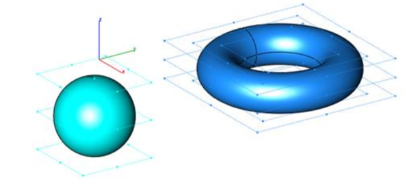
Convert to Spline Surface
The Convert to Spline Surface tool changes analytic faces to NURBs providing access to control vertices.
Example:
- Select the Convert To Spline Surface.
- Select the objects to convert.
- Illustration with converted spline surfaces and Show Points enabled.
Simplify Solid
The Simplify Solid tool converts NURB into analytic face. The following operations are performed as part of simplification.
Replacement of small sliver faces
Merge similar neighboring faces
Convert NURB faces into planar, cylinder, and cone.
Clean the body of unnecessary edges
Example:
- Select the Simplify Solid tool.
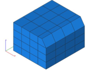
- Select the part to simplify.
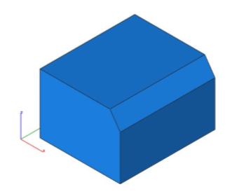
- Results from simplify.
Part Repair
Attempts to repair a part using alternate stitching, repair, and translator technology.
Example:
- Select the surface or solid to repair.
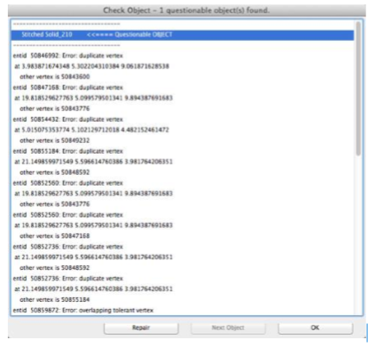
- Select the Part Repair tool. The Part is repaired if possible.
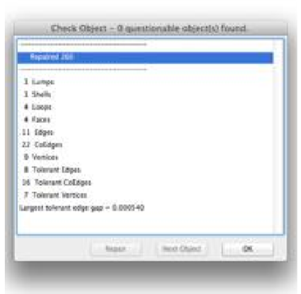
- Select the surface or solid to repair. Repaired part is created as separate object from the original. Verify Check Object confirms part is now repaired.
Solid Divide
This tool is used to create or obtain intersection between two solids. This will divide the two solids from their intersecting points. Created solid (intersection part) can be taken apart after performing this process.
Example
- A Select Solid divide tool from PowerPack > Modify
- Select any two solids which are intersecting
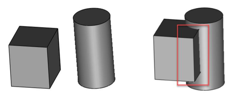
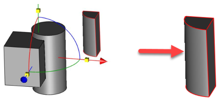
- After the command executes, we get a new solid which is actually an intersection part of two solids.
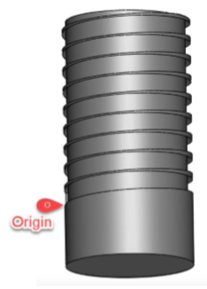
Thread
This tool adds a threaded section to any cylindrical surface, externally or internally.
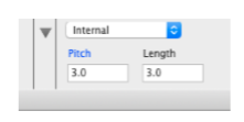
Fields that are available to achieve custom thread are:
Length: Sets the total length of the thread.
Pitch: Set the distance between the ridges on the thread.
Type: External / Internal
Example
- Select Thread tool from PowerPack > Modify and enter Length, Pitch values
- Select cylindrical solid face to add thread

- Specify thread origin point from where threads will start.
At the end, the result will be as below