Utilities
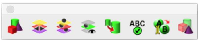
The Utilities menu provides tools for a variety of entity management operations such as Assorted Colors, Preview Layers, Auto Layer, Isolate Layer, Change Scale, Spell Check, Rename, and Show by Name.
Assorted Colors
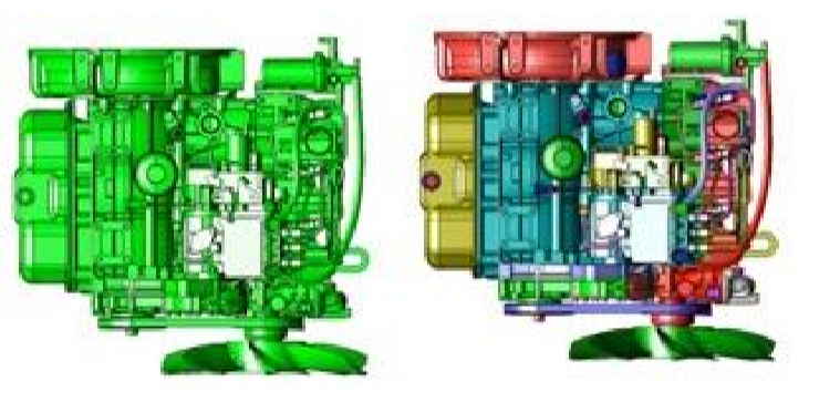
The Assorted Colors tool assigns up to 20 colors per group of entities selected. The tool is useful for visually identifying individual parts such as a file import.
Example 1: Assorted Colors
1.Select Assorted Colors tool from the PowerPack menu.
- Select entities to apply Assorted colors.
- Entities colors updated.
•
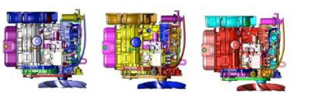
Example 2: Assorted Colors
- Select Assorted Colors tool from the PowerPack menu.
- Select entities to apply Assorted colors.
- Select entities to apply Assorted colors.
- Select entities to apply Assorted colors.
Repeatedly using on a set of entities will offset the start color for each selection, providing alternative color arrangements.
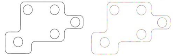
Example 3: Assorted Colors
- Select Assorted Colors tool from the PowerPack menu.
- Select curves to apply Assorted colors.
The tool is also useful for visually identifying individual curves in a profile.
AutoLayer.
AutoLayer is a tool that will automatically assign an entity to a layer based on same shape or by entity name. Use AutoLayer to help organize files imported from other applications that do not support layers.
By Name
Creates a new layer for each of the selected entities and uses the entity name for the layer. If the name is shared, each entity is put into the same layer.
By Same Shape
Creates a new layer for entities that have the same shape. Entities with the same shape are placed in the common layer. Shape comparisons data include volume, area, length, width, height.
Tip: Use the Separate all Parts if the imported file contains one mesh.
Example 1: By Name
- Import an obj file that contains named elements.
- Select Auto Layer from PowerPack.
- Select all entities in the drawing.
- Each entity is assigned a layer where the layer name is the entity name.
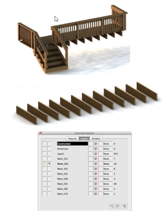
Example 2: By Same Shape
- Import an STL file that contains mesh elements with same shapes.
- Select Auto Layer from PowerPack.
- Select all entities in the drawing.
- New layers are created and populated with same shapes.
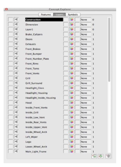
Preview Layers
The Preview Layers utility provides a user interface to rapidly step through the layers. The play button will animate through the layer start and end region. The step forward and backward buttons manually provide control through the layers.
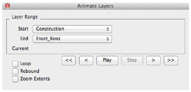
Start: The starting layer to animate
End: The ending layer to animate
Loop: Continue to animate once the end layer is reached with the Start layer.
Rebound: Continue to animate once the end layer is reached with the End layer.
Zoom Extents: For each layer, zoom extents before the repaint.
Play Start the animation display.
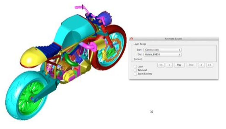
Example: Preview Layers
1.Select Preview Layers tool from the PowerPack menu.
Change File Units/Scale
There are many file formats that do not contain unit settings that include STL, OBJ, PLY, 3DS, and older DXF files. The Change File Units command allows you to quickly change a file scale based on Units or Scale Factor.
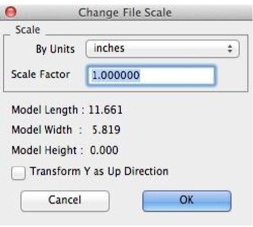
By Units: Determines the scale factor by converting between units.
Scale Factor: Specify the scale factor by typing in a value in the edit control.
Model Length/Model Width/Model Height: Shows the model size if the Scale Factor is applied to the current drawing
Transform Y as Up Direction: Rotates the model about the x-axis 90 degrees.
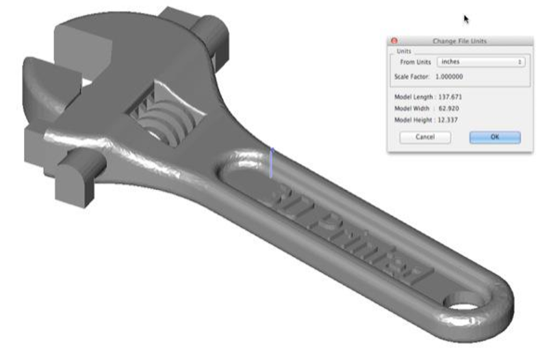
Example 1: Change
File Scale In the example below, an STL file is imported into the application where inches are the default units but the file was created in millimeters. The Change File Units dialog box shows the model extents to be 137x63x12 inches, which is not consistent with an actual wrench. By setting the From Units to millimeters, the wrench is scaled to the correct size.
- Select the Change File Scale option from the PowerPack set of tools.
- Select Millimeters from the Units pull down.
- Select OK.
- Each entity in the file is scaled by the Scale Factor.
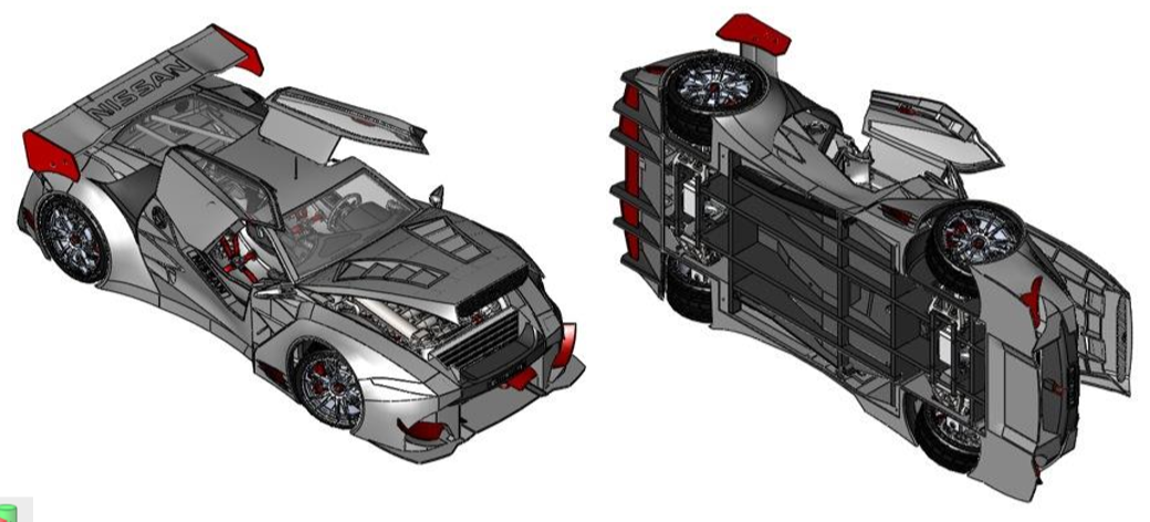
Example 2: Change File Scale
In Another feature of the Change File Scale command is the ability to swap y and z. For example, in the file below, the model is transformed using the Transform Y as Up
Direction option.
- Select the Change File Scale option from the PowerPack set of tools.
- Select the Transform Y as Up Direction option.
- Select OK.
- Each entity in the file is rotated such that y is now z.
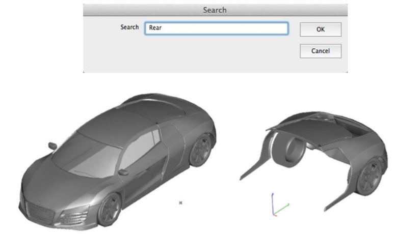
Show Only by Name
The Show Only by Name tool displays just the entity with the provided name. This tool changes the Show/Hide flags of the entity.
Example: Show Only By Name
- Select Show Only By Name tool from the PowerPack menu.
- In the Search dialog box, type in the string to search.
- All entities with the string specified are displayed only In the example below all entries that include the string "Rear" are displayed. In the example illustrated below, fourteen objects are displayed.
Rename
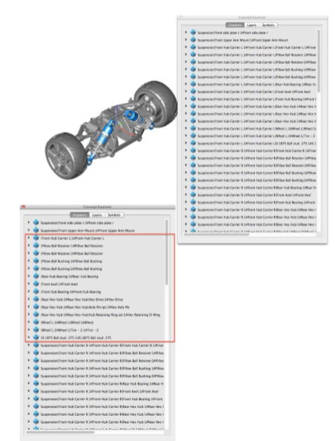
The Rename tool provides a way to rename a large number of entities. This tool is especially useful for renaming entities imported from external applications. For example, Inventor attaches the full assembly representation to the part name. Renaming supports two methods:
Search and Replace:
Entity names containing the Search string are replaced with the Replace string.
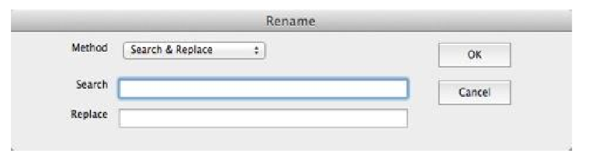
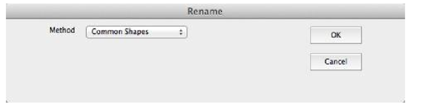
Common Shapes:
All entities sharing the same geometric shape are renamed to the same name. This is especially useful for creating Bill of Materials.
Example: Rename
- Select Rename tool from the PowerPack menu.
- In the Rename dialog box, type in the string to rename.
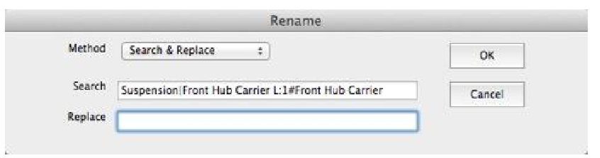
- Click Ok to rename all entities.
Spell Check
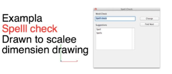
The Spell Check examines all visible text for possible misspellings and provides suggestions.
Example: Spell Check
- Select the Spell Check option from the PowerPack set of tools.
- Each entity with potential spelling errors is displayed in the Word Check field.
- Select Change to update to the Suggested value.
- Select Find Next to proceed to the next entity.
Isolate Layer from Selection
Sets the display and work layer from the selected objects.
Example: Isolate Layer
- Select the Isolate Layer option from the PowerPack set of tools.
- Select an object.
- The display and contraction layers are updated to the selected object.