Floor Plan Tab
By beginning with QuickStart, walls of each room are automatically generated. Customize your floor plan by adding doors, windows, stairs, and other components to begin your plan design. Punch! Home Design Software makes creating the final home plan of your dreams, exactly as you want it, simple.
You can define your wall thickness, before placing, and create custom-sized walls in a snap. Further customize your design by adding windows, doors, stairs, cabinets, and so on.
Drawing Walls
QuickStart makes it easy to begin your design process, but you can add or delete walls at any time. You can either draw “freeform” or to specific dimensions, based on your needs and your design. Wall segments are automatically joined when you draw, and are placed at right angles, while curved walls and bay walls include angular segments.
You can draw the followings types of walls:
- Straight Wall
- Curved Wall
- Bay Wall
Below are some references that may be helpful as you design:
- Wall Properties
- 2D Editing Methods
- Reshaping and Resizing 2D Objects
- Changing Segment Length
- Customizing Wall Framing Properties
- Breaking a Wall
Straight Wall
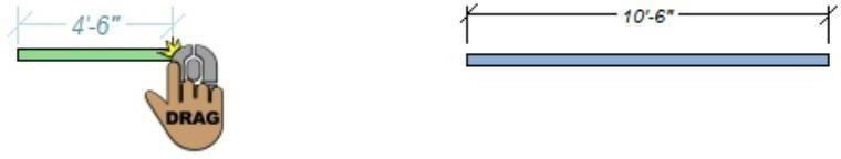
There are two ways to draw straight wall segments: freeform or custom length.
The Wall Tool creates a straight, freeform wall segment. The angle and length are determined by the start and end points of the wall you draw.
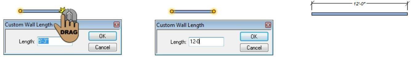
The Wall (Custom Length) Tool creates a straight wall segment based on a custom defined length that you specify. The angle is determined by the start and end points of the wall you draw, and the length is based on the values you specify in the Custom Wall Length dialog box.
To draw freeform straight walls 
-
On the Floor plan toolbar, click the Wall Tool from the Walls toolset.
-
Use the Click-and-Drag drawing method to drag the wall segments to the desired length and angle.
To draw custom length walls 
-
On the Floor plan toolbar, click the Wall (Custom Length) Tool from the Walls toolset.
-
Use the Click-and-Drag drawing method to drag the wall segment to the desired angle. The Custom Wall Length dialog box is displayed when you release the mouse button.
-
Type the Length you want in the text box and click OK.
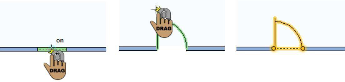
Curved Wall 
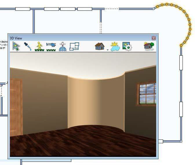
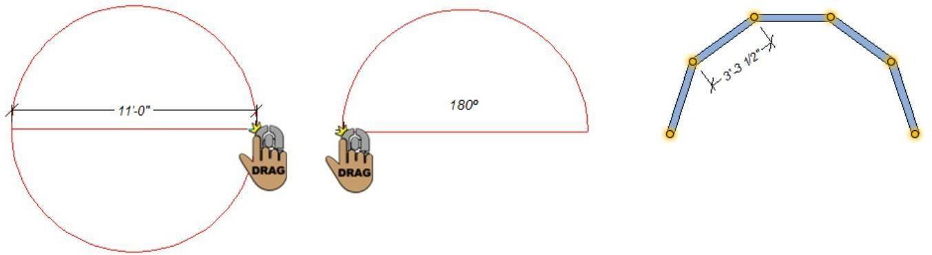
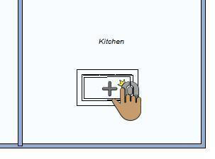
The Curved Wall Tool creates a curved wall based on a diameter and angle you define. The default length for each segment in the curve is 3'-6", but you can change this on the Properties tab, in the Curved Seg. Length text box, before you draw.
In the example to the right, a curved wall has been added in the kitchen. The curved segment length used to create this curved wall was 1'-0".
To draw a curved wall
-
On the Floor plan toolbar, click the Curved Wall Tool from the Curved wall toolset.
-
On the design window, press the mouse button and drag to define the wall length. A rubber band line appears and follows the pointer. This line signifies the diameter of your curved wall.
-
Release the mouse button when the wall is the correct length and then drag the mouse clockwise, or counter-clockwise, until the wall is the shape or angle you want.
Note: Press SHIFT to reverse the arc direction and flip the curved side.
4. Click to place the wall.
Bay Wall
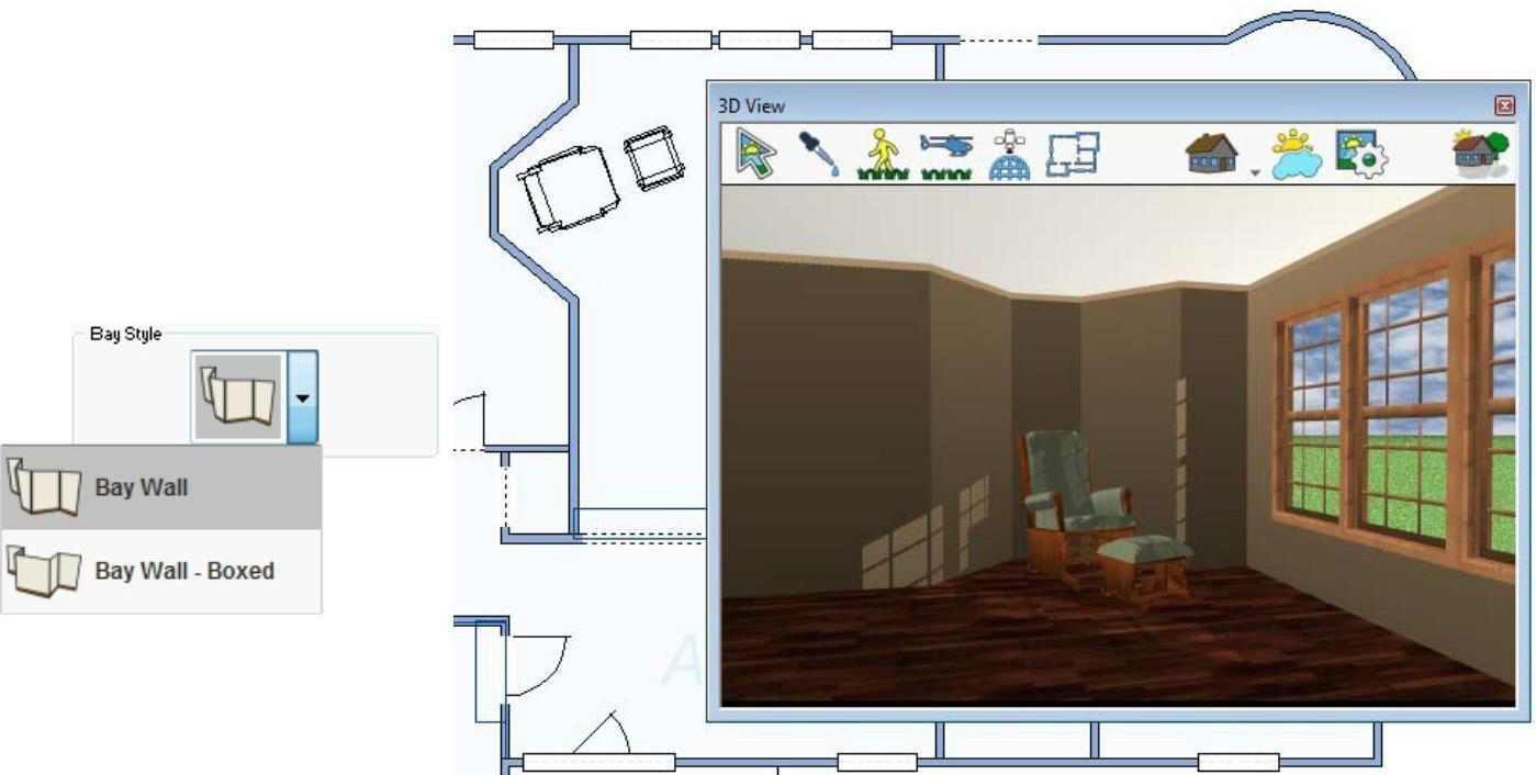
The Bay Wall Tool creates an angular or prependicular bay section along an existing wall. You can choose between an angular or prependicular style before you draw using the Bay Style button on the properties tab. Once placed, the bay style cannot be changed.
Note: As wall attachments, the width of the bay wall must be equal to or less than the length of the wall segment you're attaching to.
To draw a bay wall 
- On the Floor plan toolbar, click the Bay Wall Tool from the Curved wall toolset.
- On the Properties tab, click the Bay Style button and choose the style you want.
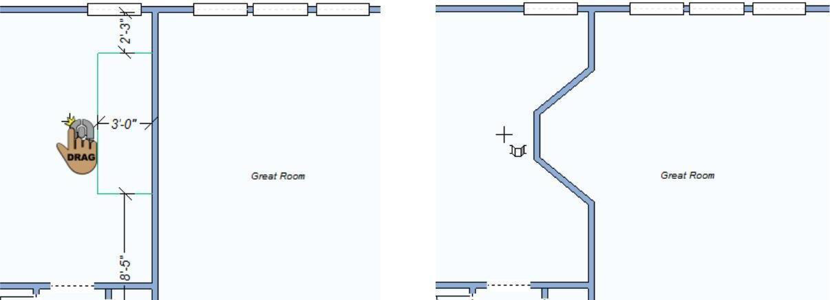
- Use the Drag Along Wall draw method to place an angular or perpendicular bay section along an existing wall.
Wall Properties
Once you have drawn walls for your design, you have the option to customize many features. From wall thickness, floor height, and stud spacing to automatic flooring options, you have alternatives for almost every feature.
Note: Always press the ENTER to accept new values in a text box.
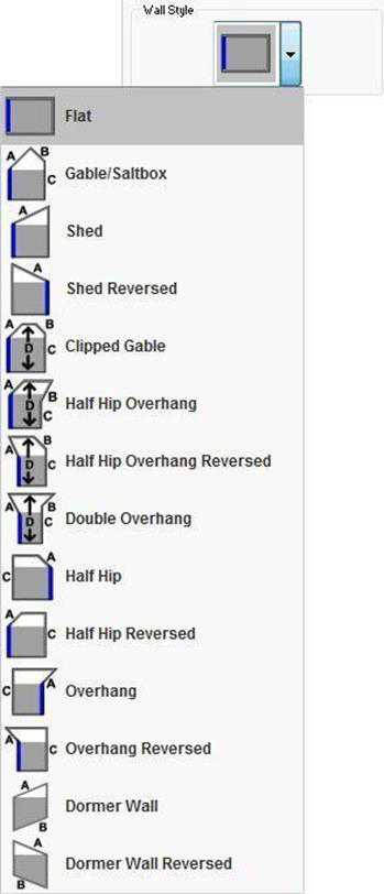
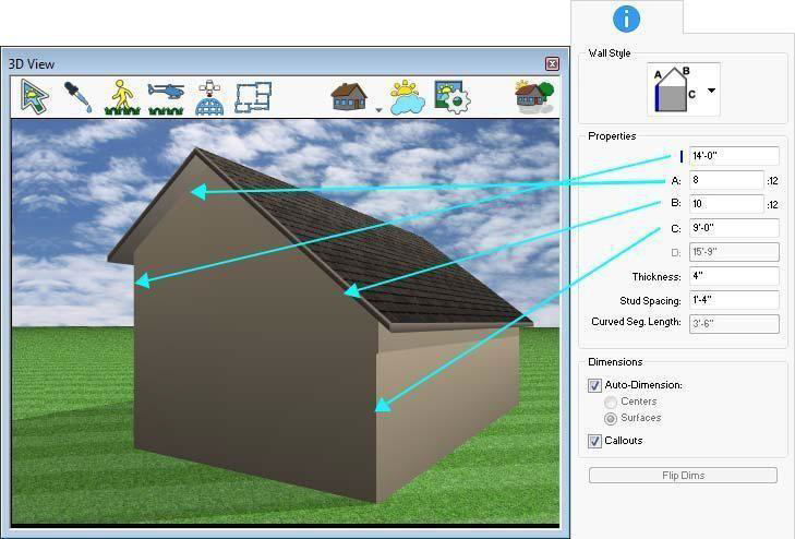
- Wall Style button allows you to choose from a variety of wall styles, including irregular shapes, gable style, and many more. Wall styles are available to accommodate different types of roofs.
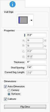
- Wall Height corresponds to the blue height line in the wall style icon. Editing this value adjusts the corresponding wall segment.
- Additional Segment Heights and Pitches are available depending on the wall style. For walls that use multiple height and pitch settings, edit the values that correspond to the segment in the wall style icon.
- Thickness defines the width of the lumber used for framing the wall. The higher the thickness, the wider the stud boards.
- Stud Spacing defines the distance between each stud board in the wall framing.
- Curved Segment Length (applies to curved walls only) defines the length of each segment in the curved wall. Edits to this value must occur before the wall is drawn.
- Auto-Dimensions checkbox controls the display of dimensions on individual wall segments. Select the checkbox to enable; deselect to disable. When enabled, you can choose to measure walls from their surfaces or centers.
Note: If automatic dimensioning is off for the entire application, this setting does not enable dimensions. For more information, see “Dimensioning”, which begins on page 57.
- Callouts checkbox controls the display of dimensions for windows and doors on the selected wall segment. Select the checkbox to enable; deselect to disable.
- Flip Dims button controls which side of the wall the dimensions are displayed.
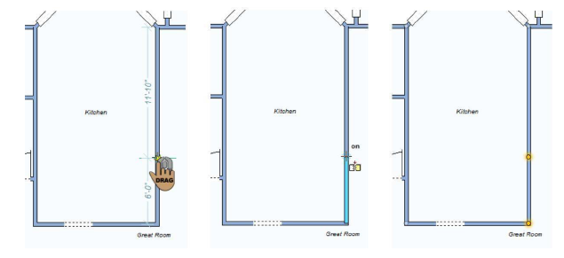
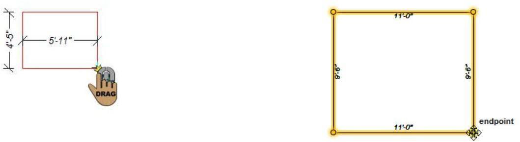
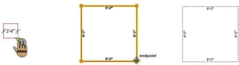
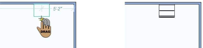
Changing Segment Length
Straight line segments such as walls, fences, floors, and more can be resized easily to adjust one of the ends of the segment or both ends. Not only can you change the length of a segment, but you can also move an adjoining segment with the segment.
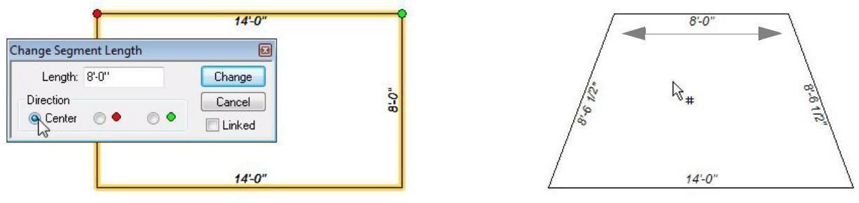
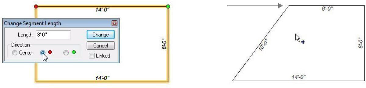
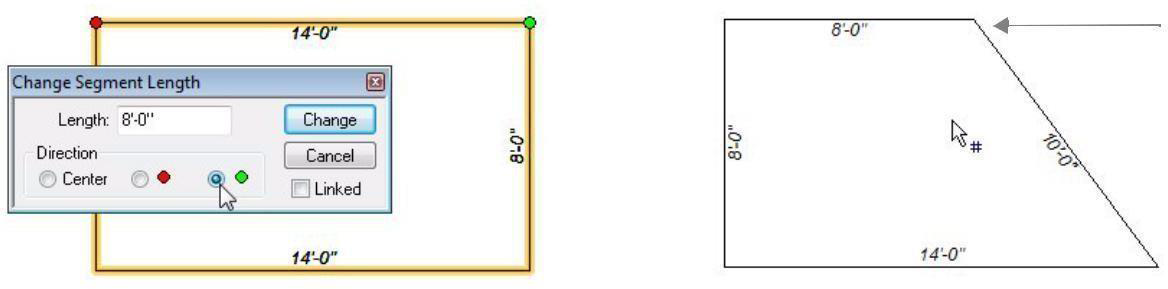
The Change Segment Length dialog box include a red point and a green point that correspond to end points on the selected segment. The point you choose is the side that is resized. You can also choose to resize from center. Note: You may need to manually adjust end points to fine tune their position.
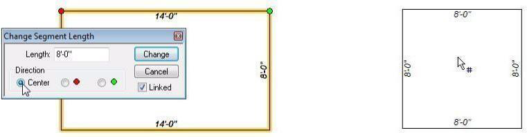
- Resize segment from Center > segment is resized to the specified length by adjusting the segment from its center.
- Resize segment from Point (red)> segment is resized to the specified length by adjusting the red point.
- Resize segment from Point (green)> segment is resized to the specified length by adjusting the green point.
When the Linked checkbox is selected, the adjoining walls remain perpendicular and are “linked” to the resized segment. In the example below, the top segment is resized to 8'-0" and the Linked checkbox is selected, so the adjoined segments move with it.
To change the wall segment length 
-
On the Edit Toolbar, click the Resize Segment (Custom Length) Tool.
-
Click to select a line segment. The Change Segment Length dialog box is displayed.
-
Select the end point from which you want to resize the segment or choose Center to resize the segment from its center.
(optional) Uncheck the Linked box if you want the wall to be resized, but do not want the adjoining wall to remain perpendicular to it.
- Type the new length in inches or feet and inches, separated by a hyphen and then click Change. The wall segment is resized.
For example, when Ft-In units are enabled, 10-0 indicates ten feet, while 10 is interpreted as ten inches.
Automatic Flooring
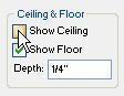
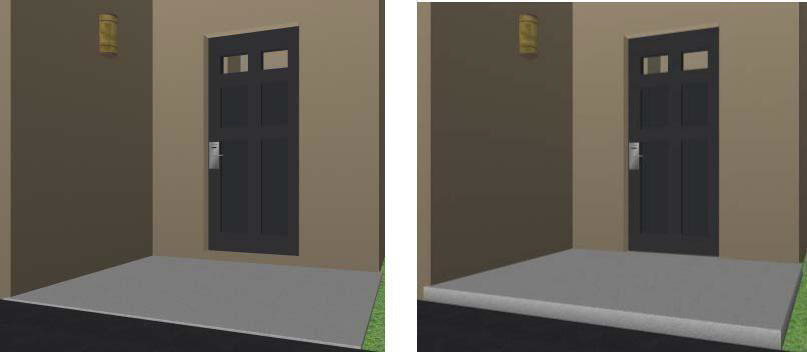
By default, enclosed walls are drawn with a 1/2" auto-floor. You can turn the auto-floor on or off on the Properties tab, as well adjust its depth.
After removing the auto-floor, you can manually draw a floor. For more information, see “Adding and Removing Flooring”.
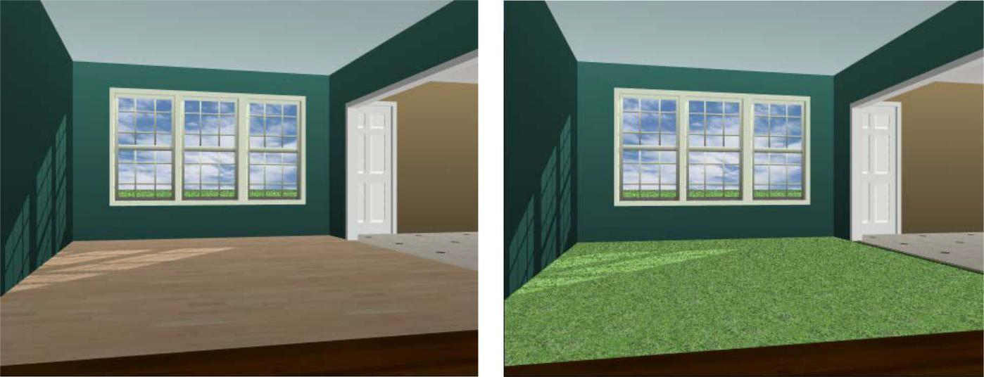
Auto-Floor On Auto-Floor Off
To control the auto-floor in a room
-
Click inside an enclosed room to select it. Its properties are displayed on the Properties tab. (Press the SHIFT key as you click to select more than one room.)
-
On the Properties tab, click to select the Show Floor checkbox to turn on the auto- floor. Deselect the Show Floor checkbox to turn off the auto-floor.
To change an auto-floor depth
-
Click inside an enclosed room to select it. Its properties are displayed on the Properties tab. (Press the SHIFT key as you click to select more than one room.)
-
On the Properties tab, click to select the Show Floor checkbox to turn on the auto-floor and then type the depth you want in the corresponding text box, then press the ENTER key. The auto-floor is updated.
Automatic Ceiling
By default, enclosed walls are drawn with an auto-ceiling. You can turn the auto-ceiling on or off on the Properties tab.
After removing the auto-ceiling, you can use the Floor Tool to create a manually drawn ceiling. For more information, see “Automatic Flooring”.
Auto-Ceiling On Auto-Ceiling Off
To remove the ceiling over a room
-
On the Edit Toolbar, click the Selection Tool and click inside an enclosed room. Its properties are displayed on the Properties tab. (Press the SHIFT key as you click to select more than one room.)
-
Click to deselect the Show Ceiling checkbox. The ceiling is removed from the selected room.
To replace the ceiling over a room, reselect the Show Ceiling checkbox
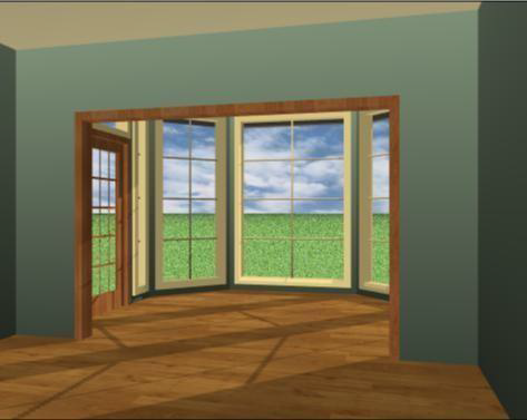
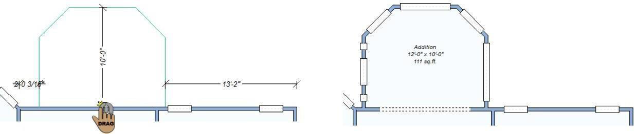
Placing a Room Addition
Using the Room Addition Tool, you can add space to your design with just two mouse clicks. Quickly add space then edit the room along with the rest of your design, or customize the room addition settings first, and then place a complete room that is ready for finishing touches. Room additions are wall attachments, so they must be placed along an existing wall.
- Room Addition Settings
Before placing a room addition, you can customize the settings or edit the addition components like you would other components in your drawing.
Walls tab
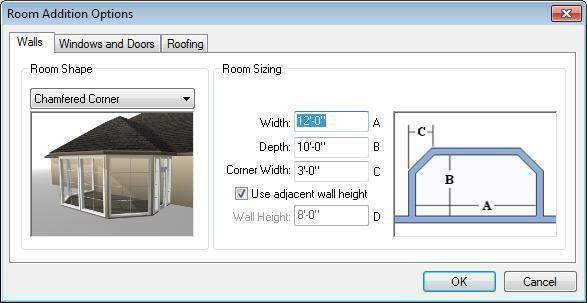
- Room Shape Choose between rectangular or chamfered corner walls.
- Room Sizing The text boxes correspond to the letters in the diagram. When the Use Adjacent Wall Height checkbox is selected, the room addition walls inherit the height of the wall where it is attached. To specify a different room addition wall height, deselect the checkbox.
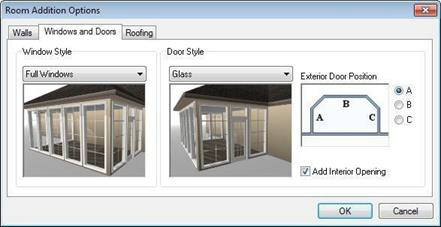
Windows and Doors tab
- Window Style Choose which style windows are placed on the walls (none, full-size, 3/4, or fill the walls with windows).
- Door Style Choose which style exterior door is included, if any.
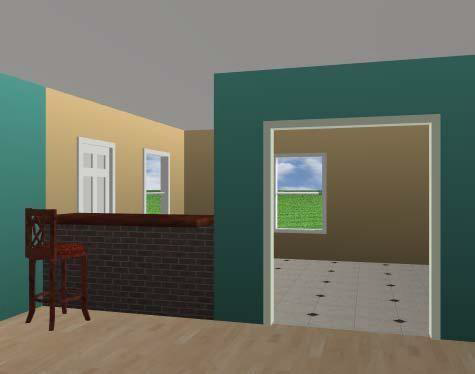
Exterior Door Choose the location of the exterior door. The radio buttons correspond to the letters in the diagram. You can also choose to include an interior opening by selecting the Add Interior Opening checkbox. This creates a cased opening leading to the addition.
Roofing tab
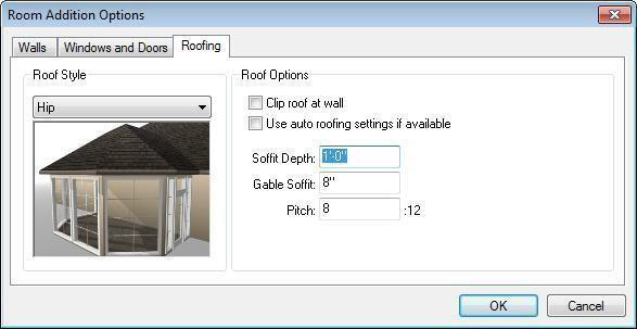
- Roof Style Choose the roof style for the addition (none, flat, hip).
- Roof Options The following options are available:
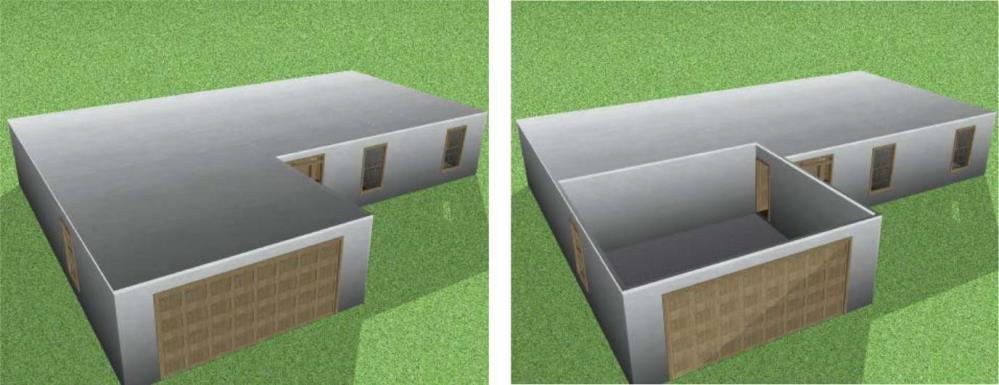
- The Clip Roof at Wall checkbox allows you to stop the roof where the room addition attaches to the wall. This is useful when the anchoring wall is part of a multi-floor design where the roof is not at the same level as the addition’s roof. When this option is deselected, the addition’s roof extends into the roof like a hip connector.
- Select the Use auto roofing settings if available checkbox to use the automatic roof settings that have been set. For information on auto-roofs, see “Auto-Roof Properties”, on page 183.
- Type the Soffit Depth, Gable Soffit, and Pitch you want in the corresponding text boxes. Below are some references that may be helpful as you design:
- Reshaping and Resizing 2D Objects
- Door Properties
- Window Properties
- Roof Properties
To place a room addition 
- On the Floor plan toolbar, click the Room Addition Tool.
(optional) On the Properties tab, click the Options button and edit the walls, windows, door, or roof settings, and then click OK to close the dialog box.
- Using the Drag Along Wall drawing method, drag along a wall and release on the side of the wall where you want the addition placed.
Breaking a Wall
With Punch! Home Design Software, it’s easy it easy to fine tune your rooms, adding an inset, for example.
Breaking walls is useful for removing a wall section or creating separate surfaces for applying different colors and materials. When a wall includes a break, you can select the segments separately to delete, reshape, or resize the wall segments. When a color, material, or trim is applied to a segment, it is applied to only one segment.
In the example to the right, a wall break was used to break a single wall segment and then resize one of the new segments to create a half way between two room.
Below are some references that may be helpful as you design:
- Reshaping and Resizing 2D Objects
- Wall PropertiesApplying Trims
- Applying Paint and Color
To insert a wall break 
1- On the Floor plan toolbar, click the Wall Break Tool. 2- Use the Drag Along Wall drawing method to place the break and create two wall segments.
Adding Doors and Openings
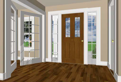
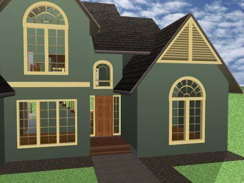
All doors and cased openings are automatically dimensioned to neighboring walls, doors, and windows. There are three types of openings and nine door styles available, as well as two additional style libraries, and they are all placed in the same way.
You can add cased openings with or without curvature, interior and exterior doors, as well as glass doors and sliding doors. After a door is added, you can easily convert it to a double door and edit the size and other properties. Additionally, there’s a stylized panel doors library and a custom door library.
Door styles are described in “Door Properties”. All of the door styles behave the same way.
Below are some references that may be helpful as you design:
- Door Properties
- Applying Building Materials & Applying Paint and Color
- Applying Trims
- Component Description
To add a door 
1. On the Floor plan toolbar, click the Door Tool.
2. Use the Drag Along Wall drawing method to position the door and release to place.
- Drag to a side of the wall to define the door swing direction and then click to place the door.
Door Properties
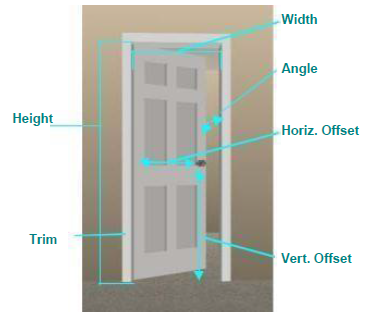
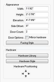
Doors are defined by their width, height, elevation, and trim size. You can edit the properties before you draw or after the component has been added to your design by selecting it and clicking the Properties tab.
Note: Always press the ENTER to accept new values in a text box.
- Door drop-down menu allows you to switch between the Doors properties and the Door Hardware properties. When Doors is selected, its styles and properties are displayed.
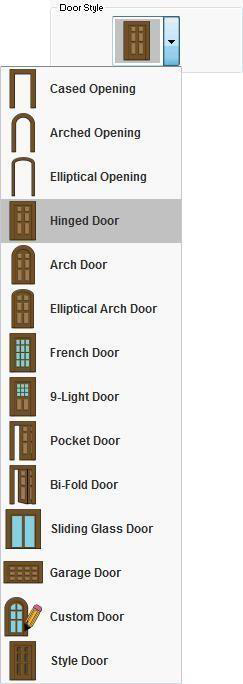
- Door Style drop-down menu provides access to a variety of door styles.
Note: When choosing a door style for subsequent doors, be sure none of the doors in your design are selected. Otherwise the new style and properties are applied to the selection.
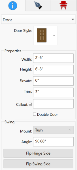
- Width defines the distance from one side of the door opening to the other. You can change the width by typing a value or by dragging an end point on the door to the width you want.
- Height defines the distance from the bottom of the door opening to the top.
- Elevate defines the distance between the auto floor elevation and the bottom of the door.
- Trim Size defines the width of the trim around the door. This is not included in the overall height.
- Callout Allows you to add custom labels to door. For example text identifying specified models from a manufacturer.
- Double Door checkbox allows you to convert the selected door to a double door. The existing properties stay the same so you may want to edit the width to create two full-sized doors. This is not available for curved door, sliding door, or garage door styles.
- Mount drop-down menu allows you to choose if the door is positioned in the center of the door casing or is positioned flush to the side where the hinges are positioned.
- Angle defines the angle the door (or doors) is opened (0 closes the door).
- Flip Hinge Side button flips the side of the door that the door hinge is on.
- Flip Swing Side button controls if the door swings inward or outward.
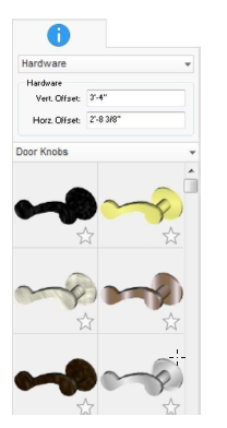
- Hardware drop-down menu allows you to switch between the Doors properties and the Hardware properties. When Door Hardware is selected, its properties and libraries are displayed.
- Vert. Offset defines the vertical position of the hardware relative to the bottom of the door.
- Horiz. Offset defines the horizontal position of the hardware relative to the hinges.
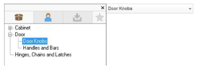
- Libraries are available for Door Knobs and Handles and Bars. When you select a style in the Preview Bar, the hardware is applied to the selected door.
Each library includes a Remove Hardware style which, when selected, removes the hardware from the selected door.
Adding Windows
Like doors and cased openings, there are an extensive variety of windows available in Punch! Home Design Software. They are automatically dimensioned to neighboring walls, doors, and other windows. There are a number of window styles available in Punch! Home Design Software as well as a custom library, and they are all placed in the same manner.
You can combine windows side-by-side or stacked to create almost any configuration or place custom style windows. Window styles are described in “Window Properties”. Choose the window style before or after you place the window.
Below are some references that may be helpful as you design:
- Window Properties
- Elevating Objects
- Applying Paint and Color
- Applying Trims
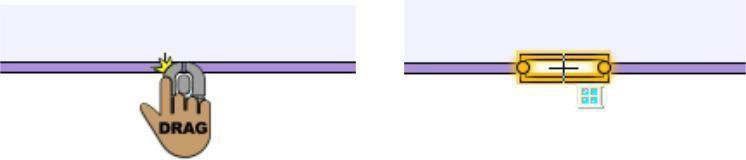
To add a window 
- On the Floor plan toolbar, click the Window Tool.
- Use the Drag Along Wall drawing method to position the component on wall where you want it and release to place.
Window Properties
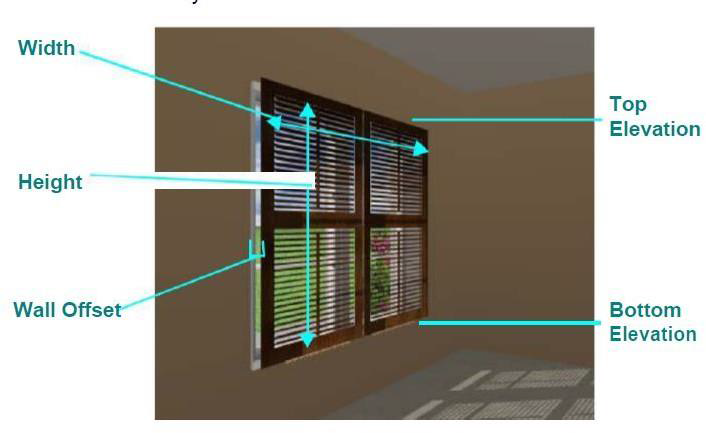
Once windows have been placed, it is easy to resize them. You can do this by specifying exact dimensions, or by dragging one end, until you have the required size. You can also control the height, elevation and trim size. Some of the window styles offer pitch and the ability to flip them vertically or horizontally to create beautiful groupings to suit any room design.
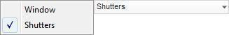
Shutters are a property of windows that you can quickly add and edit. Shutters include a lot of customizable options so you can set the exact layout (whether the shutters are on either side of the window or over the opening), size, position, style, and more. To add or edit window shutters, select the window (or windows) and choose Shutters from the Window properties drop-down menu.
Note: Always press the ENTER to accept new values in a text box.
Window
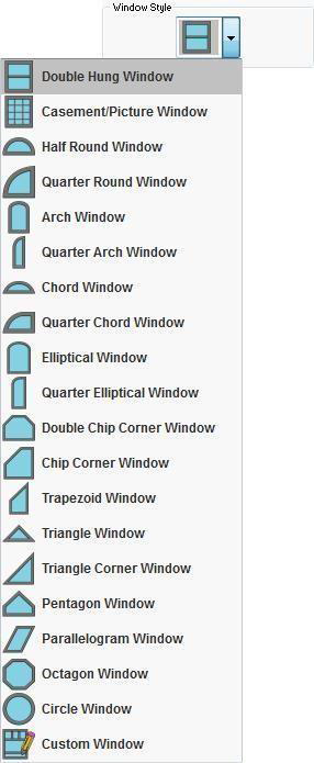
- Window Style drop-down menu provides access to a variety of window styles.
Note: When choosing a window style for subsequent windows, be sure none of the windows in your design are selected. Otherwise the new style and properties are applied to the selection.
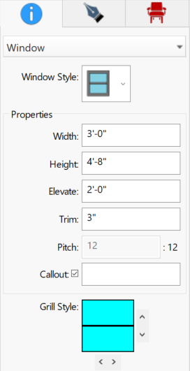
- Width defines the width of the window opening. You can change the width by typing a value or by dragging an end point on the window to the width you want.
- Height defines the height of the window opening.
- Elevate defines the distance from the floor that the window is positioned.
- Trim Size defines the width of the trim around the window. This is not included in the overall height.
- Pitch defines the slope of window styles that include angles. The higher the pitch the more severe the slope.
- Callout Allows you to add custom labels to windows. For example text identifying specified models from a manufacturer.
- Grill Style defines the number of horizontal and vertical grills exist for double hung and casement windows.
- Flip buttons allows you to change the orientation of non-symmetrical windows.
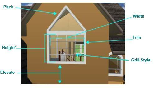
Two windows are used in this example. The height of the bottom window only is called out; the top window has a separate height.
Shutters
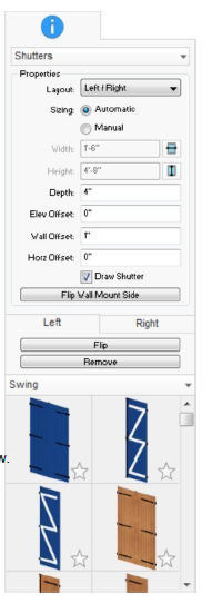
- Layout drop-down lets you choose if the shutters will be positioned on either side of the window opening or as a single unit inside the window opening.
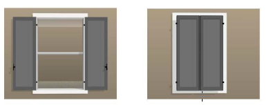
Left/Right Single
- Sizing options lets you choose Automatic to automatically size the shutters to the selected window or choose Manual and enter a custom width and height. When Manual is selected, you can click the AutoSize buttons to automatically resize based on the window dimensions.
- Depth controls the thickness of the shutter. The more the depth increases, the further the shutter projects out from the window.
- Elev Offset controls the distance the shutter is offset vertically from the window base.
- Wall Offset controls the distance the shutter is offset from the wall. Some shutters styles include hardware facing the wall, in this case the hardware is offset by this value.
- Horiz Offset controls the distance the shutter is offset horizontally along window.
- Flip Wall Mount Side button controls which side of the wall the shutter is mounted on.
- Shutters libraries allow you to choose the shutter style you want for the window. You can choose from the Stock Libraries or the User Library, where you can add your own shutters. For more information on the User Library, see “Organizing Library Content”.
Shutters are applied based on the Layout you have selected. When the Left/Right layout is selected, the Left and Right tabs are available. In this layout, shutters are added to each side individually, so choose the shutter style you want for the left and right sides.
- Flip button controls the shutter style. You can flip the design for each shutter.
- Remove button removes the shutter.
Placing a Staircase
As you create more than one floor in your design, you’ll want to draw a staircase. Straight staircases and curved staircases are drawn using the ceiling height, unless you specify a different height on the Properties tab before drawing the staircase. The center line defines the direction and path of the staircase, while the staircase height value defines the distance to the top of the staircase.
To create an opening for the stairway in the upper floor, see “Adding and Removing Flooring”.
After you’ve drawn your staircase, you can apply different colors and materials to the steps, railing spindles, posts, and handrails.
You can draw the followings types of staircases:
- Straight Stairway
- Curved Stairway
Below are some references that may be helpful as you design:
- Staircase Properties
- 2D Editing Methods
- Reshaping and Resizing 2D Objects
- Customizing Staircase Framing Properties
- Applying Paint and Color & Applying Building Materials
Straight Stairway
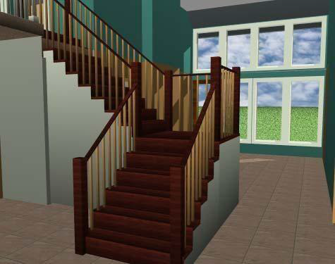
You can draw a staircase along a straight line or add multiple points to create an L-shaped or U-shaped staircase with landings. You can add as many points as you’d like to customize the shape of the staircase, however the overall height is controlled by the height property value. The number of steps in the staircase depends on the overall height of the staircase as well as the step height and depth.
Note: After a staircase if drawn you can reverse the direction by right-clicking the center line and choosing Reverse Staircase Direction.
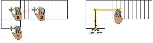
To draw a straight stairway 
- On the Floor plan toolbar, click the Straight Stairway Tool from the Staircase toolset.
- In the design window, click to set the start point and drag in the direction you want the stairs to rise, then click again to set the next point.
- Continue to click points and drag to define the shape of the stairway and then right click to place.
Curved Stairway
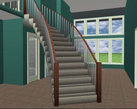
Curved staircases are a single segment that curve in the direction you draw. The number of steps depends on the overall height of the staircase as well as the step height and depth.
Note: After a staircase if drawn you can reverse the direction by right-clicking the center line and choosing Reverse Staircase Direction.
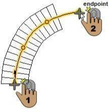
To draw a curved stairway 
-
On the Floor plan toolbar, click the Curved Stairway Tool from the Staircase toolset.
-
Click to set the start point and drag to set the curve in the direction you want the stairs to rise, then click and again to set the end point and place the staircase.
Note: Hold down the SHIFT key while drawing to constrain the staircase to a perfect arc.
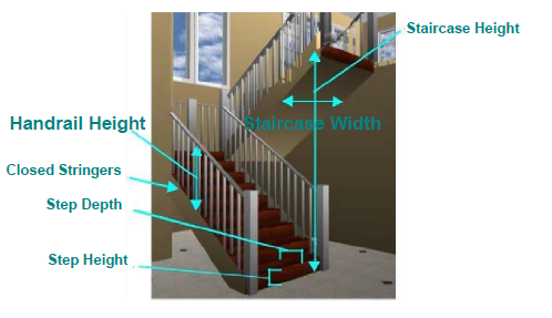
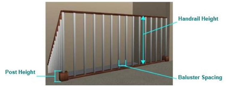
Staircase Properties
Once you have drawn a staircase, you can modify features and location to suit your needs. With Punch! Home Design Software you have control over stairway height, width, riser, and tread dimensions, handrail height and placement, and whether the stairs are open or enclosed.
Note: Always press the ENTER to accept new values in a text box.
- Staircase Height defines the distance from the base of the staircase to the top step.
- Staircase Width defines the distance from one side of the staircase to the other side.
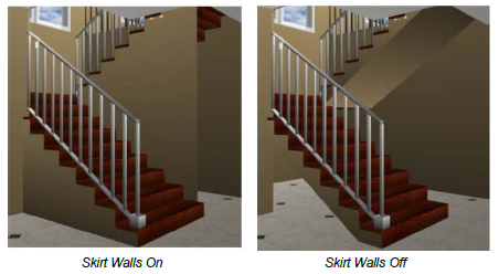
- Skirt Walls checkbox controls the display of the alonside the staircase. When slected, the walls are enabled; when deselected they are disabled.
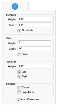
- Step Height defines the height of the step risers.
- Step Depth defines the depth of the stair treads.
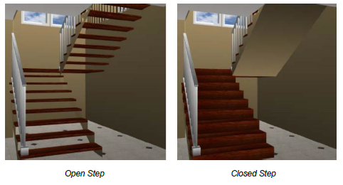
- Open checkbox controls if step risers are included. When selected, risers are excluded; when deselected they are included.
Handrails Height defines the distance from the bottom of the handrail to the top.
Left and Right checkboxes control the display of the left and right handrails. When selected, the handrail is enabled; when deselected it is disabled.
Closed Stringers checkbox controls whether the stringer is closed along the side of the staircase or open. When selected, the full stringer is closed along the side of the staircase; when deselected the stringer is cut open with each step.
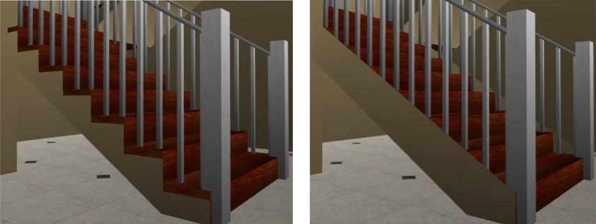
Open Stringer Closed Stringer
- Large Base checkbox controls the size of the base of the stringer. When selected, a large base is enabled; when deselected it is disabled.
- Auto-Dimension checkbox controls the displays of dimensions in 2D. If automatic dimensions are not displayed for the entire drawing, the stair dimensions are not displayed. For details on controlling the automatic dimensions display “Dimensioning”
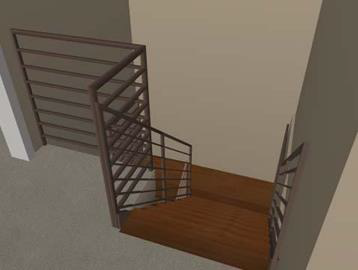
Adding Railings
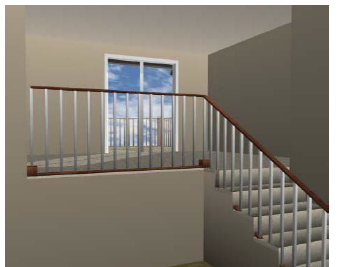
Using the Straight Railing or Curved Railing tool, you can add railings to create a barrier around floor openings or other edges where unequal elevations exist. You can add railings around floor cutouts, at the top of a staircase, around raised floor sections, or any other place in your design
The shape and configuration of railings can be customized, and you can apply different materials to the rail, post, and balusters. You can specify the railing height and baluster spacing before or after drawing on the Properties tab. As you draw a railing, each point you click as you draw creates a post. Below are some references that may be helpful.
- Railing Properties
- 2D Editing Methods
- Reshaping and Resizing 2D Objects
- Elevating Objects
- Applying Paint and Color & Applying Building Materials
To draw a railing 
-
On the Floor plan toolbar, click the Railing Tool.
-
On the Properties tab, click the Draw Method drop-down menu and choose the shape you want.
-
Use the Define 2D Shape drawing method to draw a railing.
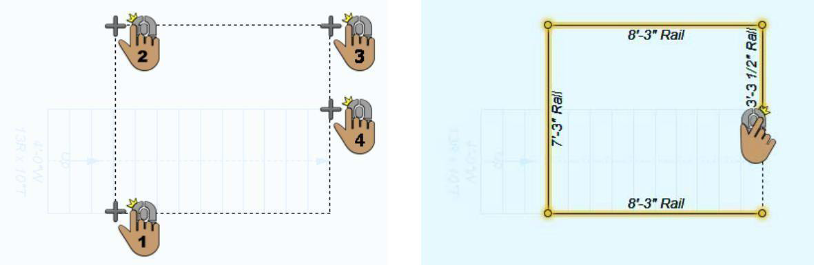
This example shows a railing drawn using the Open Polygon shape
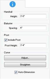
Railing Properties
Railings are defined by their height, baluster, and post settings. After a railing has been added to your design, you can edit its properties by selecting the railing and clicking the Properties tab. Below are the available railing properties.
Note: Always press the ENTER key to accept new values in a text box.
- Handrail Height defines the distance from the bottom of the handrail to the top
- Baluster Spacing defines the distance between each baluster, or spindle.
- Include Post checkbox controls if posts are included at each point you clicked when drawing the rail. When selected, posts are included; when deselected they are excluded. You can add or remove individual posts using the Add Point and Remove Point Tools. For more information, see “Editing Detail Shapes”.
- Post Height defines the height of the posts. You can select individual posts and edit their height or double-click the rail to select all posts and then edit the height so they match.
- Curve options control curvature. For more information, see “Changing Curve Tension”.
- Auto-Dimension checkbox controls the displays of dimensions in 2D. If automatic dimensions are not displayed for the entire drawing, the stair dimensions are not displayed. For details on controlling the automatic dimensions display “Dimensioning”.
Adding and Removing Flooring
You can manually draw a floor section that exists independent of an existing floor or surface. This enables you to customize the shape, thickness, and surface material to create a unique floor section.
You can also remove flooring by defining a cutout area. This works for floors drawing using the Floor Tool as well as auto-floors created within enclosures.
The following options are available:
- Floor Tool
- Floor Cutout Tool
Below are some references that may be helpful as you design:
- Floor Properties
- Reshaping and Resizing 2D Objects
- Elevating Objects
- Component Description
- Applying Building Materials
Floor Tool 
You can use floor sections in place of an auto-floor, for raised areas in a room, to create ceilings for patios or porches, or for other situations that call for an adjustable surface.
To draw flooring
-
On the Floor Plan tab, click the Floor Tool from the Floor toolset.
-
On the Properties tab, click the Draw Method drop-down menu and choose the shape you want.
-
Use the Define 2D Shape drawing method to draw a floor section.
This example shows a floor drawn using the Rectangle from Corner shape
Floor Cutout Tool 
You can easily design lofts, creative staircase openings, create an opening where one does not currently exist.
To draw a floor cutout
-
On the Floor Plan tab, click the Floor Cutout Tool on the Floor toolset.
-
On the Properties tab, click the Draw Method drop-down menu and choose the shape you want.
-
Use the Define 2D Shape drawing method to draw a floor cutout section.
This example shows a floor cutout drawn using the Square From Center shape
Floor Properties
Once a floor or cutout section has been added to your drawing, you can access flooring properties on the Properties tab.

Note: Always press the ENTER key to accept new values in a text box.
- Flooring Thickness defines the distance from the bottom of the floor section to the top.
Thickness 1" Thickness 4"
- Curve options control curvature. For more information, see “Changing Curve Tension”.
- Auto-Dimension checkbox controls the displays of dimensions in 2D. If automatic dimensions are not displayed for the entire drawing, the floor dimensions are not displayed. For details on controlling the automatic dimensions display “Dimensioning”.
- Calculate Area button automatically calculates the square footage of the floor section. The area is displayed on the Properties tab.
Adding Accessories
You can easily add drapes, curtains, blinds, and more to any window or door. Accessories are designed to “track the walls”, meaning they can only be placed on wall segments and will move with those walls.
There are a number of libraries available with different styles of accessories.
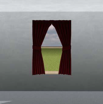
When the tool is active, you can choose the style you want and then place the accessory, or you can drag-and-drop a different style onto the accessory in the 3D view. For more information on the Wall Accessories library, see “Wall Accessories Library”.
Once placed, you can automatically resize the accessory to match a window size.
Below are some references that may be helpful as you design:
To add accessories 
- On the Floor Plan tab, click the Wall Accessories Tool.
- Select the accessory you want to place and then use the Drag Along Wall drawing method to place the accessory.
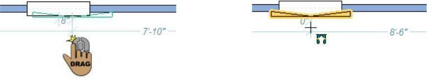
Wall Accessory Properties
Wall Accessories width, height, elevation, and how far they are offset from the wall. You can also adjust their translucency to create a sheer effect. After an accessory has been added to your design, you can edit its properties in the Properties tab by selecting the accessory. Below are the available properties.
Note: Always press the ENTER to accept new values in a text box.
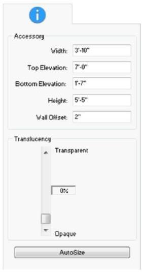
- Accessory Width defines the overall distance from one side of the accessory to the other side.
- Top Elevation defines the elevation of the top of the accessory. Accessories are positioned vertically based on their elevation, so when you edit this value it affects the overall elevation of the accessory.
-
Bottom Elevation defines the elevation of the bottom of the accessory. Accessories are positioned vertically based on their elevation, so when you edit this value it affects the overall elevation of the accessory.
-
Accessory Height defines the overall distance from the top of the accessory to the bottom.
- Wall Offset defines the distance between the wall and the accessory.
- Translucency slider controls the opacity of the accessory. For a sheerer look, increase the transparency.
- AutoSize resizes an accessory to match the dimensions of a particular window or door. To autosize an accessory, click to select it, click the AutoSize button, and then select the window. The accessory is automatically fit to the dimensions of that window.
Adding Cabinets
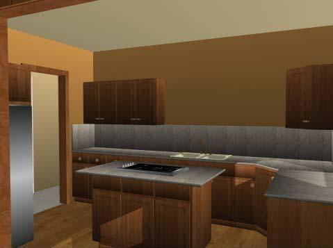
Cabinets can be added to your design with just a few mouse clicks. In addition to placing pre- designed cabinets, you can customize each feature as well as create a cabinet of your own from scratch. There are many cabinet styles available and each cabinet’s dimensions are customizable.
When the tool is active you can choose the cabinet style you want from the Properties tab. You can also change the cabinet style after it has been placed in your drawing Cabinet styles are described in Cabinet Properties.
Below are some references that may be helpful as you design:
- Cabinet Properties
- Applying Paint and Color
- Applying Building Materials
To add cabinets 
- On the Floor Plan tab, click the Cabinet Tool.
(optional) On the Properties tab, click the Cabinet Style button and choose the style of cabinet you want.
- Use the Drag Along Wall drawing method to position the component on the side of a wall where you want it and release to place.

To add an island 
-
On the Floor Plan tab, click the Cabinet Tool.
-
Use the Click Once to Place drawing method to place the island.
Cabinet Properties
You can easily edit a cabinet after you’ve placed it in your drawing. From resizing base doors to adding additional drawers, each aspect of a cabinet is customizable. To access the different faces and components of a cabinet, click the cabinet Component button on the Properties tab, as described below.
Cabinet Styles
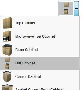
The available properties depend on the active cabinet style. You can choose the cabinet style before you place a cabinet or after by selecting the cabinet in your design.
Cabinet Components
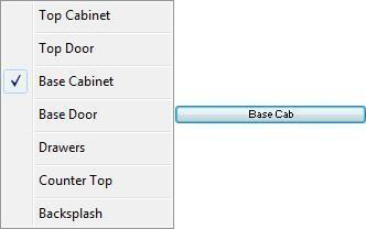
The Component button lists the components on the active cabinet style that are available for editing. When you choose one of the components, its properties are displayed on the Properties tab.
The cabinet components that are available for editing depending on the active cabinet style. For example, the Full Cabinet style includes Top Cabinet and Top Door components, while the Base Cabinet style does not. Each of the available Component properties are described below.
Note: Always press the ENTER to accept new values in a text box.
Top Cabinet
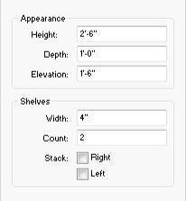
- Height defines the height of the overall height of the top cabinet component. Note: The width of the top cabinet is controlled by the base cabinet.
- Depth defines the distance from the front of the cabinet to the wall.
- Elevation defines the distance between the counter top and the base of the top cabinet.
- Shelves Width defines how wide the shelves are. The overall width of the top cabinet is determined by the base cabinet, so when the shelves width is adjusted, it affects the width of the top cabinet space.
- Count defines the number of shelves that exist.
- Stack Right add Stack Left checkboxes control if the shelves are included and
- stacked on one or both sides of the top cabinet. When selected, shelves are included; when deselected they are excluded.
Top Door/Base Door/Drawers
Note: The size of components is limited to the available space on the cabinet surface. If you enter a value that is larger than the available space, the maximum size is used by default.
After updating a size, you may have to adjust the component position.
- Width defines the distance from one side of an individual door or drawer to the other side.
- Height defines the distance from the bottom of an individual door or drawer to the top.
- Elevation defines the distance between the bottom of cabinet and the base of the component.
- Side Offset defines the distance that the component is positioned from the side of the cabinet.
- Count defines the number of doors or drawers.
- Stack Doors/Stack Drawers checkbox controls whether base cabinet doors and drawers are position side-by-side or stacked one on top of the other. When selected, the components are stack on top of each other; when deselected they are positioned side-by-side (available for Base Door and Drawers only).
- Mirror Hardware checkbox controls the position of the door hardware. When
- selected, all of the hardware is positioned at the same location on each door; when deselected the hardware is positioned in the top corner of the inside edge.
- Inset checkbox controls the display of the door or drawer. When selected, the component is inset as an opening; when deselected the door or drawer is displayed. (available for Base Door and Drawers only). Facing Style button provides style options for the door and drawer faces.
- Hardware Library button provides access to the Cabinet Knobs and Pulls libraries.
- Hardware Style button opens the hardware library styles. When a style is selected it is automatically applied to the hardware.
- Hardware Positioning allows you to click an arrow to move the hardware in that direction.
Base Cabinet
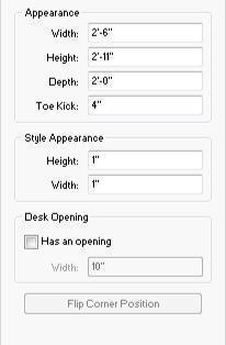
- Width defines the overall distance from one side of the cabinet to the other side.
- Height defines the distance from the bottom of the base cabinet to the top of the base cabinet.
- Depth defines the distance from the front of the cabinet to the wall.
- Toe Kick defines the height of the toe kick, measured up from the bottom of the cabinet.
- Style Height defines the distance between the top and bottom edges of the doors and drawers and the edges of the cabinet. When this value is adjusted, the size and position of the doors and drawers is affected.
- Style Width defines the distance between the side edges of the doors and drawers and the edges of the cabinet. When this value is adjusted, the size and position of the doors and drawers is affected.
- Desk Opening checkbox controls whether or not the cabinet includes an opening in the center. When selected, an opening is added, and you can adjust
- the Width in the corresponding text box. When deselected, an opening is not included.
- Flip Corner Position button flips the corner where the angled outward facing cabinet is positioned to the opposite corner (applies to corner style cabinets only).
Counter Top
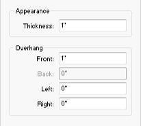
- Thickness defines the distance from the bottom of the counter top to the top.
- Overhang Front defines the distance the front edge of the counter top extends out from the cabinet.
- Overhang Back defines the distance the back edge of the counter top extends out from the cabinet (applies to island cabinets only).
- Overhang Left defines the distance the left edge of the counter top extends out from the cabinet.
- Overhang Right defines the distance the right edge of the counter top extends out from the cabinet.
Backsplash
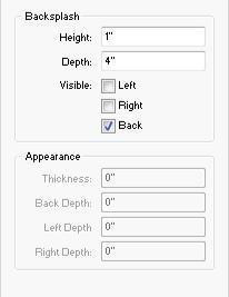
- Backsplash Height defines the distance backsplash extends up from the cabinet.
- Backsplash Depth defines the distance from the front of the backsplash to the wall.
- Left, Right, and Back Visible checkboxes control the visibility of the backsplash on that corresponding side. When selected, a backsplash is visible on that edge; when deselected it is not visible.
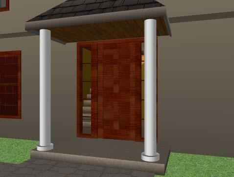
Adding Columns
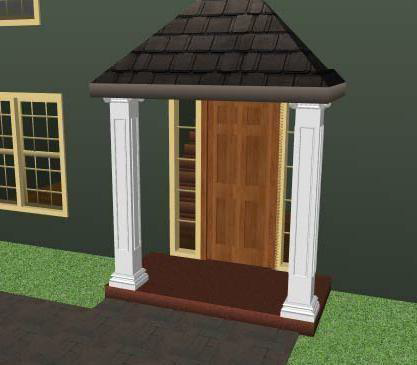
Columns can be added to your design for structural or decorative purposes.
Column are made up of three components, and you can customize the size and style of each. When placed in your drawing, the nearest ceiling height is detected and the column is drawn to that height.
Below are some references that may be helpful as you design:
- Column Properties
- 2D Editing Methods
- Elevating Objects
- Component DescriptionApplying Paint and Color & Applying Building Materials
To add a column 
-
On the Floor Plan tab, click the Column Tool.
-
Use the Click Once to Place drawing method to place the column in your design.

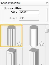
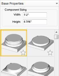
Column Properties
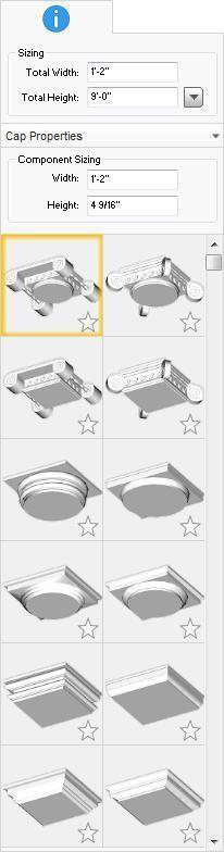
Columns are defined by their width, height, and the properties of their three components: Cap, Shaft, and Base. You can easily edit a column after you’ve placed it in your drawing. Note: Always press the ENTER to accept new values in a text box.
- Total Width defines the overall width of the entire column, including the base, shaft, and cap components.
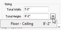
- Total Height defines the overall height of the entire column, including the base, shaft, and cap components. You can enter the height manually or, if there is a surface to which you want the column to extend, such as a ceiling or elevated floor section, you can choose that surface from the list of detected surfaces.
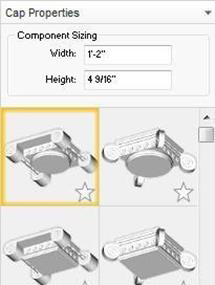
- Cap Properties includes the Width, Height, and Style for the column cap.
- Shaft Properties includes the Width and Style for the column shaft.
- Base Properties includes the Width, Height, and Style for the column base.
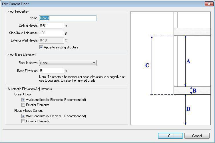
Editing Floor Properties
As you create your design, you may want to give a floor a unique name, change the ceiling height for an entire floor, or reorganize floors as you add more levels. You can edit a floor’s properties and maintain control over various floor levels at once or individually. The Edit Current Floor dialog box provides access to the floor properties, each corresponding to an area in the displayed diagram, so you can see what you are editing.
Note: When editing a floor, you must be working on that floor. For information on moving between floors, see “Work on Floor”.
Floor Properties
The Floor Properties control the overall wall height for the current floor, including the following settings that you can edit:
Name type a unique name for the floor. This is displayed in the Working Floor drop-down menu.
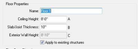
- Ceiling Height type the height you want in the Ceiling Height text box. Notice, the ceiling height affects the Exterior Wall Height value, which is the overall height of the wall.
- Slab/Joist Thickness type the slab or joist
- thickness you want in the corresponding text box. Notice, the value affects the Exterior Wall Height value, which is the overall height of the wall.
- Apply to existing structures checkbox applies the new ceiling height to the existing structures on this floor; deselecting this option applies the new ceiling height to subsequent structures only.
Floor Elevation
The Floor Base Elevation settings control the elevation of the floors. You can also control how existing elements are affected by elevation adjustments in the Automatic Elevation Adjustments section.
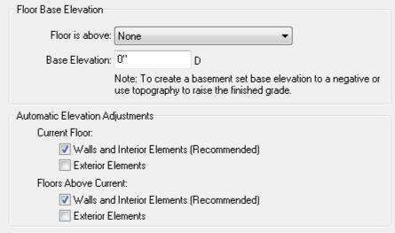
- Floor is above drop-down menu specifies the current floor’s vertical position in relation to other floors. To adjust a floor’s Base Elevation, the Floor is above setting must be None.
- Base Elevation defines the elevation of the floor base. A negative value results in below grade.
- Automatic Elevation Adjustments options specify whether or not you want the elevation adjustments to affect existing walls and interior elements, and exterior elements on the current floor and the floors above. When selected, the option is enabled.
Note: It is recommended that existing walls and interior elements are elevated automatically so they maintain the same elevation as the floor they are on.
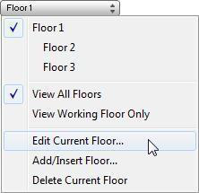
To edit floor properties
- Move to the floor you want to edit and then choose Edit Current Floor from the Working Floor drop-down menu. The Edit Current Floor dialog box is displayed.
- Edit the floor properties as needed and then click OK.
Adding and Deleting Floors
You can add up to 20 floor levels to your design, depending on your software program. Each floor can be associated with the elevation and ceiling height of the floor below it, or independent of the floor below it. When floor levels are stacked on top of each other, making their height and elevations relative ensures that each level is positioned at the correct elevation so walls and other elements are easily and accurately placed.
Adding Floors
The New Floor dialog box includes options for setting the floor height, elevation, and how elevation adjustments affect existing floors on upper levels.
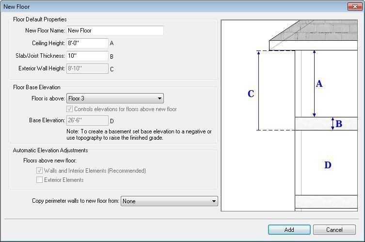
New Floor Name type a unique name for the floor. This is displayed in the Working Floor drop-down menu.
Note: A default floor name is automatically populated in the field, but each floor name must be unique so only one floor can use the default name.
- Ceiling Height type the height you want in the Ceiling Height text box. Notice, the ceiling height affects the Exterior Wall Height value, which is the overall height of the wall.
- Slab/Joist Thickness type the slab or joist thickness you want in the corresponding text box. Notice, the value affects the Exterior Wall Height value, which is the overall height of the wall.
- Floor is above drop-down menu specifies the new floor’s vertical position in relation to other floors.
- To add a new top floor, choose the current top-level floor.
- To insert between floors, choose the floor you want the new level to be above.
Note: When inserting a new floor, the Controls elevations for floors above new floor checkbox becomes active. When selected, the floors above the new floor are elevated based on the exterior wall height of the new floor. When deselected, the floors above the new floor are not repositioned.
- To add a new bottom floor, choose None.
Note: When None is selected, the Base Elevation text box becomes active. Type the elevation you want for the base floor.
Automatic Elevation Adjustments options specify whether or not you want the elevation adjustments to affect existing walls and interior elements, and exterior elements on the current floor and the floors above. When selected, the option is enabled. This option is only available when the Controls elevations for floors above new floor checkbox is selected.
Note: It is recommended that existing walls and interior elements are elevated automatically so they maintain the same elevation as the floor they are on.
- Copy perimeter walls to new floor from drop-down menu allows you to copy the perimeter walls from an existing floor level and draw them on your new floor level.
To add a new top floor or insert a new floor
-
Click the Working Floor drop-down menu and choose Add/Insert Floor. The New Floor dialog box is displayed.
-
Type a descriptive name in the New Floor Name text box.
-
Type the floor’s ceiling height and slab/joist thickness in the corresponding text boxes.
-
In the Floor Base Elevation section, click the Floor is above drop-down menu and choose the position you want for the new floor.
Set the elevation options as needed, depending on the position of the new floor level. (optional) If you want to copy the exterior walls from an existing floor to your new top floor, click the Copy perimeter walls to new floor from drop-down menu and choose from which floor the walls should be copied.
- Click Add to add the new floor level.
Deleting Floors
You can delete any of your existing floors, however at least one floor must remain. When you delete a floor, all of the floor’s contents are deleted with it.
To delete a floor
-
Click the Working Floor drop-down menu and choose the floor you want to delete.
-
Click the Working Floor drop-down menu again and then click Delete Current Floor. A confirmation window is displayed.
-
Click Yes to delete the floor. The floor and all of its contents are removed from your design.