Before You Draw in 3D
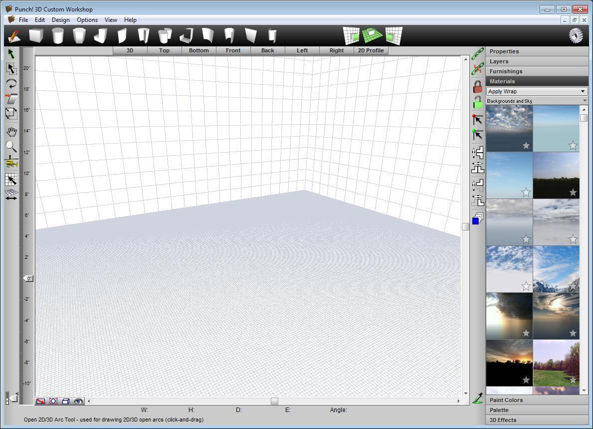
When you start 3D Custom Workshop, a new blank drawing grid is displayed with the floor grid active. The foreground and background colors are defined within 3D Custom Workshop. The unit of measurement (inches or metric) is defined in the home design program. If you start 3D Custom Workshop by double clicking an object in your home design program, that element is displayed on the design window.
If you are returning to work on an existing drawing, you must open to display it on the screen. Opening a file involves clicking Open on the File menu and specifying the name of the file you want to open. When you open a file, 3D Custom Workshop displays it in a new window.
The changes you make to an object occur only in your computer’s memory, until you save them. To preserve a drawing for later use, you must save it to a file. If you want to save a drawing, using its current name or if you want to save a new, untitled drawing, use Save. If you want to save a drawing with a new name, use Save As.
Opening Files and Objects
Opening a new file creates a new blank drawing grid with the floor grid active. You can open a saved Custom Workshop file at any time to further edit the design. Additionally, you can open 3D object from the Furnishings library to edit, save, or export.
To open a new file
- Click File menu > New (or press CTRL+N). An empty drawing grid is displayed.
Note: If you were working on an object, you will be prompted to save your work.
To open an existing file
-
Click File menu > Open (or press CTRL+O). The Open dialog box is displayed.
-
In the File Name box, type the name of the file you want to open or search for the file by browsing folders or drives.
-
Select the file you want and click Open.
To open 3D objects using drag-and-drop
-
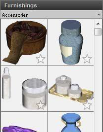
Click the Furnishings tab. The Preview Bar displays furnishing objects.
-
Click the Categories drop-down menu and choose the Library tab and category you want to view. Its contents are displayed in the Preview Bar.
Some of the categories are organized into sub-categories. Click to expand a category to see its contents. For more information on working with the content libraries, see “Organizing Library Content”.
- Scroll through the available objects in the Preview Bar and drag- and-drop the one you want to place onto the design window or 3D view window.
Saving a File
When you open a file, 3D Custom Workshop copies the file to your computer’s memory. As you work, you modify the copy stored in memory. Any system failure or loss of power destroys that copy. To save your work permanently, you must save it to a file on a disk. A good rule of thumb is to save every 15 minutes or after you’ve completed any work you wouldn’t want to redo.
When you click the Save command, 3D Custom Workshop saves the active drawing, using the name and location you last gave it. You can create more than one version of a drawing or save copies on another disk for safekeeping. You can save each version under a different name or you can save them under the same name in different folders or on different disks.
To save an existing file
- Click File menu > Save (or press CTRL+S).
To save a new, unnamed file
-
Click File menu > Save As. The Save As dialog box is displayed.
-
In the File Name text box, type a name and then click Save. 3D Custom Workshop automatically adds the POB extension.
Saving to a Content Library
In addition to saving your drawing file, you can save the object you’ve created or edited to one of the User Object Libraries or User Component Libraries.
The object libraries are available from the Furnishings tab in the main application. In order to save the object to an object User Library, the User Library must already exist. For more information on working with libraries, see “Organizing Library Content”.
The component libraries are available when select drawing tools are active; for example, when the Door Tool is active, a component library of door styles is available on the Properties tab.
To save an object to an object library
-
Click File menu > Save to Object Library or Save to Component Library. The Save to Library dialog box is displayed.
-
Choose the Object Library options and then click Save.
-
Library Location specifies the library where you want the object or component saved. The library you select is the library from which you can add the object or component to your design. Click the New button to create a new User Library folder. For more information on working with the content libraries, see “Organizing Library Content”.
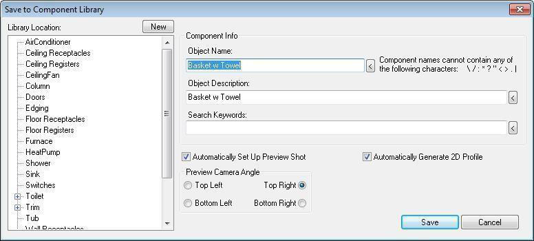
- Object Name is the name that appears in the Status Bar when you hover over the object in the Preview Bar.
- Object Description is the text describing the object. This appears in the Object Description dialog box.
- Keywords are the search terms that make the object easy to find when searching for objects. To view recently saved information, click the arrow button to the right of the text box.
- Ceiling mounted checkbox specifies that the object should be positioned on the ceiling surface. By default, objects are positioned on the floor surface (this applies to objects only).
- Automatically Generate 2D Profile checkbox controls if a 2D profile is automatically generated for the object. When selected, a simplified 2D profile is generated to make it easier when editing the 2D shape.
- Automatically Set Up Preview Shot checkbox, when enabled, automatically creates the preview that is displayed in the Preview Bar, regardless of the view orientation in 3D Custom Workshop. To create a custom preview based on the view in 3D Custom Workshop, deselect this option.
- Preview Camera Angle options specify the direction from which the object is displayed in the Preview Bar. Note: The object always appears on a light blue background.
Exporting Files
With 3D Custom Workshop, you can export your design drawing for editing or sharing, or you can export an image of your 3D design. When exporting a 3D image, the image is saved using the current rendering style (Textured, Wireframe, or ClearView modes).
To export a 3D rendering
- Click the Rendering Style button to toggle between Shaded and Wireframe.
(alternatively) Click View menu > 3D Rendering Style then click the rendering style you want.
-
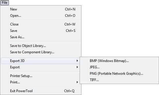
Click File menu > Export 3D, then choose the file format you want. The Export Image dialog box is displayed.
-
Choose the folder where you want the file saved.
-
In the File Name text box, type a name then click Save. 3D Custom Workshop automatically adds the file extension.
Note: The background of the file will be white, regardless of what color is specified in 3D Custom Workshop.
To export a 3D Custom Workshop drawing
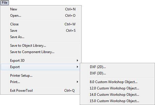
-
Click File menu > Export, then choose the file format you want. The Export Image dialog box is displayed.
-
Choose the folder where you want the file saved.
-
In the File Name text box, type a name then click Save. 3D Custom Workshop automatically adds the file extension.
Printing Objects
3D Custom Workshop prints using the current Windows printer. You can, however, print using any installed printer. Using the Print dialog box, you can specify a printer or plotter from those currently installed. Your object can be printed in Textured, Wireframe, or ClearView modes. In rendered mode, you have the choice of four qualities.
To print in Wireframe mode 
-
Click the Rendering Style button to specify Wire Frame. (alternatively) Click View menu > 3D Rendering Style > Wire Frame.
-
Click File menu > Print >
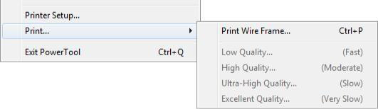
Print Wire Frame.
- In the Print dialog box, select the printer you want to use and click Print.
(optional) Change your printer and page preferences.
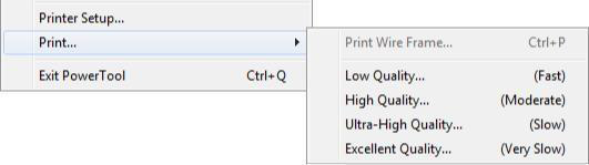
To print in rendered mode 
- Click the Rendering Style button to specify Shaded. (alternatively) Click View menu > 3D Rendering Style > Shaded View.
(optional) To print in Clear View mode, click View menu > 3D Rendering Style > Clear View.
-
Click File menu > Print, then click the Quality you want to use.
-
In the Print dialog box, select the printer you want to use and click OK.
(optional) Change your printer and page preferences.
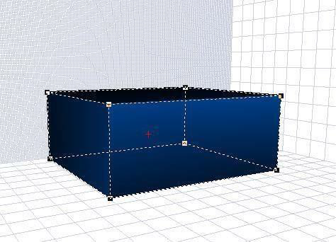
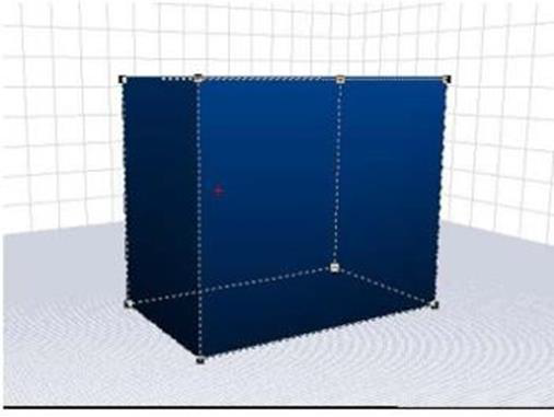
Drawing Grids
By using the Drawing Grids in 3D Custom Workshop, you can work on any object from three distinct 3D angles. Each grid controls two axes. You can also draw or edit in 2D from any of six directions, which will make editing and detailed alignment simple.
The 3D drawing grids are the Front, Floor, and Side grids. The X (Width) and Y (Height) dimensions are the dominant axes when drawing on the Front Grid. While the Floor Grid controls the X (Width) and Z (Depth) dimensions, the Side Grid controls the Z (Depth) and Y (Height) dimensions. Using these grids in concert will give you the ability to design anything you want.
 Drawing on the Front Grid
Using the Front Grid, you can concentrate on the X (Width) and Y (Height) dimensions. You can extrude objects along the Z (Depth) axis. You will be able to tell by the tighter grid pattern which drawing grid is active.
To draw on the front grid
- Click the Front Grid Tool on the toolbar.
(alternatively) Click Design menu > Draw on Floor Grid (X-Z Axis).
 Drawing on the Floor Grid
From the Floor Grid you concentrate on the X (Width) and Z (Depth) dimensions. You will be able to extrude objects along the Y (Height) axis.
To draw on the floor grid
- Click the Floor Grid Tool on the toolbar.
(alternatively) Click Design menu > Draw on Floor Grid (X-Z Axis).
Drawing on the Side Grid
The Side Grid activates the Z (Depth) and Y (Height) dimensions. You will be able to extrude objects along the X (Width) axis.
To draw on the side grid
- Click the Side Grid Tool from the toolbar.
(alternatively) Click Design menu > Draw on Side Grid (Z-Y Axis).
Changing Grid Settings
By default, the Grid is visible and set at twelve inches. This way you can visualize that each large square on the floor plan is one (1) square foot. By defining a customized Grid, you can design to fit your specific needs. In addition, by turning the Snap Grid on and off, you will be able to make detailed placement of the components simple. To keep things from slipping behind the active grid, use the Grid Constrain feature.
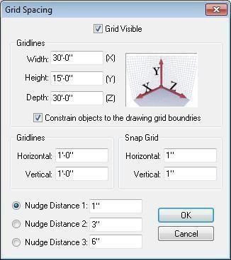
Grid settings are controlled in the Grid Spacing dialog box.
- Grid Visible checkbox turns the grid on and off. When selection the grid is visible. To hide the grid, deselect the checkbox.
(alternatively) Click Design menu > Grid Visible (when a checkmark is visible the grid is enabled).
- Width, Height, and Depth Gridlines text boxes control the size of the grid along that corresponding axis. Type the size you want for each grid pane in these text boxes.
- Constrain objects to the drawing grid boundaries checkbox keeps objects within view on the grid when enabled. When disabled, objects can be moved beyond the grid.
- Gridlines text boxes control the Horizontal and Vertical distance between the individual grid lines.
- Snap Grid text boxes control the Horizontal and Vertical distance your cursor snaps to along the respective gridline.
- Nudge Distance is the distance a selection moves when using nudge. For more information, see “Setting a Nudge Distance”.
To change grid settings 
- On the Grid Toolbar, click the Grid Properties button. The Grid Spacing dialog box is displayed.
(alternatively) Click Design menu > Grid Properties.
- Configure the Grid Spacing properties as needed and then click OK.
To control snap to grid 
- On the Grid Toolbar, click the Toggle Snap to Grid button. When the minor grid lines are visible, Snap To Grid is enabled.
(alternatively) Click Design menu > Snap to Grid. When a checkmark is visible, Snap to Grid is enabled.
Note: To adjust the snap to grid settings, see “Changing Grid Settings”.
Setting a Nudge Distance
With Nudge, you can move objects in a specific direction and in definable increments. The up, down, left, and right selections are also available by using the arrow keys on your keyboard. Through the Grid Spacing dialog box, distances as small as one inch may be defined. You can set up to three pre-defined nudge distances to choose from.
To change the nudge distance 
- On the Grid Toolbar, click the Grid Spacing Tool. The Grid Spacing dialog box is displayed. (alternatively) Click Design menu > Grid Spacing.
- Select the radio button corresponding to the nudge distance you want to edit.
- Type a custom distance in text box and then click OK.
To move an object by nudging
-
Choose the drawing grid you want to move along and then click to select the object you want to nudge.
-
Use the arrow keys on your keyboard to nudge the selection in that direction along the active grid. (alternatively) Click Edit menu > Nudge, then click the direction (up, down, left, or right),
Elevation Slider
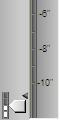
With the Elevation Slider, objects can easily be moved vertically, regardless of which grid is active at the time. The Elevation Slider will display in the unit of measure specified in the home design program; for example, measurements will be displayed in metric automatically, if you are designing in your home design program, using metric measurements.
To use the elevation slider
- Click the Show/Hide Elevation Slider Tool. The Elevation Slider is displayed.
(optional) Right-click the Elevation Slider and choose the measurement increments. The increments depend on the unit of measure you’ve specified in the main application.
- Click to select the object you want to elevate.
(optional) To elevate multiple objects to the same elevation, hold down SHIFT
and click each object you want to elevate.
- Drag the elevation control up or down until the object is at the correct elevation.
To specify an exact elevation
- Click to select the object you want to elevate.
(optional) To elevate multiple objects to the same elevation, hold down SHIFT and click each object you want to elevate.
- Right-click the Elevation Slider and click Set Elevation on the context menu that is displayed.
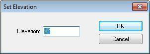
- Type the elevation in inches, or feet and inches, separated with a hyphen and then click OK.
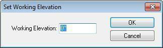
To set the working elevation
- While nothing is selected on the workspace, right-click the Elevation Slider and click Set Working Elevation from the context menu that is displayed.
-
Type the necessary elevation in inches, or feet and inches, separated with a hyphen. Click OK.
-
To enable the working elevation for drawing, right-click the Elevation Slider and click Enable Working Elevation.
Tracing an Imported Image
If you have an image you want to re-create and use in your drawing, for instance a scanned piece of furniture or door design you like, 3D Custom Workshop lets you trace objects directly over that image. You can import you image to one of the available grids using the Image Trace Properties dialog box. Once imported, use the drawing tools to trace the image.
Note: To view an image on Floor Grid, you must be in 2D Profile View and Wire Frame rendering style.
Note: To view an image on the Front Grid, you must be in 2D Front View and Wire Frame rendering style.
Note: To view an image on the Side Grid, you must be in 2D Left View and Wire Frame rendering style.
To import a trace image
-
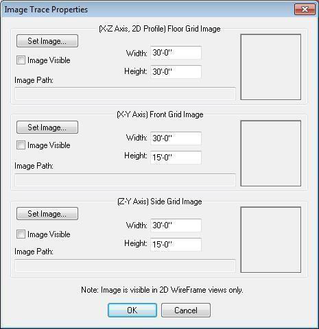
Click Design menu > Image Trace Properties. The Image Trace Properties dialog box is displayed. You can import an image to one of the three grids.
-
Click the Set Image button that is associated with the grid where you want the image to be placed.
-
In the Open dialog box, select the file you want to trace and then click Open. The image is displayed in the Preview Box.
(optional) Select the Image Visible checkbox to turn on the image’s visibility. (optional) Type a Width and a Height value in the corresponding text boxes.
- Click OK.