Door Designer
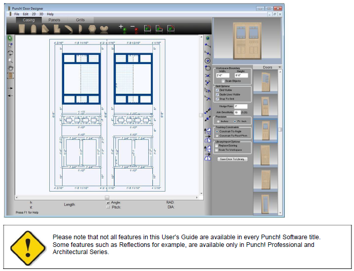
Whether you’re drawing custom grillwork or simply designing a door for a unique space, Punch! Door Designer lets you create custom doors that render like any other door in Punch! Home Design Software. Once placed in your design, you can edit doors created with Door Designer just like the other doors in your custom library.
Designing Custom Doors
With Door Designer you can create custom doors by using unlimited combinations of the three door components.
Door Casing is the trim that surrounds the door opening. You can draw a simple rectangular opening or you can combine shapes to create a more ornate door casing.
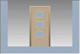
Door Panels are added to your design by drawing 2D shapes within the confines of the casing. By varying the thickness of the panels, you can create raised panels to define the door.
Grills add elegance to your door design after you have added the casing and panels. As you draw, you can set the width of the grills on the Properties Bar. If you want your door design to include glass, simply leave those areas empty.
Launching Door Designer
-
Click Design menu > Launch PowerTool. The PowerTool Launcher is displayed.
-
Click to select Door Designer and click the Launch button. The Door Designer is launched.
Drawing Door Components
You can modify an existing custom door design or draw your own custom doors from scratch. As you draw each component, Punch! displays your door design in 3D. Door Designer has three component drawing modes that let you design doors from the outside to the inside.
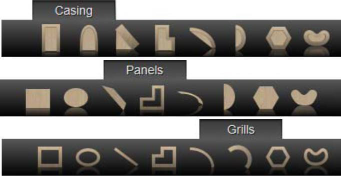
- Casing Start by drawing the trim to surround your custom door. The Casing tab includes tools for drawing the trim casing.
- Panels Next, draw the wood panels that comprise the visible body of your door. The tools on the Panels tab are designed to provide flexibility as you draw.
- Grills Finally, add detailed grillwork to aesthetically define windows in a door. If you want your door design to include only glass, simply leave those areas empty.
Each of the three component drawing modes features an
assortment of 2D drawing tools. The geometry of all three modes is drawn the same. For best results, use these tools in conjunction with Snaps and editing tools to reshape door elements—minimizing repetition and increasing accuracy. For more information about using editing tools, see “Editing Your Door Design”.
For more information on using drawing tools, see “Detail Plan Tab”.
Tip: When drawing multiple instances of a door component, be sure to turn Auto Reset off. On the 2D menu, click to uncheck Auto Reset Tools. When Auto Reset Tools is unchecked, you can draw concurrent door components without selecting the corresponding door tool each time.
Door Component Properties
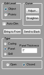
The casing, panel, and grill door component properties are displayed when the component is selected in the design window. You can affect the properties of more than one component by holding the SHIFT key as you click to select multiple components.
- Edit Level Select Object to resize the whole object or Points to edit individual points on the shape. For more information, see “Editing Detail Shapes”.
- Auto-Dimension checkbox controls the displays of dimensions in 2D. When selected, dimensions are displayed.
- Bring to Front button moves the selection to the top layer while Send to Back button moves the selection to the bottom layer.
(alternatively) Click Edit menu > Bring To Front or Send to Back.
- Type settings specify the component type.
- Thickness defines the thickness of the polylines in the shape (applies to panel and grill components only).
Open & Closed options specify if the shape is open-ended or contained.
Editing Your Door Design
Rather than draw each geometric feature of your door casing, panel, or grill separately, use Door Designer’s editing tools to reshape, reposition, re-orient, or even join existing door elements. You can manipulate shapes to match your custom design by inserting or removing points and rounding or chamfering corners. Join tools allow you to join lines, arcs, and polylines into a single entity for editing purposes.
For more information on flipping and mirroring objects, see “Flipping & Mirroring Elements”. The following options are available for editing your door design:
 Selection Tool (
 For more information, see “Moving a Selection” and “Reshaping and Resizing 2D Objects”).
 Rotate Tool (For more information, see “Rotating a Selection”)
 Resize Segment Tool (For more information, see “Changing Segment Length”)
 Add Point Tool (For more information, see “Editing Detail Shapes”)
 Remove Point Tool (For more information, see “Editing Detail Shapes”)
 Fillet Tool (For more information, see “Editing Detail Shapes”)
 Inverted Fillet Tool (For more information, see “Editing Detail Shapes”)
 Chamfer Tool (For more information, see “Editing Detail Shapes”)
To select the next-door element 
- On the Standard Toolbar, click the Select Next Object Tool. Door Designer selects the objects in the order you placed them.
To select the previous door element 
- On the Standard Toolbar, click the Select Previous Object Tool. Door Designer
selects the objects in reverse order.
To join arcs, lines or polylines 
- Click the Selection Tool, then hold down SHIFT and click to select each element that you want to be joined.
Note: The end points of each element must be nearby for those elements to be joined. You can increase or decrease the necessary distance by changing the Join Sensitivity, see “Controlling Drawing Settings”.
2 On the Standard toolbar, click the Join Tool. The objects are joined into a polyline. 
Note: You can separate the segments of any polyline (whether or not you created it using the Join Tool) by selecting the polyline and clicking the Unjoin Tool on the Standard toolbar. 
Flipping & Mirroring Elements
The Flip function takes the original component and reverses it either horizontally or vertically. Mirror works similarly to the Flip function. The difference is that mirror leaves the original and makes a duplicate. Mirror creates two identical components facing one another.
For more information, see “Flip and Mirror”.
Controlling Drawing Settings
There are a variety of tools that allow you to control how you draw, select, or modify door elements. The Properties Bar lets you modify a variety of settings, including the number of sides on a multigon or the size of your workspace. Note: Be sure to press ENTER to accept new values in text boxes.
- Workspace Boundary defines the size of the drawing space. Type new values in the Width and Height text boxes.
If you have already drawn objects in the design window, select Scale Objects to resize them accordingly.
- Grid Options control the grid settings. For more information, see “Using the Grid”.
- Nudge Rate defines the distance a selection moves when nudged using the arrow keys. Type a new value in the text box to change it.
- Join Sensitivity defines how close elements must be in proximity to another element when joining them. A lower value means that you must position elements closer to join them.
- Drawing Precision specifies Inches or Feet-Inches as the unit of measurement.
- Tracking Constraints setting control if the angle of a segment being drawn is constrained to a 5-degree increments or to the roof pitch value. When Constrain to Roof Pitch is selected, polygons and lines at the top of the door design automatically constrain to the roof pitch in your home design
- Replace Existing checkbox controls if door styles that are added from the Preview bar replace the existing components in the design window. When selected, components are replaced when door styles are applied; when deselected multiple styles are applied to the design window.
- Scale to Workspace checkbox controls if door styles that are added from the Preview bar match the workspace size. When selected, styles are automatically scaled to match the workspace size; when deselected the default door style is retained.
- Save Door to Library For more information, see “Managing Door Designs”.
Using Snaps to Draw Components
Punch! Home Design Software includes the power of snaps. With snaps, you can define exactly what distance door elements are placed from other door elements. You can TAB through the Snaps Toolbar. Each time you press TAB, the next Snap Tool is activated, SHIFT+TAB reverses the process.
Note: Each Snap Tool defaults back to “No Snap” after it is used; double-clicking the Snap Tool will lock it in active mode.
Below is a description of the snap tools, from the top of the toolbar to the bottom.
 No Snap Deactivates an active snap tool.
 Snap to End Point The shape snaps to the nearest end point.
 Snap to Segment Center The shape snaps to the nearest segment center point.
 Snap to Object Center The shape snaps to the center point of the component.
 Snap to Object Corner point the shape snaps to the corner point of the component.
 Snap to Intersection The shape snaps to the nearest intersection point.
Snap to Perpendicular
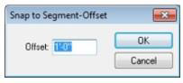
 Snap to Segment-Offset The shape snaps to a point based on an offset distance you specify before drawing the shape.
 Snap to On-Segment The shape snaps to the nearest component segment.
Viewing your Drawing in 3D
Door Designer displays your door design in 3D in the upper right corner of the Door Designer screen. You control the 3D view in the same way you control a 3D View rendering using Fly-Around mode.
To view your door in 3D
- Drag in the 3D view to navigate in fly-around mode. The view is updated dynamically.
To increase or decrease the Fly-Around speed
- Click 3D menu > Helicopter Speed and then select a speed setting from the submenu. The faster the viewing speed, the lower the quality of the rendered 3D image.
To reset the 3D view
- Click 3D menu > Reset 3D View.
To view a window design using ClearView
- Click 3D menu > Render ClearView.
To render a window design in 3D final quality
- Click 3D menu > Render 3D Final Quality.
To automatically render a window design in 3D final quality
- Click 3D menu > Auto Final Render.
To set 3D render quality
-
Click 3D menu > 3D Final Quality and choose the render quality you want from the submenu.
-
Low results in a fast rendering speed, but lower quality output.
- High results in a moderate rendering speed and average quality output.
- Ultra High results in a slower rendering speed and a high-quality output.
- Excellent results in a very slow rendering speed, but a very high quality, sharp output.
Managing Door Designs
Door Designer not only allows you to save new doors for use in your Punch! drawings, it also has easy-to-use tools for organizing and managing door libraries.
To import an existing door design
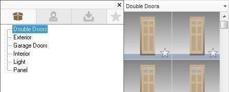
- On the Properties Bar, click the Doors drop-down, then select a Door library. The Preview Bar changes to display doors in this library.
(optional) On the Properties Bar, select the Replace Existing checkbox, to remove existing door designs from the design window as you import from the library. When this checkbox is unchecked, imported designs are placed on top of existing designs.
(optional) On the Properties Bar, select the Scale to Workspace checkbox to automatically resize the door design to the current workspace size as you import from the library.
- Click a door design on the Preview Bar and drag it into the design window.
To save a new door design
- Click the Save Door to Library button on the Properties Bar. The Save Door to Category dialog box is displayed.
(alternatively) Click File menu > Save Door to Library.
- In the Door Category section, click to choose the door category.
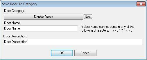
(optional) Click New to create a new door category. Select a folder in which to create the new category, then type a name for the new category and click OK.
-
Type a name for the new door in the Door Name text box. New door names can contain up to 44 characters.
-
Type a description of the new door in the Door Description text box. New door descriptions can contain up to 78 characters.
-
Click OK.
Placing Custom Doors in Your Punch! Drawing
Once you’ve designed a custom door, you can place it in your Punch! design as you would any other door, making sure to select the custom door library before you place the door. In the 2D design window, custom doors are displayed the same as standard doors, but they are fully rendered in 3D View.
To add a custom door 
-
On the Floor plan toolbar, click the Door Tool. The Door Properties are displayed on the Properties tab.
-
Click the Door Style button, then click the Custom Door style at the bottom of the list. The Door Preview Bar is displayed

-
Click the arrow next to “Doors” at the top of the Preview Bar to display the door library list, then click a library. Its contents are displayed in the Preview Bar.
-
Click a door in the Preview Bar to select it.
-
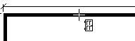
On the Design window, click a wall where you want to place a door.
- (optional) Click to set the door swing, if necessary.
- (optional) Type the Width, Height, Elevation, and Trim Width to customize them.
Note: Any changes made on the Door Properties Bar, become the default and will be used the next time a door is placed.