Control Your Design
Punch! Home Design Software makes it easy to control your working environment. From setting the plan scale and units of measure to defining your ceiling heights on any floor of your design, all these tools are available on the Design Menu.
Punch! Home Design Software even lets you import a scanned image into the background of your design. Once scanned and loaded into your design file, you can trace it to create a Punch! Home Design Software floor plan. You can even set the scale of the new drawing to the scale of the image. When you are done tracing, you can save the new file without the background bitmap image.
Find or sketch your favorite floor plan design. Using a scanner, digital camera or with the help of a scanning service, scan the plan and save it in one of the most popular formats.
The designer or owner of most home plans holds the copyright to them. Make sure you have permission before you copy a plan.
Setting the Working Elevation

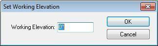
Before you draw, be sure to set your working elevation. All entities are drawn in relation to this elevation. There are two methods for setting the working elevation: The Elevation Bar and the Design menu.
-
While nothing is selected in the design window, type the working elevation you want, in inches, or feet and inches, in the Elevation Bar then press ENTER. Subsequently-drawn entities are added to the design based on the new working elevation.
-
Click Design menu > Set Working Elevation and type the necessary elevation in inches, or feet and inches, in the corresponding field, and then click OK.
Tip: You can also right-click the design window and choose Set Working Elevation, then type the necessary elevation in inches, or feet and inches, in the corresponding field and click OK.
Setting the Scale
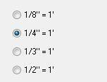
Scale is the ratio between real-world size of objects and items in your drawing and their size when printed. The default drawing scale is 1/4" = 1', meaning that 1/4" on your drawing plan equals one foot in real-world size (or 1:50 for metric meaning 1 cm = 0.5 m). You can customize scale settings at any time to suit your needs, as well as print your drawing to scale.
To set the drawing scale
-
Click Design menu > Plan Scale. The Design Options dialog box opens to the Plan Scale settings.
-
Select a new scale setting, then click OK. The new scale is applied to your plan drawing.
Setting the Units of Measurement
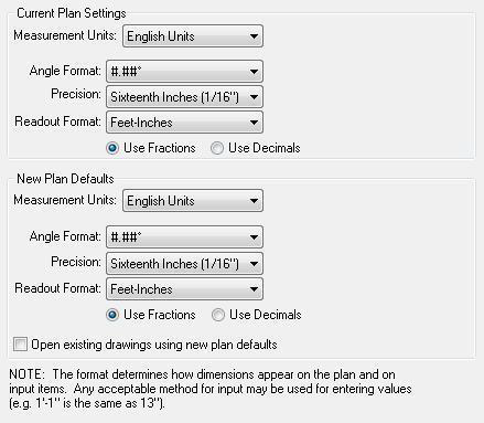
You can set units of measurement by selecting either English or Metric measurements. You can also set the default measurements and options to be applied when any previously-drawn design is opened.
To access unit measurement settings, click Design menu > Unit of Measure. The Design Options dialog box opens to the Unit of Measure settings.
There are two types of measurement settings available. Be sure to edit the settings based on the plan you want them to apply to:
-
Current Plan Settings these settings apply to the plan you’re currently working on.
-
New Plan Defaults these settings are the defaults that apply when you open a new plan (there is an option to open existing plans using these settings as well).
To use English measurements
-
Click Design menu > Unit of Measure. The Design Options dialog box opens to the Unit of Measure settings.
-
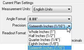
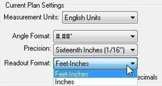
Click the Measurement Units drop-down menu and choose English Units. Edit the Angle Format, Precision, and Readout Format settings as needed and then click OK.
Angle Format defines the number of decimal points you want to use.
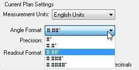
- Precision defines the number of decimal points you want to use.
- Readout Format defines the format you want.
To use Metric measurements
-
Click Design menu > Unit of Measure. The Design Options dialog box opens to the Unit of Measure settings.
-
Click the Measurement Units drop-down menu and choose Metric Units. Edit the Angle Format and Readout Format settings as needed and then click OK.
Angle Format specifies the number of decimal points you want to use.
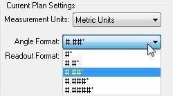
- Readout Format specifies the format you want.

To set defaults for saved drawings
-
Click Design menu > Unit of Measure. The Design Options dialog box opens to the Unit of Measure settings.
-
In the New Plan Defaults section, edit the settings you want existing drawings to use.
-
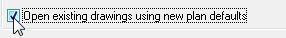
Select the Open existing drawings using new plan defaults checkbox and then click OK. The New Plan Default settings are applied to any previously-drawn design when it is opened.
Defining Lot Properties
The Lot Properties dialog box allows you to control not only the size of your lot, but how it is rendered in 3D. To access lot properties, click Design menu >
Lot Properties. The Design Options dialog box opens to the Lot Properties settings. After editing the settings, click OK.
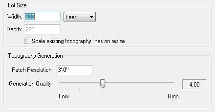
- Lot Size settings define the Width and Depth, in feet or meters. Type values in the corresponding text boxes to define the size of the lot.
Use the drop-down menu to covert the values to either feet or meters. You can also choose the measurement you want before entering the lot size values.
- If you’re editing a design that includes topography lines and you want them to resize based on your lot size, select the Scale existing topography lines on resize checkbox. If you want the topography lines to remain the same size, deselect the checkbox.
- Topography Generation defines the topography generation settings. Type the size of the Patch Resolution you want. A lower value results in a more accurate 3D rendering of your topography but may also impact performance.
Drag the Generation Quality slider to increase or decrease the topography generation quality. Higher generation quality reduces rendering speed.
Update Topography Grid
Punch! Home Design Software keeps track of the changes you make to the topography in your design. If you want to update the topography grid, you can do this with one click.
To update topography grid, click Design Menu > Update Topography Grid. Your topography changes are applied.
Work on Floor
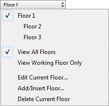
Use the Working Floor button to switch back and forth between the floors in your home plan. To work on a particular floor, click the Working Floor button in the top-left corner of the design window, then choose the floor you want to work on from the drop-down menu that is displayed. The active working floor has a checkmark next to it.
Tip: You can also click Design menu > Work on Floor then click the floor you want to work on.
For information on adding or editing floors, see “Working with Floors”.
Calculate Floor Area
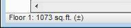
Punch! Home Design Software’s automatically calculates the square footage for each room of your design as you add them. The program also updates the square footage, as you change the walls in your design. You can calculate the square footage for each floor at any time. This feature makes it easy to figure how much carpet you’ll need to cover the first floor, for instance, or simply estimate your overall home size.
To calculate floor square footage, click Design menu > Active Floor Area. The total square footage for the current floor is calculated and displayed in the Status Bar.
Note: The square footage calculation is based on walls' interior area (surface to surface).
Floor Plan image Trace
After you have scanned the plan you want to trace and saved it, you are ready to import into Punch! Home Design Software. You can import a floor plan image onto the main floor, and then onto the second or third floor also. To be sure all floors line up correctly, scan all plans at the same size and match the scale identically.
Note: You can import a plan to trace in any of the following file formats; BMP, JPG, PNG, TIF, or PTX.
Import a Floor Plan Image
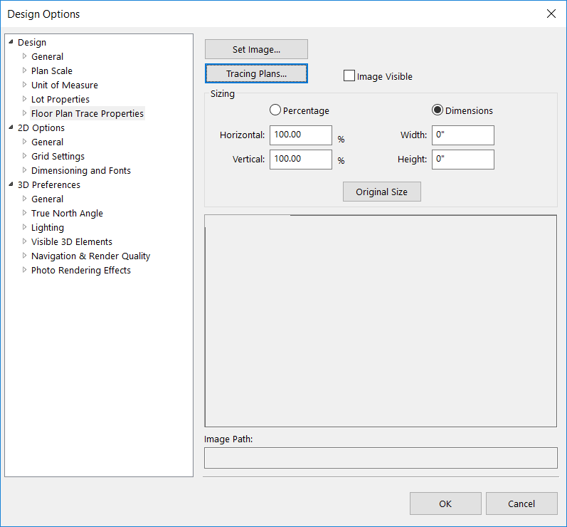
Floor plan images are imported through the Floor Plan Trace Properties option in the Design Options window. If you know the size of image you want, you can specify the percentage or dimension values. Otherwise you may need to adjust the image based on scale after you’ve imported.
Once you’ve imported the plan image, you can trace the image using the wall tools, add electrical and plumbing components, landscaping, and much more.
To import a floor plan image
-
Click Design menu > Floor Plan Trace Properties. The Design Options dialog box opens to the Floor Plan Trace Properties.
-
Click the Set Image button and locate the file you want to import.
-
Select the file and click Open. A preview of the floor plan loads in the Design Options window. (optional) Edit the Sizing settings using either Percentage or Dimensions.
-
Click OK to load the image in the design window.
Match the Drawing Scale
If the imported floor plan is not the correct size, you can scale it in Punch! Home Design Software. This process involves creating a measurement in Punch! based on a known segment, wall length, or distance in your plan drawing, and then resizing the plan to match the measurement. To do this, you need to know at least one segment length or distance you can base your measurement on. Be sure to use the same scale when preparing to trace an upper floor.
Note: If you need the imported image to be larger, the percent you enter will be greater than 100%. Conversely, if you need the image to be smaller, the percent will be less than 100%.
To match the drawing scale
-
Import a plan image. For more information, see “Import a Floor Plan Image”
-
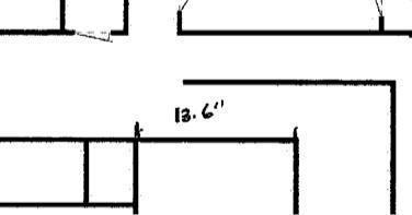
Identify a wall section or segment in the plan that has a known length. This is the reference point for your measurement.
-
Use the Virtual Ruler or one of the Dimension Tools to measure the distance of the wall section or segment in the plan.
-
Position the Virtual Ruler or Dimension Tool parallel to the segment and extend it to match the known length on the image.

Note: It is best to measure along a longer wall to minimize the margin of error when scaling.
- Click Design menu > Floor Plan Trace Properties and click either the Percentage or Dimensions, depending on which method you want to use to resize the image.
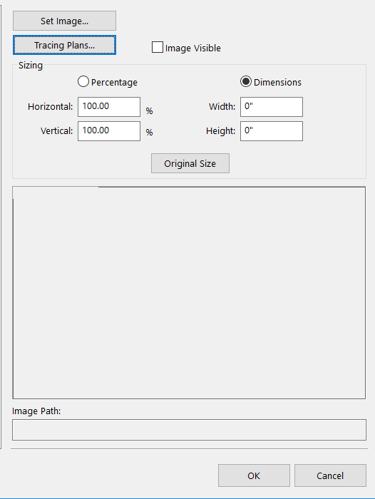
- Type values in the Horizontal and Vertical text boxes to equal amounts, to change the scale of the entire drawing in proportion and click OK.
Continue to adjust the percentage or dimension values until you have matched the scale.
Show/Hide an Imported Floor Plan
There may be times when it is easier to work on your floor plan if the tracing image is not visible. It is easy to toggle the Floor Plan Trace image on and off.
To control the floor plan trace image visibility
- Click Design menu > Show Floor Plan Trace Image. The image is visible when there is a checkmark next to this menu listing.
OR
- Click Design menu > Floor Plan Trace Properties and select or deselect the Image Visible checkbox, then click OK.
Design Options
The Design Options window provides access to the majority of settings you’ll need outside of the actual drawing tools.
You can control options like unit of measure, dimension and text fonts, lighting, and many more design options.
To access the design options
- Click Design menu > Design Options.