Controlling Views
You can control the way you see your design in 3D Custom Workshop. These views can make editing much easier or can simply make it clearer to view specific areas of your drawing.
In this chapter you will learn to use ClearView, perspective, orthographic, textured, and Wireframe views. You will also learn how to zoom in on a specific area and how to set the camera angle.
Using Zoom and Pan
At some point while illustrating your object, you may want a close-up view of a specific area. By using the zoom and pan tools in concert with the set zoom feature, you will be able to view any area of your drawing with pinpoint accuracy. With the Pan Tool, you can move the window to view a different area of the drawing without changing the magnification.
To zoom in or out of your drawing 
-
On the Standard Toolbar, click the Zoom Tool.
-
Click on the design window and drag up to zoom in; drag down to zoom out. (alternatively) Zoom in and out easily with the wheel on your mouse.
Note: The location of the cursor will be centered on the design window.
To set a specific zoom percentage
- Double-click the Zoom Tool. The Set Zoom dialog box is displayed. (alternatively) Click View menu > Set Zoom.
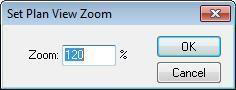
- Type a zoom percentage into the Zoom text box and click OK.
To pan across the drawing
-
On the Standard Toolbar, click the Pan Tool.
-
Hold down the left mouse button and drag in the direction you want to view. The view changes, dynamically, as you move the mouse.
Using Perspective or Orthographic 3D Views
Perspective view is the default view in 3D Custom Workshop. Perspective views give more information about depth and are often easier to view because they are similar to a “real world” view. In Perspective View, the parts of the drawing that are nearest to you will appear larger than those further away.
Orthographic viewpoints make it much easier to compare, for example, two parts of the object, as there is no question of how the viewpoint may affect the perception of distance.
Perspective View Orthographic View
To set a 3D view 
- Click the Viewing Options button and choose Perspective or Orthographic from the
pop-up menu. (alternatively) Click View menu > View in Perspective or View in Orthographic.
Using Different Views
Using the rendering styles, you can literally see your design inside and out. 3D Custom Workshop’s technology includes anti-aliased, photo-realism. You can even create glass-topped tables by setting the Translucency of an object.
By default, objects are displayed in Shaded View. To speed up rendering times, you can set the default view so objects are displayed, first, in Wireframe.
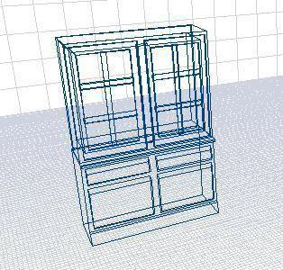
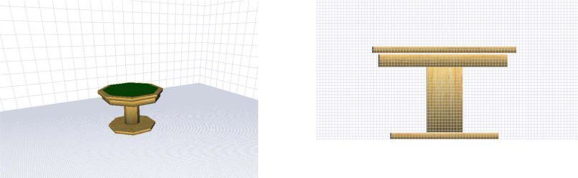
Wire Frame
In Wireframe view each individual line or arc is visible and able to be changed; detailed editing of the object may be easier in Wireframe view. While viewing in Wireframe, you can control the appearance of the point handles, making them large, small, or turning them off completely.
To view Wireframe mode 
- Click the Rendering Style button so the Wire Frame style is displayed. (alternatively) Click View menu > 3D Rendering Style > Wireframe.
To set Wireframe as your default view 
-
Click the Custom Options button. The Custom Options dialog box is displayed. (alternatively) Click Options menu > Custom Options
- Select the Start in Wireframe Mode checkbox and then click OK.
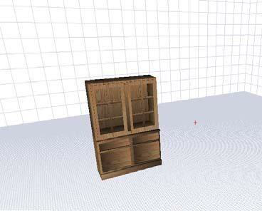
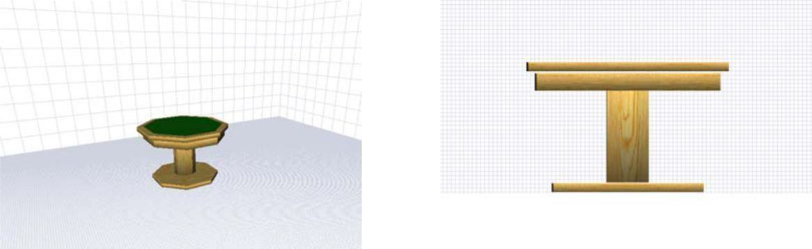
Shaded View
Textured, shaded view gives a more realistic appearance and is the default view in 3D Custom Workshop.
To view shaded mode 
1. Click the Rendering Style button so the Shaded View style is displayed. (alternatively) Click View menu > 3D Rendering Style >
Shaded View.
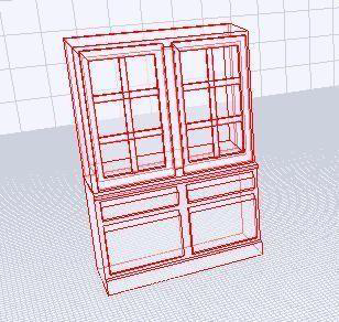
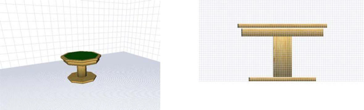
ClearView
While in ClearView, you can view your design in an opaque state.
To view using ClearView
1. Click View menu > 3D Rendering Style > ClearView.
Rendering a 3D View
To view 3D objects in final quality, render the design. You change the default rendering quality, which affects rendering speeds.
To render using 3D final quality
1. Click View menu > Render 3D Final Quality.
To set 3D render quality
1. Click View menu > 3D Final Quality choose one of the options.
- Low results in a fast rendering speed, but lower quality output.
- High results in a moderate rendering speed and average quality output.
- Ultra-High results in a slower rendering speed and a high-quality output.
- Excellent results in a very slow rendering speed, but a very high quality, sharp output.
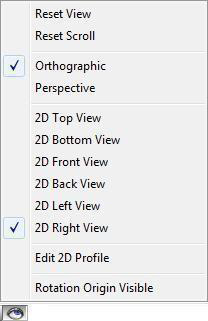
Using 2D Views
2D Views work in harmony with the 3D Views. The 2D Top and Bottom Views are used in tandem with the 3D Floor Grid; the Front and Back Views are used with the 3D Front Grid; the Left and Right Views work with the Side Grid.
The 2D Views make complex alignment straightforward and simple. There are a number of ways to quickly access a 2D view, and it is easy to toggle back and forth between views. All 2D views work in the same manner.
1. Views Toolbar

2. Viewing Options pop-up menu
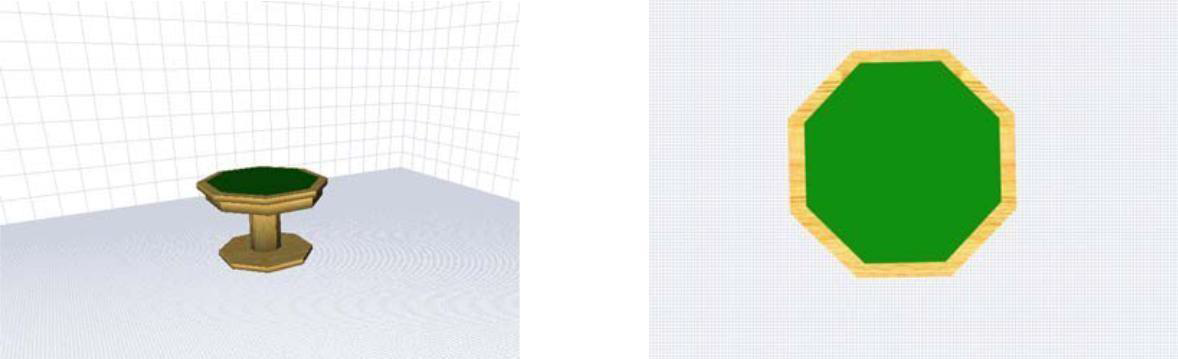
2D Top View
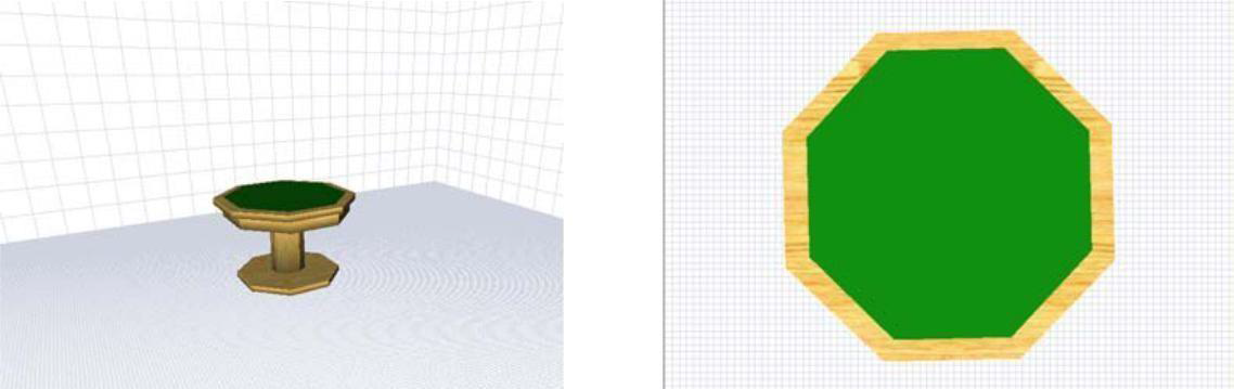
3D Perspective View 2D Top View
2D Bottom View
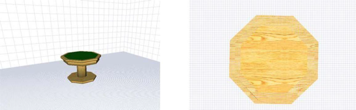
3D Perspective View 2D Bottom View
2D Front View
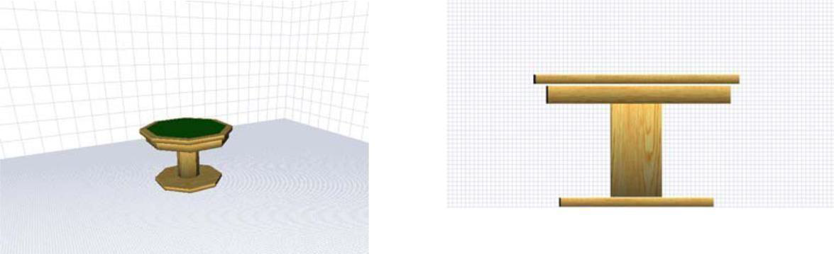
3D Perspective View 2D Front View
2D Back View
3D Perspective View 2D Back View
2D Left View
3D Perspective View 2D Left View
2D Right View
3D Perspective View 2D Right View
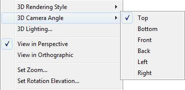
Setting the 3D Camera Angle
With the 3D Camera Angle options, you can view your design from six preset vantage points. They are particularly useful when you need to quickly view a specific area of your design or when you want to line up multiple objects.
To change the 3D camera angle
1. Click View menu > 3D Camera Angle and choose a view from the submenu.
To return to the default view
1. Click View menu > Reset View.
To adjust the lighting intensity
1. Click View Menu > 3D Lighting. The 3D Lighting dialog box is displayed.
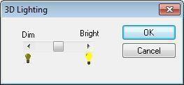
1. Drag the slider to increase or decrease the overall lighting and then click OK.
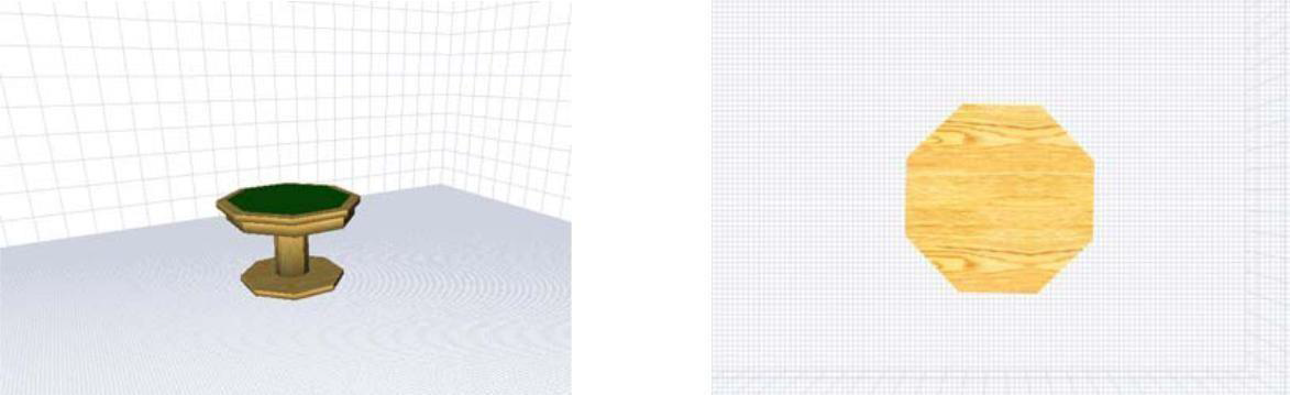
3D Top View
3D Perspective View 3D Top View
3D Bottom View
3D Perspective View 3D Bottom View
3D Front View
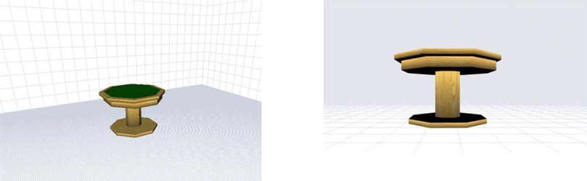
3D Perspective View 3D Front View
3D Back View
3D Perspective View 3D Back View
3D Left View
3D Perspective View 3D Left View
3D Right View
3D Perspective View 3D Right View
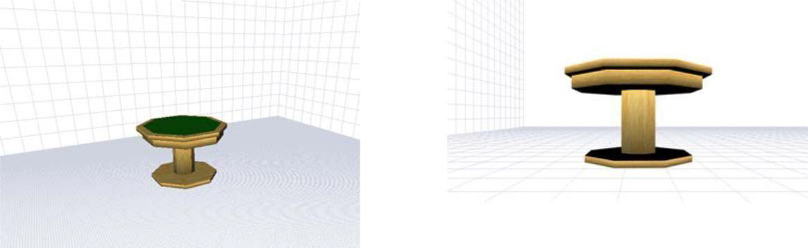
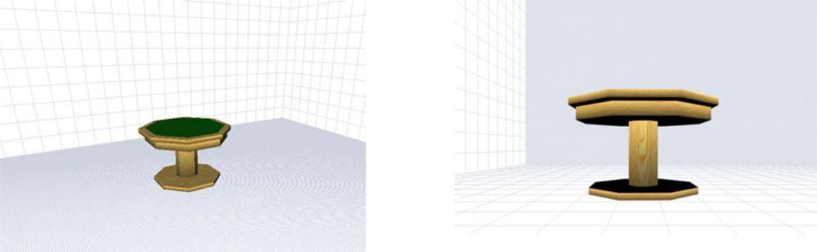
Using Fly-Around
In addition to the preset 3D viewing angles, you can view your design from any other angle using the Fly-Around Tool. The Fly-Around Tool lets you rotate around a point of origin that can be defined with a couple clicks. You can easily rotate around the center of any object, again with just a click or two!
To use the Fly-Around Tool 
  1. On the Viewpoint Toolbar click the Fly-Around button.

  2. Hold down the left mouse button and drag in the direction you want to view. The view changes, dynamically, as you move the mouse.
Note: To fly around one object, right-click the object and choose Center On Object from the context menu and then navigate using the Fly-Around Tool.
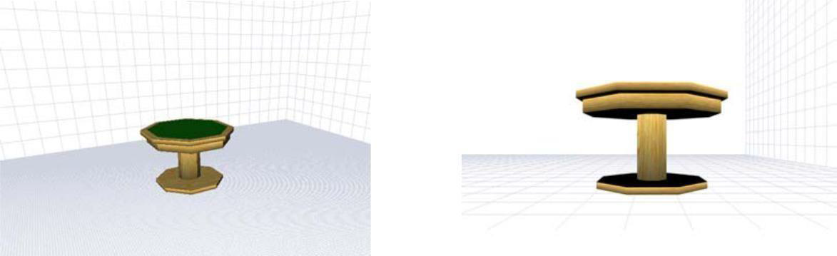
To set the rotation elevation
1. Click View menu > Set Rotation Elevation. The Set Rotation Elevation dialog box is displayed.
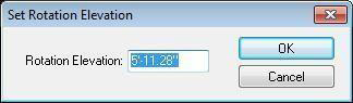
  2. Type the Rotation Elevation you want in the text box and then click OK. To show or hide the point of rotation origin

  3. Click Options menu > Rotation Origin Visible. The Rotation Origin is visible when a checkmark exists.
(alternatively) Right-click the design window and choose Rotation Origin Visible.
Controlling Default Colors
Using the Custom Options dialog box, you can control default colors of specific aspects of 3D Custom Workshop, such as Wireframe, point handles, grid color, new objects, and more.
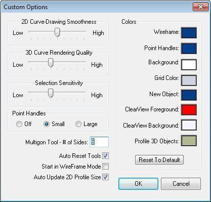
To change a default color 
  1. Click the Custom Options button. The Custom Options dialog box is displayed. (alternatively) Click Options menu > Custom Options.

  2. Click the preview for the color you want to change. The Colors dialog box is displayed.
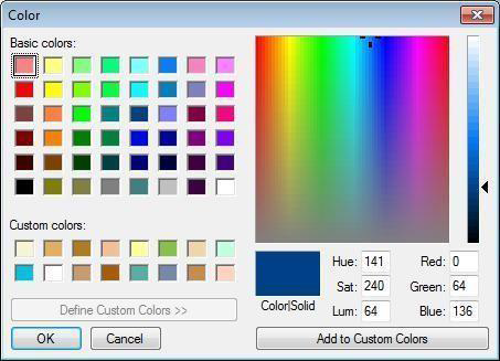
  3. Choose a color from Basic colors, Custom colors, or the color matrix and then click OK. The color you chose is displayed as the new preview color.

  4. Click OK to close the Custom Options dialog box.
To reset default colors 
  1. Click the Custom Options button. The Custom Options dialog box is displayed. (alternatively) Click Options menu > Custom Options.

  2. Click the Reset To Default button and then click OK.
Changing Curve Tension
To further control the look of the shapes drawn with any of the arc or curve tools, you have control over the degree of curve assigned to them. Curve Tension is measured between 1 and 50. Specifying 1 in the dialog box results in very little tension being applied, while specifying 50 is the maximum amount allowed and causes a greatly- exaggerated curve.
For more information, see “Changing Curve Tension”.
Using Nudge and the Grid
Once you’ve placed an object, you can precisely move it into position using Nudge. Nudge utilizes the arrow keys to move selected objects, or features, a specified distance. For more information on using Nudge, see “Nudging a Selection”.
Nudge works in tandem with the Snap Grid. To learn more about the Snap Grid, see “Using the Grid”.
Grid settings have a direct impact on the ease of aligning objects and snapping objects to the grid. When using the Snap to Grid feature, items that are dragged and dropped on the design window are automatically snapped, or placed, to align with the current grid. By default, Snap to Grid is turned on. For more information, see “Using the Grid”.