Solid Utilities
Available in TurboCAD Pro and partially available in TurboCAD Deluxe)
Boolean operations provide the designer with tools for adding, removing, and intersecting solids with other solids. The figure below illustrates the three Boolean operations on two solids.
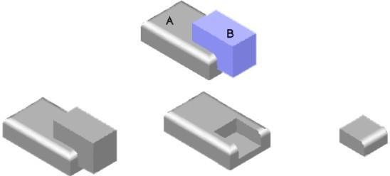
A+B A-B A Intersect B
Boolean Operations
Add(Aavailable in TurboCAD 2D/3D)
The Union Boolean (also called add) operation is used to combine two shapes into one. You can add more than one solid to the base solid (first solid selected).
Using the Union tool
- Select the part to add other parts to.
- Select one or more parts to add to the previously selected part.
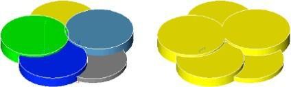
Boolean Union
In the above example, the first solid selected was yellow. The other solids were selected in step 2. The color and material attributes from the first solid are preserved on the resulting part.
Subtract
The Subtract (also called difference) operation is used to subtract material from a solid. Using the Subtract tool
- Select the part to subtract other parts from.
- Select one or more parts to subtract from the previously selected part.
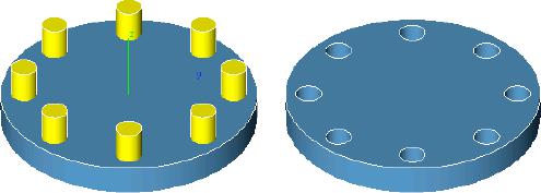
Boolean Subtract
Intersect
The Intersection operation creates a shape equal to their common volume.
Using the Intersect tool
- Create a lens using two spheres and the Intersect tool.
- Select the first part for the Intersect tool. (New part has the color/materials of the first part.)
- Select the second part for the Intersect tool.
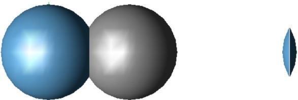
Boolean Intersect
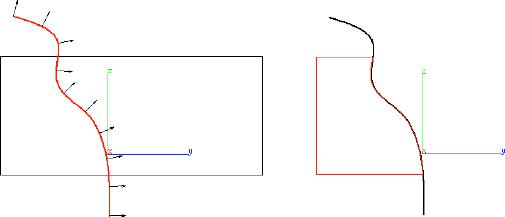
Trim
The Trim Solid tool is used to remove unwanted portions of a solid using a curve or surface. When you pick a curve to remove away portions of a solid, the curve is extended through the screen. Arrows are drawn that indicate the side of material that is to be removed. Use the Option key to flip the direction. You may also pick a surface to trim a solid.
Using the Trim tool
- Pick a curve or surface to trim solid with.
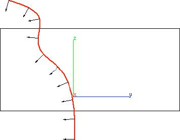
Pick the solid that you want to trim. The trim operation removes the material in the direction of the arrows.
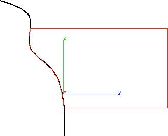
Hit the Option key to toggle the trim to the opposite side.
Split
The Split Solid command divides a solid into two components. You split a solid by first creating an infinite plane surface from the Surface command. Select the plane and the solid to split into two components. The Split Solid command is useful for displaying solid sections in drawings and for creating large stereolithography models.
Using the Split tool
- Pick the solid to split.
- Pick the surface or solid to split the first part.
Split Solid with a Surface (and moved)
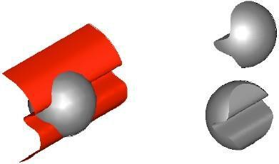
Stitch
The Stitch tool provides a way to stitch, or sew, separate surfaces together to make a solid body that is topologically complete. Internally, stitching essentially involves replacing coincident groups of edges or vertices in the data with a single edge or vertex.
Using the Stitch tool with Surfaces
- Pick one or more surfaces to stitch into a solid.
- Press the Option key for advanced stitching options.
The Stitch tool also allows the selection of a solid. In this case the repair features of the Stitch tool will examine the part and repair any potential problems. In this case, the repair operation is added as a feature operation and repeats the repair operation on regeneration.
Stitch Options
The Stitch command displays a dialog box with advanced settings associated with stitch and healing surfaces.
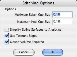
Maximum Stitch Gap Size
The maximum distance between two shared edges.
Maximum Heal Gap Size
The maximum distance the software will attempt to heal two edges. Healing geometry typically involves changing the geometry slightly at the shared vertex or edge.
Simplify Spline Surfaces to Analytics
Examines the surfaces for possible conversion from NURBS to analytic.
Use Tolerant Edges
Instead of healing the two surfaces, just assign a tolerant edge.
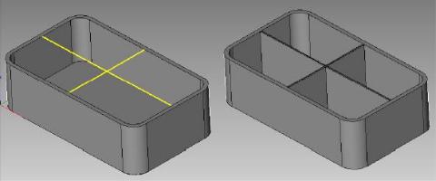
Closed Volume Required
By unchecking the “Closed Volume Required” option, the stitches will not require that the body be watertight. This command allows you to treat collections of surfaces as if they were closed. This then provides a means to do what were previously solid modeling operations on surfaces (sometimes called hybrid modeling). For example, variable radius blends, chamfers, holes, and cutouts can be applied to surfaces as in the illustration below.
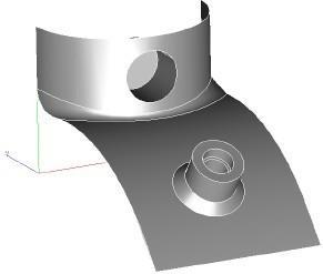
Feature Operations on Surfaces
Thicken
The Thicken tool will thicken a surface into a solid. You can also use the Thicken tool to thicken a specific face or the entire solid. Negative values are acceptable for thickness values. In the case of a surface, a negative value thickens in the opposite surface direction of the surface normals. For solids a negative value will remove volume.
Using the Thicken tool on Surface
- Select a surface to thicken. (Poly surfaces are acceptable as in below example.)
- Use the Data Entry Fields to adjust the thickness value.
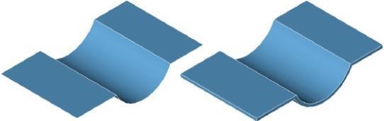
Thicken Surfaces
Using the Thicken tool on Solids
- Select a face or body to thicken.
- Use the Data Entry Fields to adjust the thickness value.
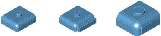
Original SolidSingle FaceEntire
Thicken Face or Body
Lofted Faces
The Lofted Faces tool creates a solid that is tangent between two neighboring solids. The resulting solid automatically joins the two bodies involved into one new body.
Using the Lofted Faces tool
- Select the two faces to loft between.
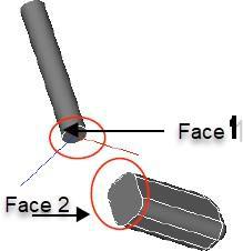
Loft Solid Face Selection
Use the Data Entry fields to change the bulge factor.
Once you’ve created a lofted solid, you can go back and modify the bulge factors using the Inspector. In the image below, object (b) uses two bulge factors, 5 and 5. Object (c) uses 20 for the first and 5 for the second. Object (a) uses 11 and 11 for each face. Be careful not to apply a bulge too high that will result in a self-intersecting body. Also, beware of using too small of bulge factors which will prevent later features operations, such as shelling and blending.
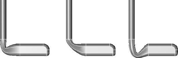
(a) 11,11 (b) 5,5 (c) 20, 5
Bulge Factors for Face1 & Face2
Lofted Faces Guides (Pro Only)
This tool allows you to specify guide curves for the Lofted Solid tool.
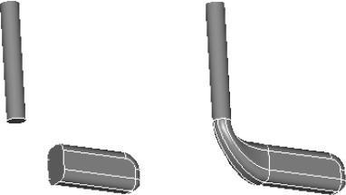
Rib (Pro Only)
The Rib tool is used for the construction of a support feature. It includes parameters for thickness and draft angle, which are set on the Prompt window.
Using the Rib tool
- Select the solid where you want a rib to appear.
- Click the 2D profile that you want the rib to follow.
- Click two points to define the direction of the rib.
Wrap (Imprint, Emboss, Engrave)
Wrap Tool : Engrave Text On Complex Surface
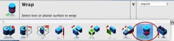
Placing text, company logos, or complex patterns onto 3D surfaces can be a daunting task. Especially if you need to preserve size and scale of the details from the 2D shape to the 3D surface.
The new Wrap tool introduced in V12 maps text or planar surfaces onto a 3D solid model. The results are perfect for imprinting, embossing, or engraving 2D shapes onto 3D surfaces.
Highlights of the wrap implementation:
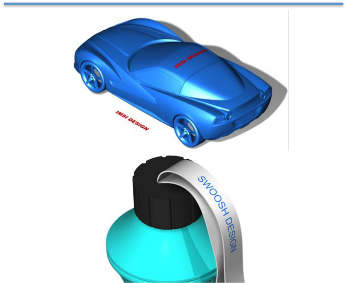
Imprint:
The imprint option takes the 2D wrapping surface and creates new regions on the resulting 3D surface.
These new regions are used to apply color or textures, typically for visualization purposes.
For example, if you are designing a car and need to place a sponsor logo, the imprint may be just the tool you are looking for.
Emboss
The emboss option takes the 2D wrapping surface, imprints regions onto a 3D surface, and then adds offset faces to the part.
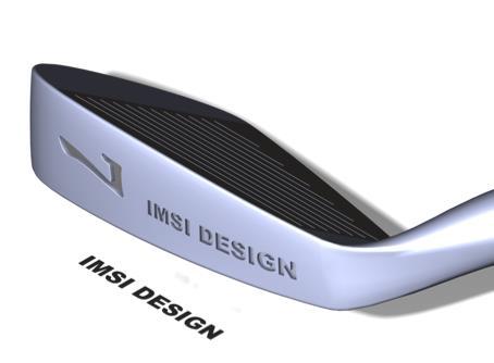
Engrave:
The emboss option takes the 2D wrapping surfaces, imprints regions onto the 3D surfaces, and then subtracts offsets to the part.
For example, if you are designing a ring and want to place an inscription on the inside the ring, you would use the engrave option along with text.