Advanced Material Editing
Available in TurboCAD Pro)
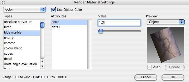
The Advanced Material Editor provides a means to edit existing materials or to create new custom materials. The dialog box provides a pull-down menu to specify one of five Shader Classes. Each shader class supports a variety of shader types. Each shader type has a collection of attribute values that define the characteristic of the shader. This implementation presents over 300 rendering attributes for materials. The preview pane shows the immediate impact of an attribute on the material. Select the auto checkbox for the preview pane to update automatically or use the Update button to do so manually.
Advanced Material Editor
There are two ways to access the Render Material Settings dialog for material editing.
- Right-click (Ctrl-click) an object with a material applied and from the Photo Render submenu, choose Edit Material.
- Select an object with a material applied and, on the Inspector, click the Render tab and choose Advanced.
Advanced Material Button
Shader Class
The Shader Class displays a pull-down menu that contains five classes for defining material Color, Displacement, Reflectance, Transparency, and Texture Space.
Shader Types
The Shader Types list contains all the different shader types for a given shader class.
Attributes
The Attributes list contains all the different attribute types for a given shader type.
Attribute Values
The Attributes value section of the dialog box is the location where you adjust floats, integers, and strings for an associated attribute type.
Preview Sample
The Preview Sample area of the dialog box displays a sample thumbnail image of a shape with the given material settings. Use the object type pull down to change the shape of the geometry used in the preview image.
Color Shader Class
The Color Shader class is used to define the method used to define an object’s base color. The color may be calculated from a variety of methods that include curvature, texture, evaluation, wrapped images, wrapped textures, and decals. The example color shader types are listed below
abs curve
False color shader which shows the ‘absolute curvature’ of asurface.
birch
A version of the general “wood” advanced wood color shader with predefined values appropriate to a birch-likeappearance.
blue marble
A blue marble pattern.
cherry
A version of the general “wood” advanced wood color shader with predefined values appropriate to a cherrywood-likeappearance.
chrome
A color source providing simple chrome-like reflections. The sourcehas a base color, specified by argument “base color”, which is mixed with bands of colors based on the orientation of the surface relative to a direction specified by argument “vector”. A “mix” argument is used to specify the ratio of mixing of base color with the reflection colors. This value should lie in the range 0 to 1, where a value of 1 indicates all base color and no reflection colors.
colour blend
A color shader that blends two wrapped images or user-specified colors together. Blending an image with a colour is also supported. The input textures or colors are mixed using the drop off factor, which changes with the angle between surface normal and the chosen drop off direction.
cubes
A three-dimensional lattice of cubes with alternatingcolors.
| draftangle | Surface evaluation for mold design. The “pull direction” parameter is the |
|---|---|
| direction in which the cast object is supposed to be pulled out of the mold. It | |
| will not be possible to pull it out if part of mold “overhangs” the object, i.e. | |
| angle between pull direction and surface normal is smaller than 90 deg. If | |
| there is a part of surface that has such property then it will be marked with | |
| “overhang color”. Next it will be impossible to pull the object out if tangent | |
| to the surface is parallel or almost parallel to the pull direction. They must | |
| differ by at least “draft angle” (usually 1 deg). So, the parts of surface with | |
| normals that form angles between 90 deg and 90 deg + “draft angle” will be | |
| marked with “fail color”. The parts of surface with normals that fall into | |
| range between (90 deg + “draft angle”) and (90 deg + “draft angle” + | |
| “tolerance angle”) can be pulled out, although with some difficulty. So, they | |
| are marked with “warning color”. Finally, if the surface normal forms any | |
| angle between (90 deg + “draft angle” + “tolerance angle”) and 180 deg with | |
| “pull direction” everything is nice and those areas are marked with “pass | |
| color”. Each of the angles must fall into the range (0, 90) deg and also their | |
| sum must fall into this range. Otherwise the default angle values are used. | |
| The length of the pull direction vector must be greater than 0.0001. | |
| Otherwise the default pull direction is used. Setting 0.0 for “draft angle” | |
| results in “fail color” zone disappearing. | |
| Setting 0.0 for “tolerance angle” results in “warning color” zone | |
| disappearing. | |
| Setting both angles to 0.0 results in having displayed “pass color” for normal | |
| directions opposite to “pull direction” and “overhang color” for normal | |
| directions consistent with “pull direction”. | |
| fleck | Color shader which creates a pattern with coloured flecks as seen in some |
| plastics, composite materials or tiles. | |
| gauss curve | False color shader which shows the “gaussian curvature” of a surface. |
| outcurve | False color shader which shows the selected type ofsurface curvature |
| (absolute, mean or gaussian) by false color encoding. | |
| granite | A solid texture giving a granite like pattern. |
| layered | A shader that combines color from layers defined by color shaders. Any |
| color shader can be used for the base layer, the shaders for the layer above | |
| should be ones that allow the background color to show through, such as | |
| “wrapped paint splat”. | |
| maple | A version of the general “wood” advanced wood color shader with |
| predefined values appropriate to a maple-likeappearance. | |
| marble | A marble pattern. |
| mean curve | False color shader which shows the ‘mean curvature’ of a surface. |
| oak | A version of the general “wood” advanced wood color shader with |
| predefined values appropriate to an oak-likeappearance. | |
| paving | A color shader creating patterns of pavings made of irregular stones. |
| pine | A version of the general “wood” advanced wood color shader with |
| predefined values appropriate to a pine-like appearance. | |
| plain color | A plain, uniform color. |
| simple wood | A simple wood pattern with concentric rings of light and dark wood. |
solid clouds A cloudy appearance.
solid polka A solid polka-dot pattern.
survival Color shader which simulates reflection of a cylinder withlongitudinal bands surrounding the surface being considered. Gives good visual clues to the surface’s curvature.
turbulent the shader simulates turbulent medium variations (smoke, patchy fog).Although designed for use as medium density defining shader for “scattering medium” foreground it may be used also on its own for interesting surface effects.
wood A solid texture corresponding to a wood pattern. The wood is based around the idea of having a tree trunk centered on a given axis with concentric rings of light and dark wood colors. This shader provides more subtle control over the pattern than the more basic “simple wood” shader. Using all the features of this shader it is possible to recreate the appearance of virtually any type of wood. For common types of wood such as oak, maple, birch, cherry and pine, however, specific shaders are provided which simply have the relevant values for the arguments preset (color shaders “oak”, “maple”, and so on). It is recommended that, for most applications, you begin with one of these shaders and modify argument values gradually to achieve the effect you want. The arguments/features of this general shader are presented here so that you can see how to create your own specific types of wood if you desire. The orientation of the tree from which the wood is taken is specified by a point which lies on the axis in argument “trunk center” and a directionvector pointing along the axis of the tree in argument “trunk direction”.
An overall scaling factor is supplied in argument “pattern scale”, which determines the radius difference of two adjacent rings. 0.01 means that there are 100 rings per unit length along the trunk radius. Choose a value appropriate to the units in which your geometry is modeled. The default value is appropriate for modeling in meters. The color of the rings and the wood between the rings is specified in arguments “ring color” (the darker rings) and “wood color” (the lighter colored wood representing spring growth in the tree), respectively. The width of the rings relative to the tree’s trunk is specified by argument “ring width”. 0.0 means no ring at all; 1.0 means that all the trunk area is covered by the ring color. The default value, 0.5, gives a reasonable look for many simple situations. Only values between 0.0 and 1.0 are acceptable. In addition, the “fuzziness” of the boundary between the areas of ring color and standard wood color can be specified using the arguments “ring fuzz in” and “ring fuzz out”. These specify the sharpness of the edges of the inside and outside of the rings respectively (the values actually represent the fraction of the ring width over which the interpolation from one color to the other is done). Values between 0.0 and 1.0 are acceptable. Again, sensible default values have been chosen for these values, which essentially represent common growing cycles in temperate climates (a reasonably quick start of new growth in the spring followed by a slower decline in growth during the late summer). The “gnarl” argument allows random perturbation of the regular rings inside the trunk. This allow localized “knot” patterns to form, for example. The higher value of the parameter the more “gnarled” the rings pattern becomes.
This shader also accounts for the appearance of random flecks or grains within the wood pattern, and for random perturbations of the ring pattern, which helps give a much more life-like appearance to the wood. The “grain” parameter determines the intensity of the random grain effect. 0.0 means no grain at all, with higher values making the grains more distinct and visible (values in the order of 0.5, 1.0 or 2.0 create reasonable effects). The color of these grains is specified by the argument “grain color”. The amplitude of the high-frequency perturbations of the ring edges is controlled by the argument ring fuzz grain. (the value represents the fraction of the ring width over which the largest perturbations extend – values of less than 0.5 are recommended). Finally, “grain scale” determines the size of the grain in relation to ring size (both the random grain flecks and the ring fuzz grain). Values between 0.1 and 2.0 are reasonable – 1.0 means that the grain size is comparable to the distance between two adjacent rings.
wrappedbirchfloor
A version of the general “wrapped wood floor” color shader with predefined values appropriate to a birch-like appearance.
wrapped brick
A wrapped brick pattern.
wrappedbrickbonds
an extended wrapped brick pattern.
wrapped brick
A wrapper brick pattern.
formation wrapped checker
A wrapped checker board pattern.
wrappedcherryflr
A version of the general “wrapped wood floor” color shader with predefined values appropriate to a cherrywood-like appearance.
wrapped diagonal
A pattern giving a line across the leading diagonal of the texture space.
wrappedfilteredimg
A wrapped texture to provide image color mapping with additional color filtering.
wrappedgridcolor
A grid color pattern.
wrappedimagecolor
A wrapped texture to provide image color mapping.
wrappedmaplefloor
A version of the general “wrapped wood floor” color shader with predefined values appropriate to a maple-like appearance.
wrappedoakfloor
A version of the general “wrapped wood floor” color shader with predefined values appropriate to an oak-like appearance.
wrappedpaintslab
Paint splat effect shader that emulates paint dots on a plastic surface.
wrappedpinefloor
A version of the general “wrapped wood floor” color shader with predefined values appropriate to a pine-like appearance.
wrappedpolka
A wrapped polka-dot pattern.
wrapped random image
A shader that returns colour of one of the specified colour shaders (which would normally be images) based on a selector argument. Each of the supplied images can be rotated giving four variants for each image shader to choose from.
wrappedrooftiles
Wrapped color shader simulating various styles of roof tile.
wrappedsstripe
A pattern giving a line along the s-axis of the texture space.
wrappedtstripe
A pattern giving a line along the t-axis of the texture space.
wrappedtexturedbrk
A wrapped texture to textured brick pattern.
wrappedwoodfloor Reproduces wooden flooring using a number of different plank replication patterns and wood types.
Displacement Shader Class
The Displacement Shader Class is used to define the roughness of an object. Displacement types include 3D space displacements (casting, flat, leather, rough), wrapped displacements (dimple, knurl, leather), and wrapped images. Example displacement types are listed below.
birch
A version of the general “wood” advanced wood displacementshader with predefined values appropriate to a birch-likeappearance.
blue marble
A blue marble displacement pattern.
casting
A displacement providing an irregular casting pattern. This patternis derived from two superimposed noise functions, providing displacements and indentations, with the indentations being used to scale the displacements. The magnitude of the surface displacements, expressed as a factor, typically in the range 0.0 to 1.0, is specified by argument “casting amplitude”, and the amplitude of the indentations that superimpose the displacements is specified by “dented amplitude”. An integer value which controls the detail or complexity of the texture is specified by argument “detail”, such that a value of 1 will give a simple perturbation, while a larger value such as 5 or 6 will produce fine detail in the pattern. An overall scaling factor may be supplied in argument “scale”; increasing this value will make the surface perturbations appear larger. Scaling of the indentations can be controlled separately by the argument “dented scale”. The relative contributions made by the displacements and indentations are controlled by argument “dented threshold”. This value should vary between 0.0 and 1.0, with a value of 0.0 causing maximum interaction. This displacement is suitable for any surface where an irregular roughness is required.
cherry
A version of the general “wood” advanced wood displacementshader with predefined values appropriate to a cherrywood-likeappearance.
colourdisplacement
A displacement shader which calculates displacementto match a specified color shader.
cubes
A three-dimensional lattice of cubes with alternatingheights.
granite
A solid texture giving a granite like pattern.
link to color
A displacement shader which creates a displacement to match the material's color shader.
local leather
Models surface texture of leather using a solid displacement texture (the basic pattern is formed by a series of more or less rectangular cells). This shader is identical to the “leather” displacement shader, except that it respects transformations.
maple
A version of the general “wood” advanced wood displacementshader with predefined values appropriate to a maple-likeappearance.
marble
A marble pattern.
none displacement
No displacement.
oak
A version of the general “wood” advanced wood displacementshader with predefined values appropriate to an oak-likeappearance.
paving
A displacement shader creating patterns of pavings made of irregular stones.
| pine | A version of the general “wood” advanced wood displacementshader with |
| predefined values appropriate to a pine-like appearance. | |
| rough | A displacement providing a rough, cast metal-like finish. The appearance of |
| the roughness can be controlled precisely. The magnitude of the surface | |
| perturbations, expressed as a factor, typically in the range 0.0 to 1.0, is | |
| specified by argument “amplitude”. An integer value which controls the | |
| detail or complexity of the texture is specified by argument “detail”, such | |
| that a value of 1 will give a simple perturbation, while a larger value such as | |
| 5 or 6 will give fine detail of the roughness. Argument “sharpness” is an | |
| integer value which controls the sharpness of the perturbations. A value of 1 | |
| will give abrupt, sharp changes between the peaks and troughs of the | |
| displacements, while a larger value such as 3 or 4 will give smoother | |
| transitions. An overall scaling factor may be supplied in argument “scale”; | |
| increasing this value will make the surface perturbations appear larger. This | |
| displacement is suitable for any surface where an uneven appearance is | |
| required. | |
| simple wood | A simple wood pattern with concentric rings. |
| Solid clouds | A cloudy appearance. |
| Solid polka | A solid polka-dot pattern. |
| Leather | Displacement shader which mimics the surface detail of leather using a solid |
| texture. The basic pattern is a series of “cells” of unit size which vary from | |
| square to irregular convex shape using the parameter “irregularity” which | |
| varies from 0.0 to 1.0. The height of each cell is controlled using “cell | |
| amplitude” and the smoothness of the edges is controlled by a smooth step | |
| function with the minimum and maximum values set using “smooth min” | |
| and “smooth max” parameters. | |
| The shape of the grooves between cells can also be controlled. The parameter | |
| “curve amplitude” determines how curved the edges of the cells are, the | |
| parameter “curve frequency” determines how wriggly the edges are, with a | |
| value of 1.0 indicating one cycle per cell. The detail in the grooves between | |
| cells can be controlled using “curve detail”. This varies from 1 to 10 and | |
| gives the grooves an increasingly creased appearance. | |
| The bumpiness of the surface can be controlled using two sets of “rough” and | |
| “fold” parameters. These add bumps to the surface, the amplitude controlled | |
| by “rough amplitude” and “fold amplitude”, the detail controlled by “rough | |
| detail” and “fold detail”, and the frequency by “rough frequency” and “fold | |
| frequency”. The “rough” parameters refer to high frequency bumps which | |
| occur within cells, and the “fold” parameters refer to widespread undulating | |
| pattern used to simulate wrinkles in the material. | |
| The number of cells per unit square is determined using the “scale” | |
| parameter. When set to one there is on average one cell per unit square. The | |
| amplitude of cells scales inversely with the scale factor, hence the more cells | |
| per unit volume the lower the amplitude of the cell. | |
| turbulent | Turbulent displacement pattern. |
| wood | an advanced wood pattern with concentric rings wood with different height. |
| Provides more complex and subtle features than “simple wood”. |

wrapped birch floor A version of the general “wrapped wood floor” displacement shader with predefined values appropriate to a birch-likeappearance.
wrapped brick A wrapped brick pattern.
wrapped brick bonds an extended wrapped brick pattern.
wrappedbumpmap A bump map displacement derived from an image file
wrapped checker A wrapped checker board displacement pattern.
wrapped cherry floor A version of the general “wrapped wood floor” displacement shader with predefined values appropriate to a cherrywood-like appearance.
wrapped diagonal A pattern giving a line across the leading diagonal of the texture space.
wrappeddimple A regular dimpled appearance.
wrapped grid A grid displacement pattern.
wrapped height map A bump map displacement derived from an image file withenhanced tiling capabilities.
wrappedknurl A knurled appearance.
wrappedleather Displacement shader which mimics the surface detail of leather. The basic pattern is a series of “cells” of unit size which vary from square to irregular convex shape using the parameter “irregularity” which varies from 0.0 to 1.0. The height of each cell is controlled using “cell amplitude” and the smoothness of the edges is controlled by a smooth step function with the minimum and maximum values set using “smooth min” and “smooth max” parameters.
The shape of the grooves between cells can also be controlled. The parameter “curve amplitude” determines how curved the edges of the cells are, the parameter “curve frequency” determines how wriggly the edges are, with a value of 1.0 indicating one cycle per cell. The detail in the grooves between cells can be controlled using “curve detail”. This varies from 1 to 10 and gives the grooves an increasingly creased appearance.
The bumpiness of the surface can be controlled using two sets of “rough” and “fold” parameters. These add bumps to the surface, the amplitude controlled by “rough amplitude” and “fold amplitude”, the detail controlled by “rough detail” and “fold detail”, and the frequency by “rough frequency” and “fold frequency”. The “rough” parameters refer to high frequency bumps which occur within cells, and the “fold” parameters refer to widespread undulating pattern used to simulate wrinkles in the material.
The number of cells per unit square is determined using the “scale” parameter. When set to one there is on average one cell per unit square. The amplitude of cells scales inversely with the scale factor, hence the more cells per unit volume the lower the amplitude of the cell.
wrapped maple floor A version of the general “wrapped wood floor” displacement shader with predefined values appropriate to a maple-like appearance.
wrapped oak floor A version of the general “wrapped wood floor” displacement shader with predefined values appropriate to an oak-likeappearance.
wrapped pine floor A version of the general “wrapped wood floor” displacement shader with predefined values appropriate to a pine-like appearance.
wrapped polka A wrapped polka-dot pattern
wrapped roof shingles A displacement shader reproducing roof shingles pattern.
wrapped roof tiles Wrapped displacement shader simulating various styles of rooftile.
wrappedrough A wrapped displacement providing a rough, cast metal-likefinish. The appearance of the roughness can be controlled precisely. The magnitude of the surface perturbations, expressed as a factor, typically in the range 0.0 to 1.0, is specified by argument “amplitude”. An integer value which controls the detail or complexity of the texture is specified by argument “detail”, such that a value of 1 will give a simple perturbation, while a larger value such as 5 or 6 will give fine detail of the roughness. Argument “sharpness” is an integer value which controls the sharpness of the perturbations. A value of 1 will give abrupt, sharp changes between the peaks and troughs of the displacements, while a larger value such as 3 or 4 will give smoother transitions. An overall scaling factor may be supplied in argument “scale”; increasing this value will make the surface perturbations appear larger. This displacement is suitable for any surface where an uneven appearance is required.
wrapped s stripe
A pattern giving a line along the s-axis of the texture space.
wrapped t stripe
A pattern giving a line along the t-axis of the texture space.
wrapped textured brick
A wrapped texture to textured brick pattern
wrappedtreadplate A wrapped displacement shader providing a regular tread plate patternto a material. The indentations may be thought of as cylinders with rounded (spherical) ends that protrude above the surface of the material. The fractional radius of the cylinders and spheres is given by “radius”, which isa fractional value in the range 0.0 to 1.0. Small radii produce longer thinner indentations. A blend may be applied to the edges of the indentations where they meet the flat surrounding surface. The size of this blend is specified by “blend”, which corresponds to a fractional value in the range 0.0 to 1.0. A value of 0.0 produces no blend, and a value of 1.0 results in the whole of the indentation being a blend region.
Two scaling factors may be applied. The “amplitude” parameter applies a scale to the height of the displacements. A value between 0.0 and 1.0 will flatten the indentations, and values greater than 1.0 will accentuate the relative differences in height over the indentation. Values less than 0.0 will reverse the direction of the indentations. An overall scaling factor can be specified by argument “scale”; increasing this value will make the indentation pattern appear larger.
wrapped wood floor Reproduces wooden flooring using a number of different plank replication patterns and wood types.
Reflectance Shader Class
The Reflectance Shader class defines how objects simulate reflected light. This shader models the interactions of illumination with surface reflection properties to calculate the appropriate color of a surface using a reflection model and a shading model. Example reflectance types are listed below.
blurred conductor Physically accurate metallic simulation using ray tracing, supporting reflection. Also supports blurring of reflectedimages.
blurred dielectric Physically accurate glass-like simulation using ray tracing, supporting reflection and refraction. Also supports blurring of reflected and refracted images.
Reflectance coefficients are provided which allow specification of the amount of ambient, diffuse and specular light components, and the contribution made by light from the mirror and transmission directions, corresponding to arguments “ambient factor”, “diffuse factor”, “specular factor”, “mirror factor”, and “transmission factor”, respectively. The sharpness of the specular reflection highlights can be controlled by means of argument “roughness”. The reflection is made sharper with small values for the roughness, such as 0.1. Larger values, such as 1.0, decrease the specular fall-off. The dielectric’s index of refraction for all wavelengths of light is given by the argument “refraction”. The default value for the refractive index corresponds to that for glass. The appropriate value
blurred glass Approximation of glass-like materials usingray-tracing, supporting reflection and refraction and blurring effects.
blurred mirror Approximation of mirror reflecting materials using raytracing, supporting reflection and blurring effects.
Car Paint Approximation of shining reflecting materials using to prominent the color supporting reflection and blurring effects.
chrome2d A reflectance model providing a chrome-like effect whichgenerates a reflection pattern from a two-dimensional array of colors. The map is projected onto surfaces using a spherical mapping. Reflectance coefficients are provided which allow specification of the amount of ambient, diffuse, specular and ‘chrome’ light reflected, corresponding to arguments “ambient factor”, “diffuse factor”, “specular factor”, and “chrome factor” respectively. The sharpness of the specular reflection highlights can be controlled by means of argument “roughness”. The reflection is made sharper with small values for the roughness, such as 0.1. Larger values, such as 1.0, decrease the specular fall-off. This model is suitable for shiny or highly polished chrome-like materials.
conductor A reflectance model that supports secondary mirrored views through ray tracing. Fresnel filtering is incorporated for accurate modeling of light interaction on the surfaces of objects. Reflectance coefficients are provided which allow specification of the amount of ambient, diffuse and specular light components, and the contribution made by light reflected in the mirror direction, corresponding to arguments “ambient factor”, “diffuse factor”, “specular factor”, and “mirror factor”, respectively. The sharpness of specularly reflected highlights can be controlled by means of argument “roughness”. The reflection is made sharper with small values for the roughness, such as 0.1. Larger values, such as 1.0, decrease the specular fall-off. The conductor’s indices of refraction for red, green, and blue light are given by the arguments “refraction red”, “refraction green”, and “refraction blue” respectively. Similarly, the absorption coefficients for red, green, and blue light are given by “absorption red”, “absorption green”, and“absorption blue”, respectively. This model is appropriate for simulating metallic surface finishes accurately.
constantreflectance A reflectance model providing a constant color. This model ignores the effect of all light sources and would give the same result as an environment containing a single, white, ambient source with intensity 1.
decalreflectance Reflectance shader that provides support for surface propertytrees.
dielectric A reflectance model that supports an accurate simulation ofdielectric (glass-like) materials that have both reflective and transmissive properties. Secondary mirrored and transmitted views are incorporated by the use of ray tracing. Fresnel filtering is incorporated for the specular reflection, the mirrored view and the transmitted view, for accurate modeling of light interaction on the surfaces of objects.
| for other dielectrics can be obtained from published data in handbooks of | |
|---|---|
| optical constants. This model is appropriate for simulating glass surface | |
| finishes. | |
| eye light plastic | Glossy plastic-like reflectance with a fixedeye-light. |
| glass | A reflectance model that supports an approximation of glass-like materials |
| that have both reflective and transmissive properties. Secondary mirrored and | |
| transmitted views are incorporated by the use of ray tracing. Reflectance | |
| coefficients are provided as arguments which allow specification of the | |
| amount of the specular light component (“specular factor”), and the | |
| contribution made by light from the mirror (“mirror factor”), and | |
| transmission (“transmission factor”) directions. The sharpness of the specular | |
| reflection highlights can be controlled by means of argument “roughness”. | |
| The reflection is made sharper with small values for the roughness, such as | |
| 0.1. Larger values, such as 1.0, decrease the specular fall-off. The index of | |
| refraction for all wavelengths of light is given by the argument “refraction”. | |
| The default value for the refractive index corresponds to that for glass. The | |
| appropriate value for other materials can be obtained from published data in | |
| handbooks of optical constants. This model is appropriate for approximating | |
| glass surface finishes. | |
| glossy dielectric | Simulation of a glass-like dielectric surface with colour of the reflected and |
| transmitted light affected by the drop off effect. Also supports blurring of | |
| reflected and transmitted light. | |
| glossy glass | Approximation of glass-like materials usingray-tracing, supporting |
| reflection, refraction, and blurring effects. The colour of reflectedand | |
| transmitted light is affected by the drop offeffect. | |
| glossy metal | Simulation of a metallic surface using ray tracing, supporting reflection |
| affected by the drop off effect. Also supports blurring of reflected light. | |
| glossy mirror | Approximation of mirror reflecting materials using raytracing, supporting |
| reflection. Reflections can be modified by the drop off effectand blurring. | |
| lit appearance | Physically accurate dielectric-like scattering, combined with a user-defined |
| glow. Gives the effect of a surface which is internally as well as externally lit | |
| (such as a lampshade). | |
| matte | A reflectance model providing a dull matteappearance. Reflectance |
| coefficients are provided to allow specification of the amount of ambient and | |
| diffuse light reflected in arguments “ambient factor” and “diffuse factor”, | |
| respectively. | |
| This model is suitable for non-glossy materials such as brick or fabric. | |
| metal | A reflectance model providing a specular metallicappearance. Reflectance |
| coefficients are provided to allow specification of the amount of ambient and | |
| specular light reflected in arguments “ambient factor” and “specular factor”, | |
| respectively. | |
| The sharpness of specular reflections can be controlled by means of the | |
| “roughness” argument. The reflection is made sharper with small roughness | |
| values (less than 1), such as 0.1. Larger values, such as 1.0, decrease the | |
| specular fall-off. This model is suitable for most metallic materials such as | |
| steel or brass. | |
| mirror | A reflectance model that supports secondary mirrored views through ray |
| tracing. Reflectance coefficients are provided as arguments which allow |
specification of the amount of ambient light (“ambient factor”), diffuse light (“diffuse factor”), and specular light (“specular factor”) components, and the contribution made by light reflected in the mirror direction (“mirror factor”). The sharpness of the specular reflection highlights can be controlled by means of argument “roughness”. The reflection is made sharper with small values for the roughness, such as 0.1 or less. Larger values, such as 1.0, decrease the specular fall-off. This model is appropriate for representing mirror-like surface finishes.
multilayerpaint A reflectance that simulates the effects of multi-layer paint used in the automobile industry. The reflectance effect is achieved by a combination of several different reflectance models into a single shader.
The shader is built using a combination of other reflectance shaders. This means that there will be parameter duplications. This is necessary to allow for individual control of each layer’s properties such as the reflection from the lacquer layer and the metallic layer.
The lacquer layer is based on the “dielectric” reflectance shader. The main modification is the removal of the transmission ray tracing. Instead the transmitted color is calculated by the reflectivity of the underlying layers.
The metallic layer is based on the “conductor” shader rather than the “metal” shader since the former is more physically accurate. This layer is to simulate the metallic flakes present in real metallic paints. A rough displacement shader is used rather than micro-facets to simulate the distribution of the flakes surfaces in the paints. The incident ray is the transmitted ray from the lacquer layer rather than the original incident direction. Likewise, the reflect ray from the flakes will also be refracted by the lacquer layer. This layer is optional and its contribution is determined by the “metallic factor”.
The base layer is the actual color of pigment in the paint surface. As a result, it is assumed to be a Lambertian surface and is based on the “matte” surface. Like the metallic layer, the incident ray is the transmitted ray from the lacquer layer and thus is subject to possible total internal reflection at certain viewing angles. This layer’s contribution is combined with the metallic layer before being filtered by the lacquer layer for the overall color.
phong A reflectance model conforming with the popular Phong model in which reflections are greatest in the “mirror” direction of a surface opposite the viewing direction with respect to the surface normal.
plastic A reflectance model providing a specular effect which is similar tothe Phong model.
Reflectance coefficients are provided which allow specification of the amount of ambient, diffuse, and specular light reflected, corresponding to arguments “ambient factor”, “diffuse factor”, and “specular factor”, respectively.
The sharpness of the specular reflection highlights can be controlled by means of argument “roughness”. The reflection is made sharper with small values for the roughness, such as 0.1. Larger values, such as 1.0, decrease the specular fall-off. The color of the specular highlights is filtered by the color argument “specular color”.
This model is suitable for shiny or highly polished materials such as plastic or varnished surfaces.
| shadowcatcher | Allows shadows to fall upon hidden geometry that is placed in a scene. |
|---|---|
| Usually the supplied geometry will follow some detail depicted by a | |
| background image. This then allows objects that have been placed in the | |
| scene to cast shadows that appear to interact with the background in a natural | |
| way. | |
| translucency | A reflectance model providing a translucent, backlit appearance. The diffuse |
| lighting component is obtained from lights on opposite side of the surface to | |
| the viewer, i.e., surface normal is effectivelyreversed. | |
| Reflectance co-efficient which allow specification of this amount of ambient | |
| light and degree of translucency are supplied by arguments “ambient factor” | |
| and “translucency factor”, respectively. | |
| This model is suitable for non-glossy, translucent materials. |
translucent plastic. A reflectance model providing a specular effect which is similar tothe Phongmodel with translucency.Reflectance is as for the “plastic” shader but an additional diffuse term is added which represents the diffuse contribution from lights on the reverse side of the surface. The degree of translucency is controlled by the argument “translucency factor” Reflectance coefficients are provided which allow specification of the amount of ambient, diffuse, and specular light reflected, corresponding to arguments “ambient factor”, “diffuse factor”, and “specular factor”, respectively.
The sharpness of the specular reflection highlights can be controlled by means of argument “roughness”. The reflection is made sharper with small values for the roughness, such as 0.1. Larger values, such as 1.0, decrease the specular fall-off. The color of the specular highlights is filtered by the color argument “specular color”.
This model is suitable for shiny or highly polished translucent materials such as translucent plastic.
wrappedanisotropic Approximation of surface with parallel scratches or ridges, suchas brushed metal.
wrappedcircularanisotropic Approximation of surface with many small areas of concentricrings of scratches or ridges repeated over the surface.
wrappedmirror Approximation of mirror reflecting materials using raytracing, supporting reflection with degree of reflectance determined by red component of an image map.
wrapper specular map Approximation of mirror reflecting materials using ray tracing, supporting reflection with the specular and mirror factors determined by image maps.
wrappedwovenanisotropic Approximation of woven materials such as satincloth.
Transparency Shader Class
The Transparency Shader class defines how light passes through an object. Example transparent types are listed below.
basetransparency A transparency source shader that copies the input transparency tothe output transparency. The input transparency is available if transparencies are assigned to the vertices of polygonal geometry. If transparencies are not
| available at vertices then the input transparency will be black, implying that | |
|---|---|
| the surface is opaque. | |
| eroded | A transparency shader operating as a stencil that creates theillusion of |
| erosion on a surface. The scale of the erosions is given by parameter “scale”; | |
| increasing this value will increase the size of the erosions. The degree of | |
| erosion is controlled by the “coverage” parameter, this being a value in the | |
| range zero to one where one denotes full coverage (no erosions) and zero | |
| denotes no coverage (complete erosion). The edges of the erosions are given | |
| a fuzziness whose value is based upon the “fuzz” parameter, which should be | |
| in the range zero to one, with larger values producing softer edges to the | |
| erosions. | |
| glow | Transparency shader which varies coverage (alpha) value depending on angle |
| between surface normal and view direction. Useful for creating glow effects | |
| when applied to spheroid surfaces (such as spheres or ellipsoids). Such | |
| spheres are placed around a light source, this transparency shader is applied, | |
| and the effect is of a spherical glow around the light source. The coverage | |
| can be set for the center (“center coverage”) and the edge (“edge coverage”). | |
| nonetransparency | No transparency: this results in an opaque surface. |
| plaincoverage | Applies a constant alpha transparency value to a material. Setthe parameter |
| “coverage” with a value and the material will be rendered with an alpha | |
| transparency equal to that value, e.g., set coverage to 0.5 and the object will | |
| appear 50 transparent. Set to 1.0 for opaque and 0.0 for invisible. The | |
| transparency is constant across the object. | |
| plaintransparency | A plain, uniform transparency. The transparency is specified as acolor filter |
| value by argument “color”. This enables colored transparency and | |
| translucency, such as colored glass, to be simulated. Each of the red, green | |
| and blue components of the “color” argument should lie in the range 0.0 to | |
| 1.0, where a value of 0.0 corresponds to completely transparent, and 1.0 to | |
| completely opaque. | |
| wrappedchecktransparency | A wrapped checker board pattern transparency. |
| wrappedgridtransparency | A grid transparency pattern. |
Wrappedimagetransparency A wrapped texture to provide image transparency mapping.
wrappedmasktransparency Wrapped image in which the red channel is interpreted asthe transparency alpha value.
Wrappedsquaretransparency A square region of transparency.
x ray X-Ray like transparency effects.
Texture Space
The Texture Shader class defines how textures are projected or mapped onto an object. Example texture space types are listed below.
arbplane
A texture space in which all points are mapped onto an arbitraryplane. The plane is specified in terms of a point which lies in the plane as argument “origin”, a normal vector perpendicular to the plane as argument “normal vector”, and an orientation expressed as an “up” vector passed in argument “up”. The point passed as “origin” is used for the origin of textures such that the texture origins appear at this point. An overall scaling factor can be passed as argument “scale”. Increasing this value will have the effect of increasing the scale of all wrapped textures which use this texture space. The aspect ratio of the texture space, defined as one unit of its height divided by one unit of its width, may be set by the value passed to argument “aspect ratio”. This is interpreted such that the horizontal scale is equal to the value passed as argument “scale”, and the vertical scale is equal to the product of this value and the value passed for argument “aspect ratio”.
autoaxis
A texture space which selects one of the three coordinate axes (x, yand z-axes) whose plane is most closely aligned with the surface at each point. The points in space are then mapped onto this plane. An overall scaling factor is provided by argument “scale”. Increasing this value will have the effect of increasing the scale of all wrapped textures which use this mapping.
autoplane
Automatically assign coordinates so that wrapped shaders mapalong normal vectors of surfaces.
cylindrical
A texture space in which all points in space are mapped onto acylinder. The cylinder is specified in terms of a point on its axis in argument “center point”, and a direction vector along the axis in argument “axisdirection”. The origin of wrapped textures is specified by means of argument “origin”. Scaling factors are provided in the direction around the axis in argument “scale around axis”, and in the direction along the axis in argument “scale along axis”.
None
A texture space which selects one of the three local coordinate axes (x, y and z-axes) whose plane is most closely aligned with the surface at each point. The points in space are then mapped onto this plane. Operates in the same way as “auto axis” but with axis selection and, thus, mapping performed in the primitive’s local coordinate system rather than in world space. An overall scaling factor is provided by argument “scale”. Increasing this value will have the effect of increasing the scale of all wrapped textures which use this mapping.
spherical
A texture space in which all points in space are mapped onto asphere. The sphere is specified in terms of its CenterPoint, passed as argument “center point”, and a point which corresponds to the origin of wrapped textures, passed as argument “origin”. The orientation is specified by an “up” vector passed as argument “axis direction”, which corresponds to the upward pointing axis of the sphere. Scaling factors are provided, one in the latitudinal direction (“latitude scale”) and one in the longitudinal direction (“longitude scale”).
xplane
A texture space in which all points in space are mapped onto a plane of constant x. The positive z-axis is taken as an “up” direction. An overall scaling factor is specified by argument “scale”. Increasing the value of this factor will have the effect of increasing the scale of all wrapped textures which use this texture space.
yplane A texture space in which all points in space are mapped onto a plane of constant y. The positive z-axis is taken as an “up” direction. An overall scaling factor is specified by argument “scale”. Increasing the value of this factor will have the effect of increasing the scale of all wrapped textures which use this texture space.
zplane A texture space in which all points in space are mapped onto a plane of constant z. The positive y-axis is taken as an “up” direction. An overall scaling factor is specified by argument “scale”. Increasing the value of this factor will have the effect of increasing the scale of all w