Introduction to Solid Modeling
(Available in TurboCAD Deluxe and TurboCAD Pro)
A solid model is an unambiguous 3D representation of an object. Solids are unambiguous because their mathematical descriptions completely define the inside and outside of a 3D object. Unlike wireframes and surfaces which define lengths and areas, solids accurately provide volume, mass, moments of inertia, centroids, and interference information. Solids can also be used to generate stereolithography models useful for demonstrating prototype concepts or for creating forms for molds or castings.
TurboCAD uses a sophisticated solid modeling kernel that provides a precise boundary representation of solids suitable for design projects sensitive to accuracy. In TurboCAD, linear and quadric geometry are exactly represented analytically while free-form geometries are represented as Non-Uniform Rational B-Splines (NURBS). Unlike faceted solid modelers, TurboCAD maintains a high level of accuracy as you perform Boolean or feature operations. Because of its strict accuracy, parts are suitable for precision-demanding numerical control applications.
Solid Modeling Menus
Access to the solid modeling tools is available from the Main Tool Palette. The Primary Solid Tool Palette contains five options with associated tear out menus.
The five tool palettes are described as follows:
Primitives Primitives are simple shapes defined by linear or quadric geometry.TurboCAD supports spheres, blocks, cones, pyramids, prisms, tori, andslabs.
Profiles A profile is a closed curve or collection of curves that can be swept, lathed,extruded or sectioned into a solid.
Features A feature is a set of operations that simplify the building or modification of a solid by a common design task. Features include fillets, chamfers, holes, bosses, shelling, and bending.
Local Face Operations Local face operations include tools for drafting, removing, replacing, deforming, matching, moving, and offsetting individual faces within a solid.
Utilities TurboCAD provides a variety of solid modeling utility operations that include Boolean operations (union, subtract, and intersect), splitting, trimming, and thickening.
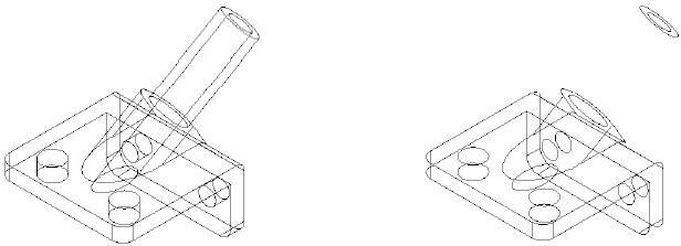
Snap tool and Solids
The Snap tool recognizes a variety of intelligent snap locations for solids. The Snap tool recognizes all hard vertices, user supplied points (grips), hole centers, cylinder centers, and fillet centers.
Vertex Cylinder Center Hole Center Solid Snaps
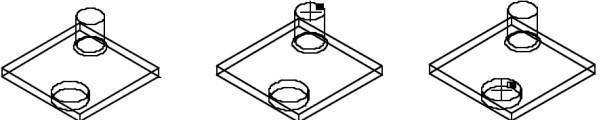
Solid Selections and Display
Solids display two types of edges. The first is called a hard edge. Hard edges are permanent edges with respect to the solid and are present in all views. The second edge type is called a silhouette edge. A silhouette edge is a temporary edge that is dependent upon the view. A silhouette edge is where the surface normal makes a perpendicular angle with the view normal.
A solid is selected by pressing the mouse on an edge or within a face. Selecting the solid by its edge is considerably faster than casting a ray to see if it pierces the solid.
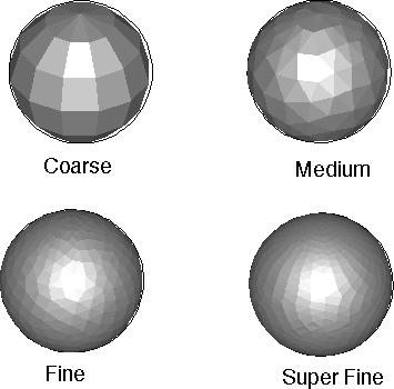
Resolution Options