Model to Sheet
TurboCAD allows you to quickly create 2D drawings from one or more curves, surfaces, and solids. The 2D drawing views are bi-directionally associative. Changes made to objects used in the Model to Sheet tool automatically update the 2D drawings. Likewise, you can use the Inspector to change parameters of the objects in the 2D drawing, and have the part automatically update. TurboCAD allows automatic creation of 2D drawings with the Model to Sheet tools located in the Main Tool Palette Menu.
Model to Sheet Overview
The Model to Sheet tool automates the process of creating drawings by the use of predefined templates. Templates are empty drawings with prearranged drawing views that are embedded within a variety of drawing borders and page formats. For example, in the Layouts folder you can find over 40 templates ranging from A-E and A0-A4 drawing sizes.
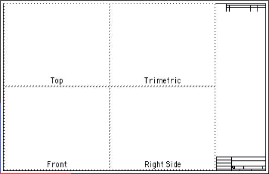
Example Template
Model to Sheet Dialog
The first step in creating a drawing is to select the objects you wish to make a drawing out of using the Arrow tool. Once the objects are selected, you can choose the Model to Sheet tool located in the Menu Bar under the Layouts option. The following dialog box will appear.
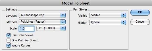
odel to Sheet Dialog
Layouts
Pressing the drop-down next to the Layouts option will provide a list of all predefined Model to Sheet templates located in the Layouts folder. The Layouts folder is found in the Install folder. All TurboCAD files in this folder are listed in the pull-down menu. You may create, modify or customize any of the templates, based upon your drawing file format preferences.
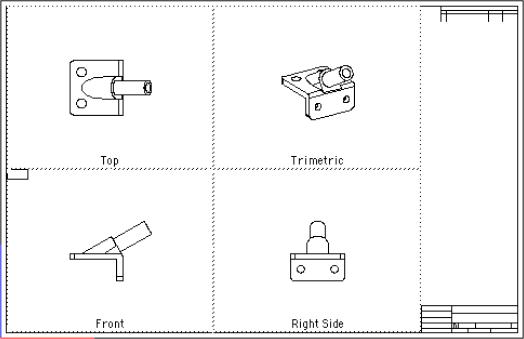
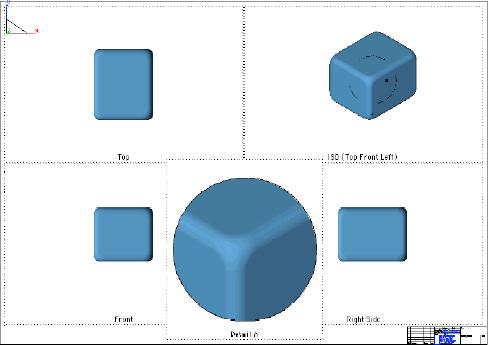
Model to Sheet Example
Method
The Model to Sheet methods determine the type of data created in each of the draw views associated with the template. The five types of methods are:
Precise
Precisely calculates the visibility of edges in a draw view. This method calculates visibility between edges and either the NURBS or analytic definition of the body. Resultant edges are lines, arcs, circles, ellipses, and splines. Precise also accurately calculates the visibility of silhouette edges.
Polyline
The Polyline method quickly calculates the visible and hidden edges by simplifying the edges into polylines and comparing its visibility with a facet representation of the body. These edges are less precise and difficult to dimension. Polylines calculate the visibility of silhouette edges as polyline segments.
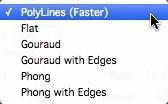
Flat
The image that appears in the draw view is generated as an OpenGL shaded image using a Flat lighting model. Because there is no vertex smoothing, you will see facet boundaries.
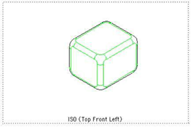
Gouraud
The image that appears in the draw view is generated as an OpenGL shaded image using a Gouraud lighting model. The Gouraud lighting model interpolates color across each facet and produces a smoother image than Flat.
Gouraud Draw Views
Phong
The image that appears in the draw view is generated as an OpenGL shaded image using a Phong lighting model. The Phong lighting model interpolates the vertex normal across each facet and produces a smoother image than Gouraud.
Phong Draw Views
Draw views, section views, and detail views can use the OpenGL methods.
Scale
This field sets the size relationship between the draw view and the sheet view. The Best Fit option will calculate a scale that fits the drawing view size.
Use Draw Views
When checked, Draw Views are created from the Model to Sheet command. Otherwise geometry is placed directly on the sheet. Draw views are required for changing the view orientation or scale as well as generating section, detail, and auxiliary views.
One Part Per Sheet
Each solid selected for Model to Sheet is placed in a separate sheet. For example, four parts will create four separate sheets. Curves and surfaces are combined into a dedicated sheet.
Ignore Curves
Curves such as lines, circles, arcs, and splines are ignored for the Model to Sheet operation.
Pen Styles
The Pen Styles option defines the line font format used by hidden and visible edges. The five options are:
Visible Attaches a predefined or user-defined pen style to visible edges. By default, the Visible pen style is used with the following attributes:
- Color Black
- Weight 0.02"
- Pattern Solid
Hidden Attaches a predefined or user-defined pen style to hidden edges. By default, the Hidden pen style is set to Ignore. Ignore tells the draw view NOT to display hidden line edges.
Holes Attaches a predefined or user-defined pen style to hole edges. A hole is defined as a hidden cylindrical surface. By default, the Hole pen style is set to Ignore. Ignore tells the draw view NOT to display hole edges.
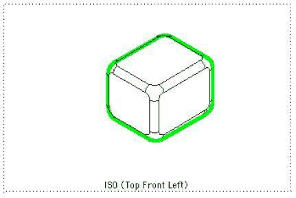
Tangent Attaches a predefined or user-defined pen style to tangent edges. A tangent edge is defined by two surfaces that share an edge with G1/G2 continuity. By default, the Tangent pen style is set to Visible.
Tangent Edges In Pen Style
Outline Attaches a predefined or user-defined pen style to outline edges. An outline edge is object profile. By default, the Outline pen style is set to Ignore.
Outline Edges In Pen Style
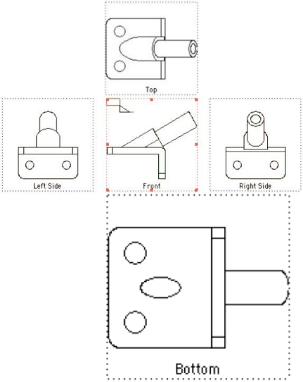
Activating Drawing Views
Once you’ve created a drawing, you can activate individual views by clicking a rectangular region surrounding the view. Once activated, the view boundaries will highlight in a red dashed border. Clicking outside will deactivate the drawing view.
When activated, all geometry in the view becomes activated. The Snap tool will now recognize all snap points in the activated view, facilitating the creation of new entities, such as dimensions. All entities created in an active view are viewed only in the view in which they were created.
Since the geometry created in the drawing views are true 2D wireframe, you may assign additional line fonts or layers to each entity.
Drawing View Menu
Drawing views have a variety of special commands accessible via a pull-down menu in the drawing view. You can access these properties by activating the view and clicking the mouse in the upper left region of the window. You may also get this dialog box by clicking the right button of your mouse. On the Mac you may click the button in conjunction with the Control key.
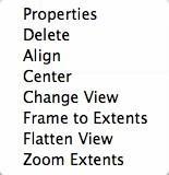
Draw View Options
Properties
Each drawing view has a set of properties and attributes that impact the draw view. These properties adjust the hidden line method, name, scale, pen styles, and other attributes described below.
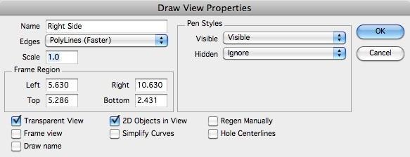
Properties Dialog Box
Name
the Name option allows you to specify the name that appears whenthe draw name checkbox is activated.
Edges
the Edges option defines the method in which hidden line edges are calculated and displayed in the view.
Scale
the Scale defines the size relationship between the drawing viewand sheet view. A sheet view is the window that contains draw views.
Frame Region
the Frame Region defines the rectangular region on the sheet viewwhere the drawing view is located.
Transparent View
Erases the background of the sheet view before drawing the drawview.
Frame View
Draws a border around the draw view.
Draw Name
Displays the draw view name centered at the lower border of theframe.
2D Objects in View
Projects the hidden line data into 2D. Circles may get projected into ellips depending on the view.
Simplify Curves
Attempts to simplify curve edges from splines to lines, arcs orcircles.
Regen Manually
When checked, the draw view is updated manually by the user. Usethe Regen View tool icon in the Sheet tools to manually update a view.
Delete
Removes the drawing view and its contents from the drawing file.
Align
The Align tool will align the active view with another selected view. You can use the Align tool on section views, general drawing views, and auxiliary views.
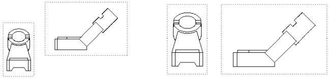
Before Align After Align Align Draw Views
Center
Centers the objects in a draw view within the frame boundaries. The scale is preserved.
Before Center After Align Center Draw View
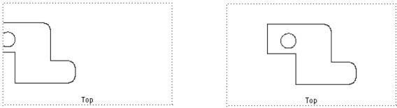
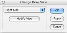
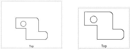
Change View
The Change View tool changes the current drawing view orientation to one of 20 predefined views or modifies the existing view by a variety of methods that include eye/ref point and rotation.
Frame to Extents
Shrinks the frame to the extents of the geometry in the view. The scale is preserved.
Frame Extents Draw View
Flatten
The Flatten option will delete the drawing view and place the objects within the view into the view containing the drawing view. The resulting objects will be scaled by the drawing view scale. This command destroys any associativity between the objects and the part that created them.
Zoom Extents
Zooms in on the geometry so that it fits to the extents of the frame. The scale is preserved.
Unfolding New Views
You can easily create new views from existing drawing views. First select the Arrow tool and activate the view you will unfold a new view from. Next, hold the Control key to indicate a copy action, then drag the view to the left, right, top or bottom. A view will be created that is the view rotated 90-degrees from the direction of the copy.
Pasting into Views
Examines the contents of the paste buffer and inserts into the active view. The inserted object is associative to the original copied object. Use this in conjunction with the New Drawing view to make drawings manually.