PhotoRender
(Available in TurboCad Pro)
The Render tool options are available from the Window menu and provide access to generation of photo realistic images to the entire screen, a selected area of the screen, to file, display previous render, and adjust advanced settings.
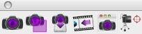
The Render Window is the first icon in the Render Palette. The tool renders the entire window. The Render Window command has a subtool palette, which includes rendering the window with the following settings:
- User Specified
- Metal
- Glass
- Plastic
- Mirror
- Wood
Render Options
The Prompt window has a pull-down option for defining certain options for rendering regarding raytracing quality and drop shadows.

These options are further defined below:
Shadows Off
This option utilizes a ray tracing algorithm that renders with shadows from objects and lights turned off. This option creates the fastest render.
Shadows On
This option utilizes a ray tracing algorithm that renders with shadows from objects and lights turned on. Turning shadows on can increase your rendering time.
Shadows Off, Anti-Alias
This option utilizes a ray tracing algorithm that renders with shadows from objects and lights turned off, but anti-alias enabled. Anti-alias samples neighboring pixels to create a smoother resultant image at the cost of increasing your rendering time.
Shadows On, Anti-Alias
This option utilizes a ray tracing algorithm that renders with shadows from objects and lights turned on and anti-alias enabled. Turning on shadows and anti-alias increases your rendering time but creates the highest quality rendering.
Drop Shadow
The Render tool has a drop-down menu that provides an option to display a shadow.
Drop Reflector
The Render tool has a drop-down menu that provides an option to display a reflection on the floor.
Drop shadow and reflector
The Render tool has a drop-down menu that provides an option to display a shadow and reflector in a single menu.
The “shadow off” modes achieve fast image rendering speeds by skipping the scene's shadow calculations. The shadow “on modes” do produce shadows in the image at the expense of processing time. The Raytraced Render (shadows on, Anti-Alias) mode is intended for final image generation. It uses all the accuracy of ray tracing in combination with anti-alias over-sampling. The computation time is significantly longer, but the end result is very impressive.
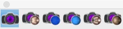
Rapid Render Environments
The Render Window tool also supports five Rapid Render Environments. Use the Rapid Render Environments to easily and immediately create stunning images from your models. These are preset rendering environments that automatically set up lighting, environment maps, and materials. The five Rapid Render Environments are Metal, Glass, Plastic, Mirror, and Wood.
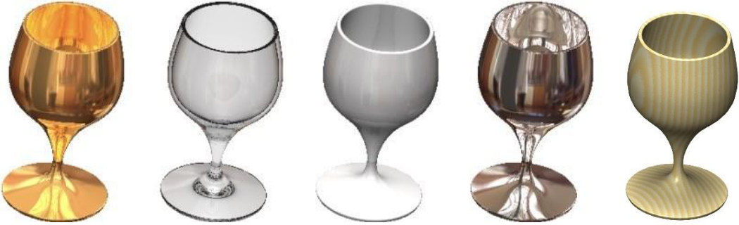
Metal Glass Plastic Mirror Wood
* *RapidRender Environments
Render Area
The Render Area tool allows you to select an area of the window to render. The Render Area tool uses the user specified materials to generate an image.
Render to File
While rendering to a window is sufficient for proof of image and informal viewing, publication quality images require a resolution (>300 dpi) that far exceeds the resolution of a typical computer monitor (~90 dpi). The generation of high-resolution images is controlled by the Render to File dialog box. This dialog is displayed using the Render: Render to File… menu option.
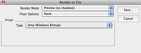
Render to File
The Render Mode drop-down list specifies which of the 6 modes is used for image generation. These match the modes described in the Rendering to a Window section above.
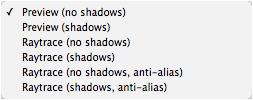
Render Modes
The Floor Options drop-down provides options for including shadows and reflectors in the rendering.
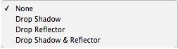
Floor Options
The Image section sets the output limits for the image file. The Type drop-down list specifies the format of the generated image file. The Width and Height values specify the image size in pixels. If the Match Width/Height to Drawing Aspect is checked, the width and height will be automatically synchronized such that image's width-to-height ratio will be equal to the drawing window's width-to-height ratio. If the Match Width/Height to Drawing Aspect is unchecked, any appropriate values may be entered.
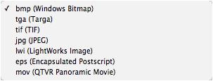
There are seven image format types supported: Windows bitmap (bmp), Targa (tga), TIFF (tif), JPEG (jpg), Lightworks image (lwi), Encapsulated postscript (eps), QTVR Panoramic Movie (mov)
Show Last Image
Displays to the drawing window the last rendered image.
Render Settings
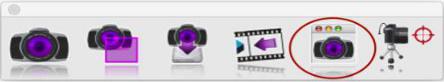
The Render Settings tool icon displays a dialog box with useful parameters associated with rendering.
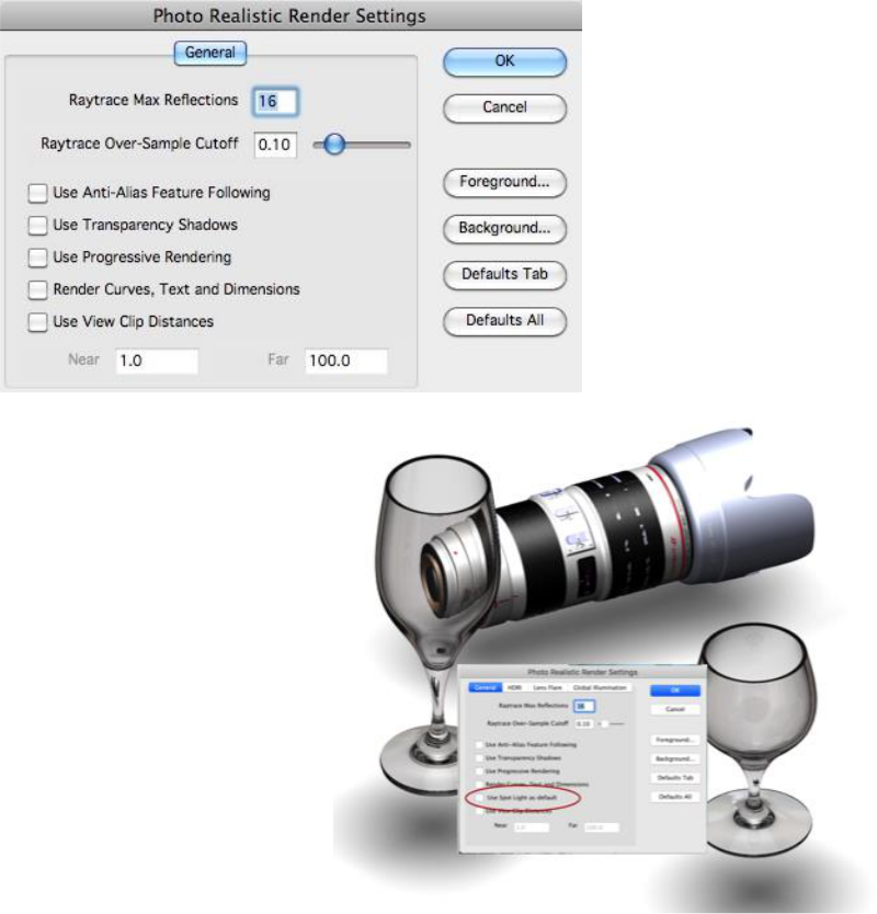
PhotoRender SpotLight
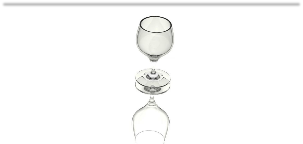
The default PhotoRendering method uses a distant light offset from the viewing direction that creates an image suitable for most conditions.
The new “Use Spot Light as Default” option calculates a spot light with a cone angle directly above the rendered objects. Combined with a floor, soft shadows are created below the objects providing an alternative to the default.
The new option is accessed from the PhotoRender tool palette Settings option.
Use Spot Light as Default
Multiple Processor Rendering
TurboCad Pro supports multiple processors when using the photo rendering command on Mac OSX. Additional processors are automatically enabled if you have a dual-processor Mac.
Environment Maps
A key to generating eye-popping images is placing an object in an environment or scene that will reflect realistically back onto the object. A very fast way to obtain this effect is to use a specially constructed image that projects onto the objects in a scene. These are called environment maps, which are supported in TurboCad Pro through an easy to use drag and drop interface.
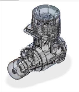
Environment maps are especially effective with reflective surfaces such as metals. In the example below the same scene is rendered with and without an environment map.
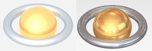
(a) Without Environment Map(b) With Environment Map
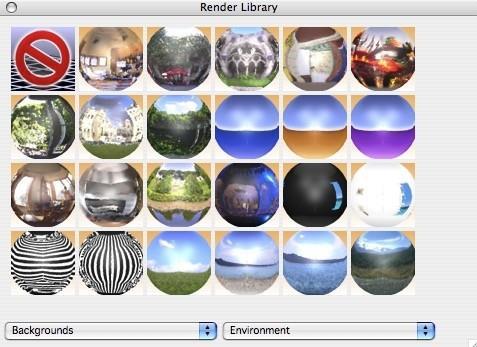
Background Environment Shaders
Environment maps are implemented in TurboCad Pro as Background Shaders. To access a background shader, display the Render Materials Dialog and select the Backgrounds option in the pull-down menu. Next select the Environment shaders. Drag and drop any of these shaders to the background to add an environment map to your rendered image.
Chrome and Gold Materials
Camera Object
This tool creates a camera object saved as geometry, within the model. Use a camera object to store a location, direction, and field of view. The camera object is located as the last item in the photo- rendering tool palett
A camera object is created by specifying the camera eye and reference point. Use the Data Entry window to specify a field of view. To activate a camera, right click on the camera symbol to display the menu.
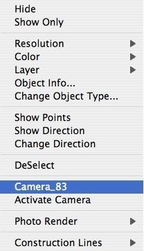
Select the Activate Camera to change the view orientation to that specified by the camera.
The Render to File tool also recognizes cameras. To render multiple view orientations, create the cameras and have them selected prior to picking the Render to File tool.