Prompt Window
The Prompt Window displays a brief description of what the application is expecting you to do for the current command. In addition to the prompt string, it displays a large detailed tool icon, the tool name, tool hints, and help information. To the right of the prompt strings you will find the data entry fields, and to the far right are the screen coordinates of the cursor.

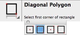
Additional Tool Options
Some tools contain additional options. The presence of these options is indicated by an arrow in the large icon, left of the tool name. By default, the additional tool palette will display just below the prompt. If the additional tool palette has been closed, it will remain closed until you click on the arrow located in the large image icon. Drag to the left to keep the palette open permanently.
Tool Hints
To the right of the tool name in the prompt window are Tool Hints. Tool Hints display additional information regarding the current command. Hints may contain tool options controlled by hitting the Control or Apple keys as well as tips for using the tool.
In the above prompt window, the tool hints provide the following additional information regarding the
Selection tool:
-
Pressing the Shift key will add or subtract entities to theselection.
-
Pressing the Option key will copy selected objects if clicked and dragged.
-
Selecting from right to left will select any entity that crosses the select box.
Data Entry Fields
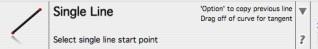
Whenever you select a tool from the Tool palette, the Data Entry Fields appear in the center of the Prompt Window. The data entry fields display numerical values related to the current tool. For example, when the Single Line tool is selected, the Data Entry Fields contain values for the X, Y, and Z coordinates of the beginning point and the Length and Angle values for the line.

You can use the Data Entry Fields in three ways:
To create an object with keyboard entries only.
To edit an object that was just created and is still selected. To create an additional object using the current tool.
Whenever you construct an object, the data entry field containing the specification that you are most likely to change is preselected (the box is highlighted). For example, when you draw a line with the Single Line tool, the Length box is highlighted so you can enter a value for the length. You do not have to move your cursor to activate entries into the pre-selected field. Just type in a value from the keyboard and it will enter it into the highlighted entry field. Press the Return key to accept the entry.
If you want to make an entry in a different field, you can use one of four selection methods:
-
Press the Tab key to activate and cycle the selection highlight through the status boxes from left to right.
-
Click inside the status box and the pointer allows you to edit text.
-
Double-click inside the status box to select the entire contents of the box.
-
Click the box label to select the entire contents of the box.
In addition, selected fields support cutting and pasting into and out of other fields.
Expression Parsing
The Data Entry Fields boxes also accept various mathematical, trigonometric, and exponential operators. Position the cursor in the text field and type in the additional operation. The expression parser handles decimals, integers, and fractions, all with units. Equation parsing is also supported in all dialog box fields that are looking for numeric inputs. The expression syntax is as follows:
expression: value [binaryop value]
value: [+|-] {literal | param | const | macro |[(] expression [)]}
binaryop: {+ | - | * | / | ^ | %}
literal: {integer[unitspec] | float[unitspec] | fraction}
float: {integer {. |,} integer | {. |,} integer} [{even} [+|-]
integer] fraction: [integer {unit spec} [integer {unit spec} ...]] [simplefrac] simplefrac:[integer] [ integer/integer[unitspec]]
unitspec: {y | yd | yds | yards | f | ft | feet | ' | i | in | inch | inchs | inches | " | millimeters | millimeter | mm | centimeters | centimeter | cm | decimeters | decimeter | dm | meters | meter | m | pts | pt | p}
param: alphas[integer]
const: {pi}
macro: macroname(expression)
macroname: {sin | cos | tan | asin | acos | atan | sinr | cosr | tanr | asinr | acosr | atanr | abs | ceiling | ceil | dtor | exp | floor | factorial | fact | log | ln | neg | round | rtod | rnd | sqrt | truncate | trunc | sqr | cube | odd | even | sign}
| integer: | {0... | 9} [{0 | ...9} ...] |
|---|---|---|---|
| alphas: | {a... | z | A... | Z} [{a. z | A. |
| Z} ...] where, | |||
| [X] | Optional component where X is a list of components separated by a “|” char | ||
| {X} | Mandatory component where X is a list of components separated by a“|” char | ||
| X... | X is repeated any number of times | ||
| X... Y | Component shorthand for all ASCII chars from X to Yinclusive |
Examples of supported expressions are listed below:
| Operator | Example | Operator | Example |
|---|---|---|---|
| Addition | 3+.450 | Arctangent | atan (1.0) |
| Subtraction | 3-.500 | Log Base 10 | log (7.25) |
| Multiplication | 3*.725 | Natural Log | ln (8.5) |
| Division | 3/5.25 | Remove | truncate |
| Square Root | sqrt (8.75) | Absolute Value | abs (-47+16) |
| Parenthetical | 3/ (5*2/4) | Smallest Larger | ceiling (5.25) |
| Scientific | 4e-3 | Largest Smaller | floor (12.75) |
| Exponentiation | exp (2.7) | Negative Value | neg (1.12) |
| Sine of Angle | sin (15) | Round | round (1.12) |
| Cosine of Angle | cos (30) | Fraction | 1 1/2 + 3/4 |
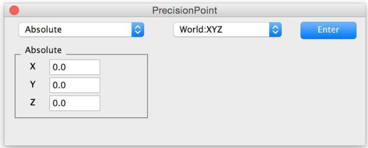
PrecisionPoint
The PrecisionPoint icon appears to the right of the Data Entry fields. The PrecisionPoint tool provides a means to rapidly enter explicit data to create and modify geometry. Options include data entry using absolute XYZ coordinates, relative coordinates, distance along entity, and percent along entity. This is a helpful option for creating entries according to specific coordinates or moving existing entities in certain positions.
Methods
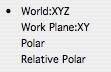
There are four methods of entering coordinates using PrecisionPoint.
World: XYZ Enter xyz data in the world coordinate system.
Work Plane: XY Enter xy data relative to the current work plane.
Polar Enter data in a polar coordinate system.
Relative Polar Enter polar data relative to a vector/angle.
Absolute
Coordinates that are entered are relative to the origin (0,0).
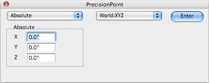
Using the Absolute option, you can specify the coordinate system:
-
World XYZ - Based on XYZ coordinates.
-
Work Plane XY - Based on XY coordinates.
-
Polar - The entity’s coordinates are based on a specified distance and angle, from the origin.
Relative
Coordinates that are entered are relative to the last point picked. The last point data will be displayed, and you have the option to specify different coordinates by clicking at a new position or entering new values.
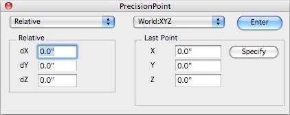
Using the Relative option, you can specify the coordinate system:
-
World XYZ - Based on XYZ coordinates.
-
Work Plane XY - Based on XY coordinates.
-
Polar - The entity’s coordinates are based on a specified distance and angle, from the last point.
-
Relative Polar - Specify the two points from which you want an entity placed, then enter the distance and angle.
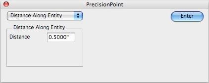
Distance Along Entity
Allows you to specify the distance from an existing point that an entity is placed. As you move your cursor along an existing entity, it snaps to the distance that has been specified.
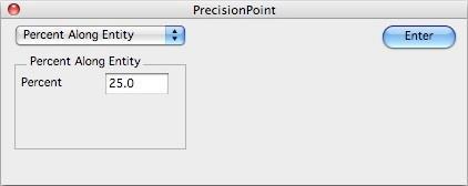
Percent Along Entity
Allows you to specify at what percentage of an existing entity to draw or place a point. As you move your cursor along an existing entity, it snaps to the percentage that has been specified.
Percent Along Entity
Allows you to specify at what percentage of an existing entity to draw or place a point. As you move your cursor along an existing entity, it snaps to the percentage that has been specified.