3D Printing Tools
(Available in TurboCAD Deluxe and TurboCAD Pro Only)
The 3D Print palette provide a collection of tools to check and prepare a part for 3D Printing. The nine tools are:
- 3D Print Check
- Surface Normals Check
- Overhang Analysis
- Wall Thickness Analysis
- Preview Slices
- Auto Position
- Support Structure
- Show Print Volume
- Printer Definitions
3D Print Check
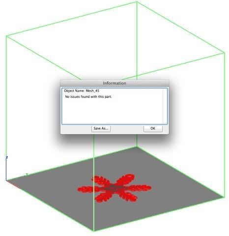
The 3D Print Check tool checks a part for its print viability, displaying warnings or errors to the user. The checks include:
Position Check
The position check examines the extents of the part and verifies that the part is within the positive x, y, z coordinate system. Use the Auto Position tool to automatically position the part within the positive coordinate system.
Facet Count Check
Some 3D printing service bureaus, cannot process more than 1,000,000 facets. If you have more than 1,000,000 facets you may need to reduce the number of facets in your model.
Size Check
- If your model is too large or too small for standard 3D printers, a warning message is displayed.
- The too small message warning is displayed if the model is less than 0.3 x 0.3 x 0.3 cm.
Closed and Water Tight Check
A 3D printer must have a closed volume to print. If your model is detected to have open edges an Error alert is displayed.
Duplicated Facets
This check examines each facet as unique in the model. If it finds another facet at the same position, an Error message is displayed.
Collapsed Facets
A collapsed facet has no area. This check will inform you if the part has zero area facets.
Normals Check
Facet normals define the inside and outside areas of your part. If some of your facet normals are pointing the wrong way, the 3D Printer may have problems creating the part.
Manifold Check
Some solid modeling programs allow you to create non-manifold solids. A manifold part has exactly two facets connected to each edge. If an edge has one facet attached, then the edge is open and is detected by the Closed Water Tight Check. However, it is possible for a model to have more than two facets connected to an edge. This check isolates those types of edges and reports an error.
Example: 3D Print Check
- Select the print definitions from the Printer menu.
- Press the Exit button to close out the dialog with the selectedsettings.

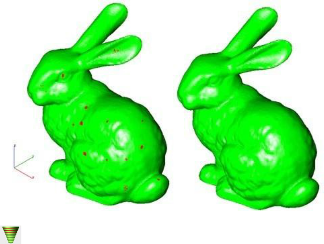
Surface Normals Check
The Surface Normals Check performs a visual analysis of a part's surface normals. Facets displayed green have correct facet orientation whereas red represent an improperly defined facet normal. 3D Printing must have normals pointing away from the material.
Example: Surface Normals Check
- Select the Surface Normals Check tool.
- Select any command to exit.
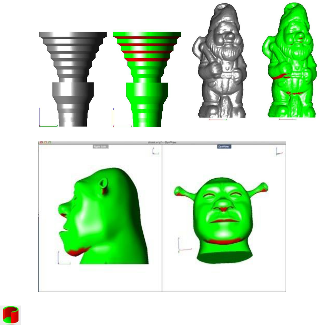
Overhang Analysis
The Overhang Analysis tool provides a means to visually inspect model areas that may require structural support for 3D printing. Meshes, surfaces, and solids facets normals are compared to the work plane direction. Angles that are less or equal to 45 degrees are highlighted as red. Overhangs can still be printed if you apply appropriate support structure. To add support structure to an overhang, use the Support Structure tool.
Example: Overhang Analysis
- Select the Overhang Analysis tool from the tool palette.
- Select any command to exit.
The drawing window is updated showing red or green areas where red areas indicate a potential overhang issue.
Wall Thickness Analysis
The Wall Thickness Analysis tool provides a means to visually inspect modeling areas that may be too thin for 3D printing. Meshes, surfaces, and solids facets are examined using ray intersections clearances.
Example: Wall Thickness Analysis
- Select the Wall Thickness Analysis from the tool palette.
- Select any command to exit.
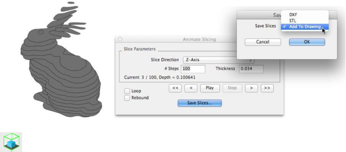
Preview Slices
The Preview Slices tool provides a user interface to slice models given a direction and thickness. The dialog box allows for animation through the slices as well as single stepping. One use of the Preview Slice tool is to verify a part has closed, non-overlapping sections, a requirement for 3D printing.
Slice Direction
Defines the cut direction for slicing. For 3D Printing use the Z-Axis. For examining sections such as fuselage stations, use the X-Axis.
#Steps
Defines the number of slices through as function of the extents of the part.
Thickness
Specify the distance between steps as a thickness.
Loop
Continue looping through the slicing when the fore and aft extents are reached.
Rebound
After reaching the last step, start backwards from the current position.
Play
Start viewing slices.
Save Slices
The Save Slices… option provides several options to save slices to DXF, STL or add the results directly into the drawing.
Example: Preview Slices
- Select the Preview Slices command from the tool palette.
- Specify the number of steps or thickness.
- Press the Play button.
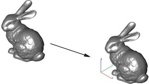
Auto Position
The Auto Position tool positions a collection of parts within the boundaries of the default print platform.
Centered
The selected parts are translated to the center of the print platform.
Align from Facet
The selected part is rotated and translated to the print platform center. The selected facet is used to align the part to the print platform.
Optimal Packing
The selected parts are distributed on the print platform such that the available space is optimally used.
Example 1: Centered
- Select Auto Position from the tool palette.
- Select the Centered option from the pull-down menu.
- Select the objects to center.
- The objects are translated to the center of the default print platform.
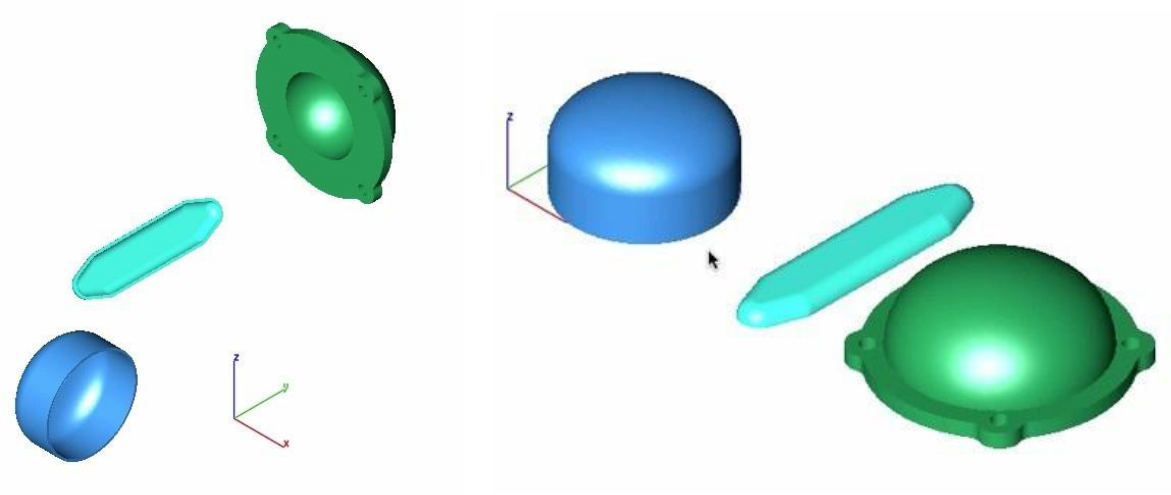
Example 2: Align from Facet
- Select Auto Position from the tool palette.
- Select the Align from Facet option from the pull-down menu.
- Select the facet to align to the printer platform.
- The objects are rotated and translated to the center of the default print.
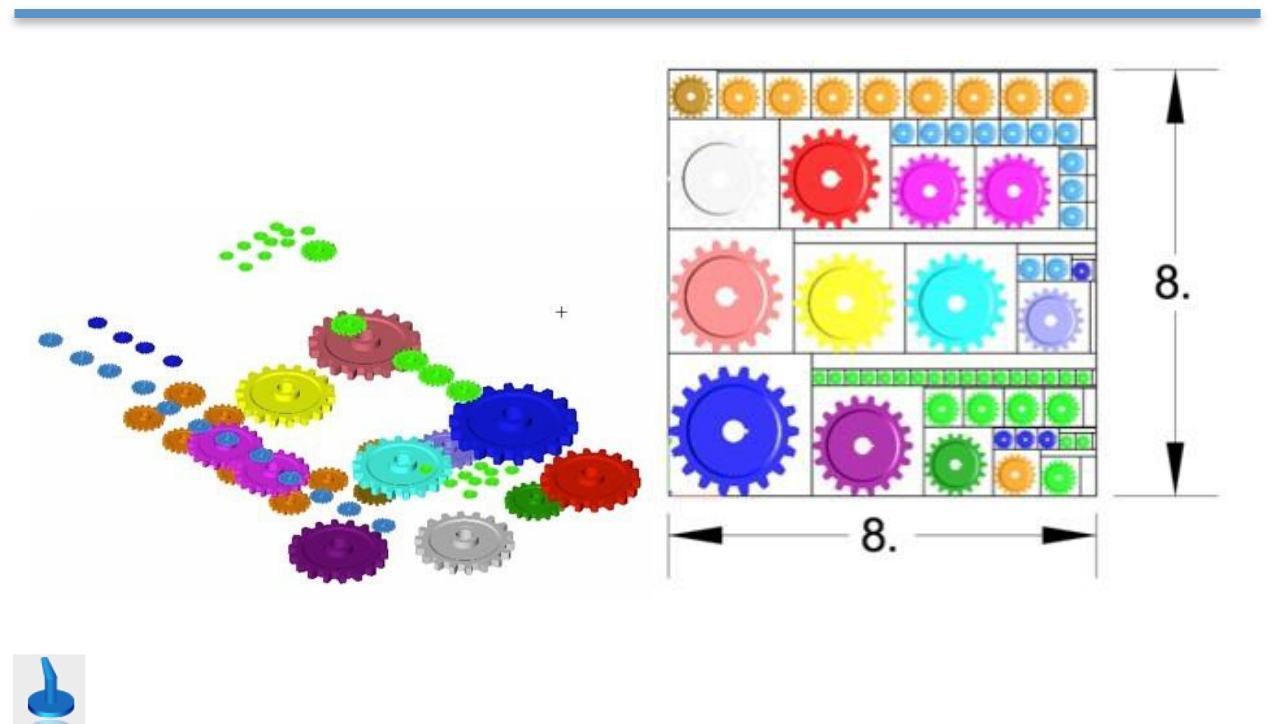
Example 3: Optimal Packing
- Select Auto Position from the tool palette.
- Select the Optimal Packing option from the pull-downmenu.
- Select the objects to translate to the printer platform.
- The objects are translated into place within the boundaries of the specified print platform.
Support Structure
The Support Structure provides a tool that manually adds geometry to support material. Support structures controls include:
Attach Radius
Midpoint Radius
Base Radius
Base Thickness
Drag base and mid points to modify structure location
Example: Support Structure
-
Select Support Structure from the tool palette.
-
Specify location for starting point on the mesh.

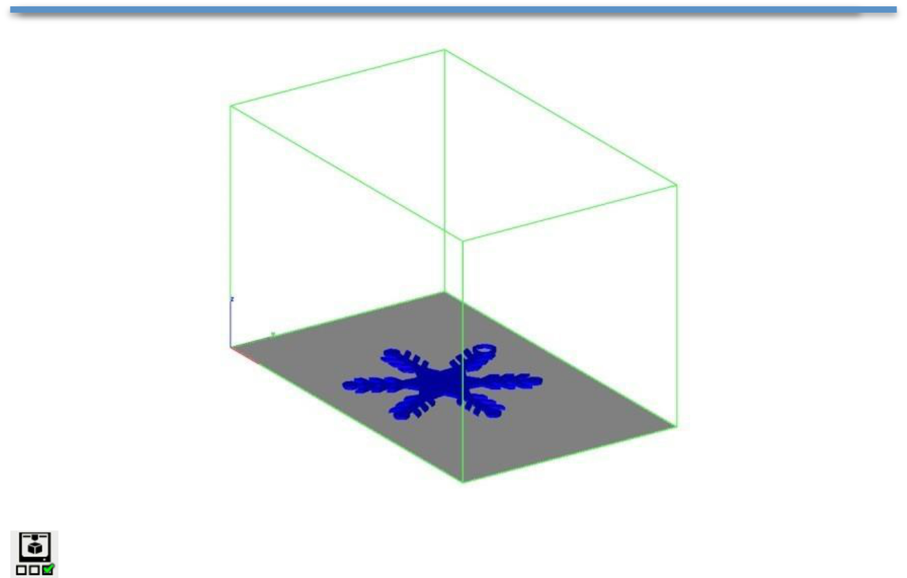
Show Print Volume
Toggles the boundary of the default 3D Printer. The volume is defined within the Printer Definitions dialog box.
Example: Show Print Volume
- Select a 3D Printer definition from the Printer Definitions dialog box.
- Select the Show Print Volume to display graphically the volume with the part.
Printer Definitions
The Printer Definitions dialog box provides a means to set key parameters of the 3D printer. Theparameters include the length, width, and height of the volume accessible by the printer. The parametersin the Printer Definitions dialog box are used for commands such as 3D Print Check and AutoPosition. To show the Printer Build Volume, select the "Show Print Volume" option. This will display agraphically volume representing the printable volume for the given printer.
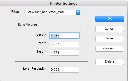
Printer Select a printer definition file already defined from amenu.
Length The maximum length along x accessible by the printer.
Width The maximum width along y accessible by the printer.
Height The maximum height along z accessible by the printer.
Layer Resolution The height between print layers.
Save Change the current settings to the Printer.
Save As Change the settings and Save As a new printer definition.
Delete Remove the existing Printer from the menu.
Example: Set the default 3D Printer
- Select the print definitions from the Printer menu.
- Press the Exit button to close out the dialog with the selected settings.