PhotoRender Settings
The Photo Realistic Render Settings dialog box controls general render, HDRI, Lens Flare, and Global Illumination settings. To access the Photo Realistic Render Settings dialog box, click the Render Settings tool from the PhotoRender toolset.
General Settings
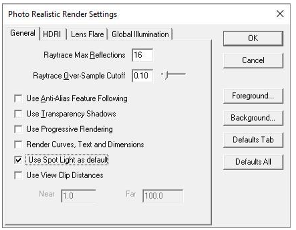
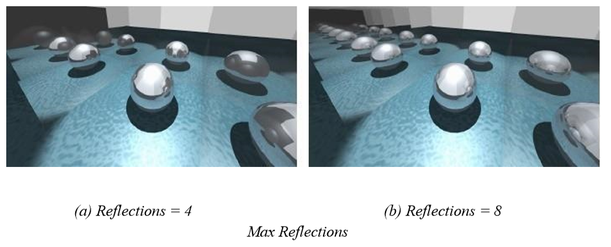
Raytrace Max Reflections
The Raytrace Max Reflections value controls the maximum number of “bounces” a ray will be allowed to make. Once a ray has reached this limit, no further color calculations will occur for that ray. The images of a mirror-walled room below demonstrate the effect of changes in the Raytrace Max Reflections value.
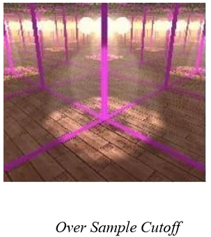
Raytrace Over-Sample Cutoff
The Raytrace Over-Sample Cutoff value controls the threshold for adaptive image over-sampling. The image will be sampled until adjacent color samples differ in the largest of their red, green, and blue components by an amount not exceeding the Raytrace Over-Sample Cutoff value. The valid range is from 0.0 to 1.0. The default value is 0.1.
Use Anti-Alias Feature Following
The Use Anti-Alias Feature Following (AAFF) checkbox controls the application of AAFF. If checked, a second pass will be made over an image that brings out small geometric feature details that may have been lost due to ray sample aliasing.
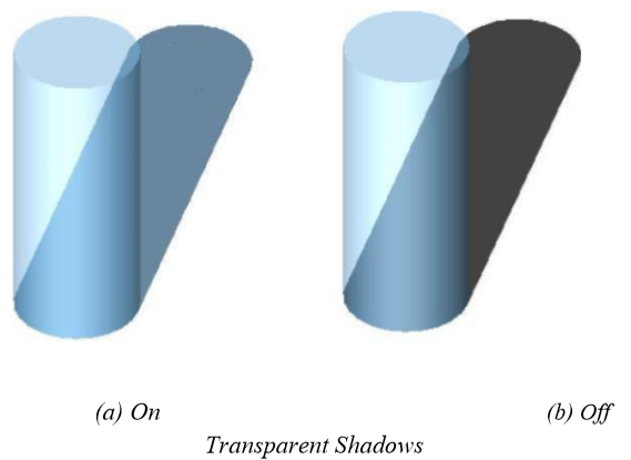
Use Transparency Shadows
The Use Transparency Shadows checkbox controls the behavior of shadow generation for transparent objects. If checked, the shadow cast through a transparent object uses the object color. If not checked, the transparent object will cast an opaque shadow.
Use Progressive Rendering
Progressive Rendering provides immediate feedback of a final image with a fast preview of the lighting and materials in a scene; it provides users with a way to get a desired image with less iteration.
Render Curves, Text, and Dimensions
This option enables photorealistic rendering of curves, text, and dimension entities. Use this feature to add annotations to a final rendered image.
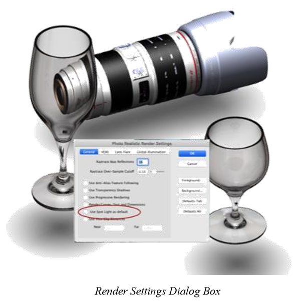
PhotoRender SpotLight
The default PhotoRendering method uses a distant light offset from the viewing direction that creates an image suitable for most conditions.
The “Use Spot Light as Default” option calculates a spot light with a cone angle directly above the rendered objects. Combined with a floor, soft shadows are created below the objects providing an alternative to the default.
The option is accessed from the PhotoRender tool palette Settings opt
Use View Clip Distances
The Use View Clip Distances checkbox and the Near and Far values control the near and far clipping plane behavior. The near and far clipping planes are normal to the view vector and are at the specified distance from the eye point. Any objects (or portions of objects) that lie aft of the far clipping plane and forward of the near clipping plane are ignored for the image. As implied, an object can be “sliced” if it is intersected by a clipping plane.
If Use View Clip Distances is checked, the Near and Far distance values are used for the clipping plane distances. If Use View Clip Distances is unchecked, the near and far clipping planes will be automatically set to the near and far view extents of the model (all objects are rendered for the image). Unless you are trying to achieve a particular result, Use View Clip Distances should normally be left unchecked.
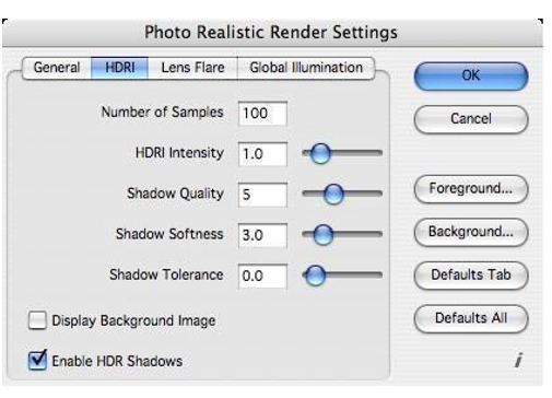
HDR Render Settings
The HDRI tab of the Photo Realistic Render Settings dialog box provides controls for changing the intensity, shadow quality and other settings for HDR rendering.
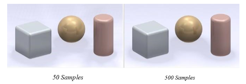
Number of Samples
The quality of lighting decides how good the lighting seen on objects will correspond to the environment. It depends mostly on the "number of samples", i.e., the number of lights used to simulate environment lighting. The more samples used, the more accurate the lighting. On the other hand, increasing the number of samples makes rendering longer.
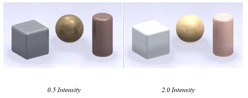
HDRI Intensity
The HDRI intensity parameter decides the strength of the lights which are lighting a scene and the overall brightness of the rendered image. Typically you will want to match brightness of lit objects with the brightness of the environment (for example, if the environment is bright, objects lit by it should be bright also). Choosing a value which will make lit objects match the background requires experimentation.
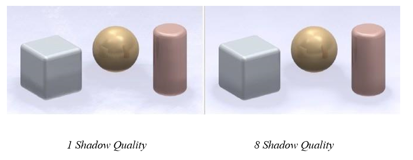
Shadow Quality
Increases the quality of shadows at the cost of rendering time.
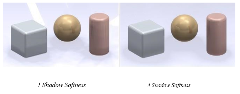
Shadow Softness
Determines how soft the boundaries of shadows appear.
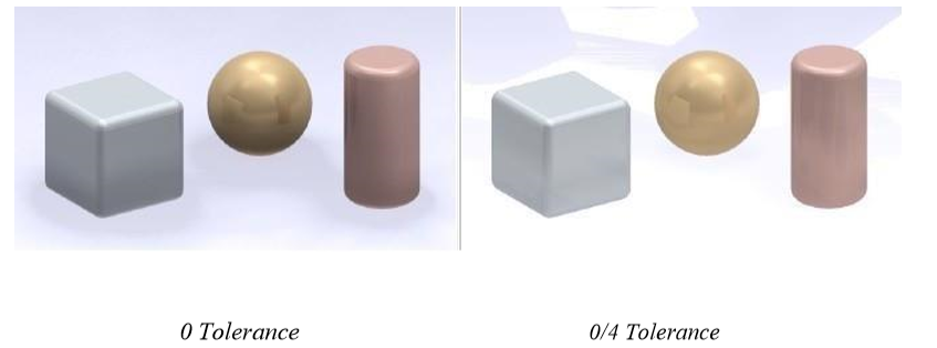
Shadow Tolerance
Modifies the shadow map sampling distance. It is used to deal with self-shadowing artifacts that can be apparent with low resolution, high softness shadows. They usually appear as either grid-like patterns of smudges or moiré patterns. A value of 0.0 specifies no effect; a value of 1.0 causes no shadows. Values around 0.1 to 0.2 are usually sufficient to deal with most artifacts. The value of this parameter should be as small as possible, because large values can cause shadows to disappear from objects close to the object casting the shadow. A value of 1.0 will cause all shadows to vanish.
HDRI Map Type
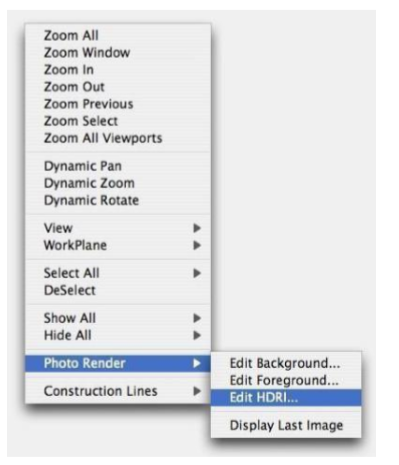
The HDRI Setting dialog controls the HDRI Map Type. To access the dialog, right-click the design window and choose Edit HDRI from the PhotoRender menu.
There are seven options available on the drop-down menu.
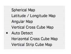
Spherical Map
Usually created by photographing a reflective sphere with a telephoto lens.
Latitude/Longitude Map
Sometimes known as a panorama, where the entire environment is flattened into a single, flat panoramic image, rather like a map of the globe.
Angular Map
Sometimes known as a “light probe” image. It is similar to a spherical map from a reflective sphere, except the radial dimension is mapped linearly with the angle, instead of being pushed towards the edge of the circle. This gives a more accurate sampling around the edges of the image.
Vertical Cross Cube Map
A cubic map created by reading a single image, which consists of six sub-images laid out in the form of an unfolded cube.
Auto Detect
This examines the image data for solid black areas and decides on the type, depending on the pattern made by the areas of black. It is, therefore, capable of correctly distinguishing the following types of images only: angular, horizontal cross cube, vertical cross cube, and latitude/longitude.
Horizontal Cross Cube Map
A cubic map created by reading a single image, which consists of six sub images laid out in the form of an unfolded cube.
Vertical Strip Cube Map
A cubic map created by reading a single image, which consists of six sub images laid out flat into a single image in 1:6 aspect ratio, consisting of 1 by 6 square sub-images representing the cube.
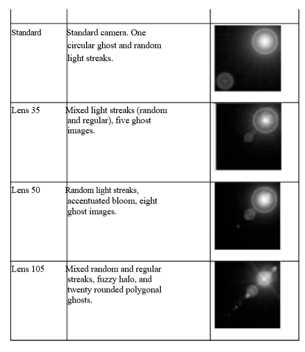
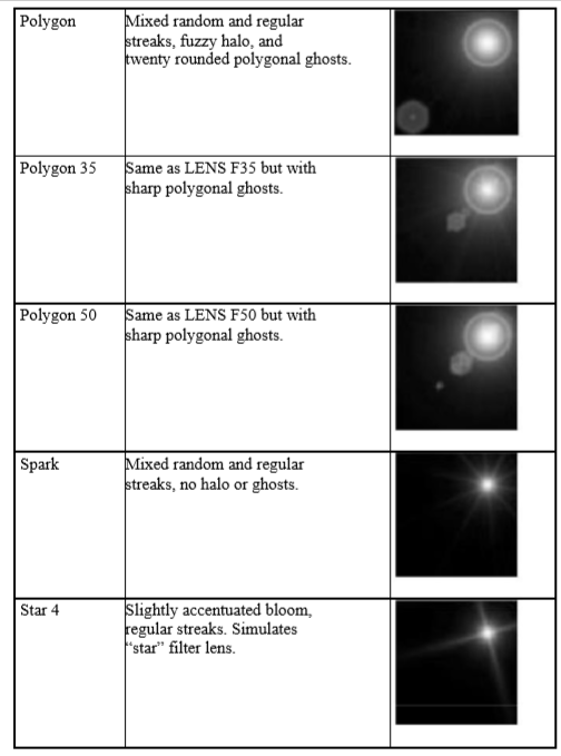
Lens Flare Settings
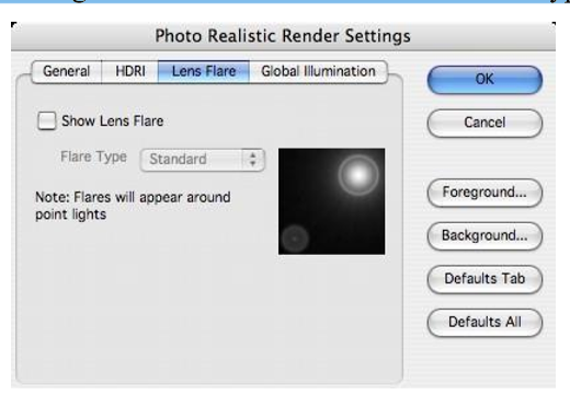
Access to Lens Flare settings is available under the PhotoRendering Settings dialog box, Lens Flare Tab. Options available include turning on or off the lens flare and lens flare types.
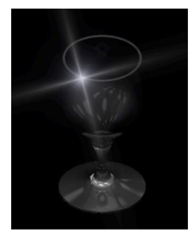
central area of glow
random and regular streaks of light
halos around light sources
ghost images of the lens iris
The main components of such effects may be circular, polygonal or polygonal with rounded edges, depending on the shape of the camera’s iris. Although such effects might be thought of as a side-effect of the design of real life cameras, they are often used by photographers and cinematographers to produce pleasing visual effects.
SharkCAD simulates lens flare effects as an image post-processing effect. To enable Lens Flare effects, display the Photo Realistic Render Settings dialog box and turn on the “Show Lens Flare” checkbox. The scene will render normally, then render once more adding in the lens effect.
Show Lens Flare
This checkbox enables post processing of Point Light types as Lens Flare effects.
Global Illumination Settings
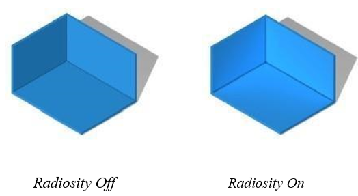
Global Illumination is a lighting method used to evaluate the distribution of all the light energy in an environment. This feature is enabled through the Photo Realistic Rendering Settings dialog box.
The final rendering solution that is generated encapsulates the light distribution throughout the scene, accounting for all diffuse interreflections, and is independent of any particular viewpoint. Simpler rendering techniques (non-global illumination) attempt to approximate the effect of diffusely reflected light in a scene by applying a constant “ambient” value of illumination throughout the entire scene.
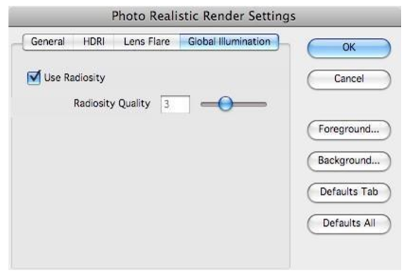
Radiosity is essentially a technique that correctly computes the distribution of this “ambient” light,
accounting for light reaching a surface after being reflected from one or more diffuse surfaces. To enable this feature, click on the Global Illumination tab and Use Radiosity checkbox.
The quality settings is a natural number, lying in the range 0-9, which is used to set groups of internal control variables such as shadow quality and sampling. The default value is 2, with 0 indicating low quality and 9 indicating a very high quality.
Note: Enabling radiosity can significantly increase rendering times.
Edit Foreground
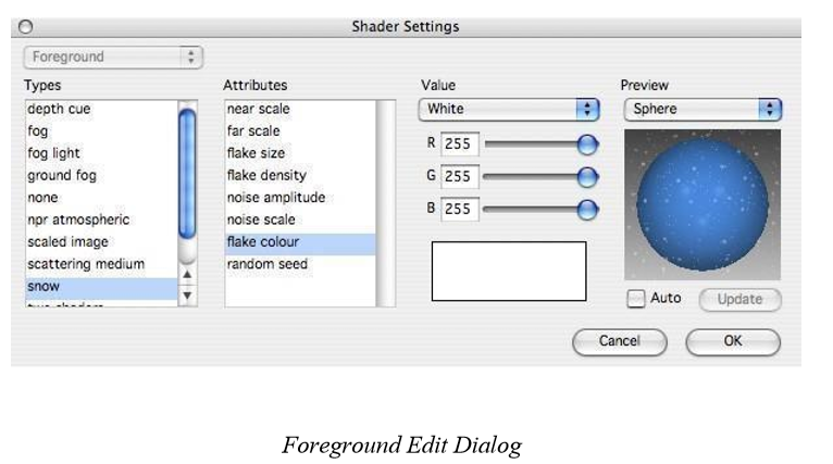
The Edit Foreground menu option displays a dialog box that allows editing of the foreground used in the Render commands. You can access the Foreground Shader Settings from the Render Setting dialog or from the right-click menu.
The dialog box has the same familiar interface of the Advanced Material editor which consists of Shader Types, Attributes, and Attribute values.
Below is a list of the Foreground shader types and associated descriptions.
depthcue A foreground shader that adds a background color specified by parameter “background color” according to the distance of the surface from the viewer. At distances less than that given as “near”, no background color is added. At distances greater than “far”, the full background color is returned. Between the two distances, the output is linearly interpolated between the surface and background colors. The effect is that depth information in the geometry is enhanced in the final image.
fog A foreground shader that implements atmospheric absorption to create a ‘fog’ effect. The contribution made by the fog whose color is given by “fog color”, is attenuated asymptotically using the formulation: 1 - e^{-d} where d is the distance of the shading point divided by the reference distance supplied as “distance”. Increasing this value advances the fog further from the viewer.The density of the fog is clamped to a maximum value specified by parameter “max density”. By default this value is 1.0. Values between 0.0 and 1.0 are sensible – values less than zero will be interpreted as zero and values greater than one will be interpreted as one. The fog effect can be enabled or disabled for background pixels using “ignore background”. By default this is set to TRUE, i.e., there is no fog effect applied to background pixels.
foglight Atmospheric scattering from point and spot light sources. A constant distribution of particles in the atmosphere is assumed. The light fall-off used in the scattering computations is 1/d^2, so light sources tend to look saturated near their center. Light sources should therefore also use a 1/d^2 type fall-off for consistency between atmospheric and surface shading. Also note that spot lights should have an almost constant angular intensity distribution (i.e., a hard-edged illumination cone). Volumetric shadows are not implemented by this shader.
grndfog This shader is used to create more subtle fog like effects than the standard “fog” shader. With this shader the fog density decreases exponentially along a user specified axis. The parameter “fog height” sets the rate of decrease (if this is set to zero or a negative value, the effect is the same as with the standard “fog” shader).
The parameters “ground point” and “ground normal” define the place where the fog lies. It is assumed to be the plane z=0 by default.
Note that fog does not exist at all below the ground plane, so in the default case there is only fog in the z>0 halfspace.
The density of the fog is clamped to a maximum value specified by parameter “max density”. By default this value is 1.0. Values between 0.0 and 1.0 are sensible – values less than zero will be interpreted as zero and values greater than one will be interpreted as one.
The fog effect can be enabled or disabled for background pixels using “ignore background”. By default this is set to TRUE, i.e., there is no fog effect applied to background pixels.
noneforeground No foreground. Pixel values are output unmodified.
scatteringmedium This shader enables simulation of a full range of effects occurring in a participating medium, including: attenuation within medium light filtration through colored medium first order light scattering inside medium with volumetric shadows The light scattering effects are modeled for all light shaders except “ambient”, “eye” and “sky” (though are available in “area sky” shader). The “first order scattering” mentioned above means that the shader visualizes direct effect of scattering in medium – scattered light coming to observer but does not consider secondary effects – multiple bounces of light within the medium or illumination of surfaces by scattered light.
The shader performs attenuation of original surface color according to given medium attenuation coefficient and medium color. As one could expect, the longer distance from shaded point the dimmer and more colored by medium it becomes. In addition to attenuation it is also possible to specify medium ambient light scattering which gives overall veiling effect. Finally the shader models scattered light from all the supported light sources if “scattering” parameter of the source is set to TRUE.
snow A foreground shader that gives the effect of snowflakes falling in front of the camera. The effect is produced by two overlaid planes of randomly dispersed “snowflakes”. The scale of each of the two planes is specified by the parameters “near scale” and “far scale”. The size and density of the flakes is given by the parameters “flake size” and “flake density”, and the irregular appearance of the edges of the flakes is controlled by the “noise amplitude” and “noise scale” parameters (these last two values should lie in the range 0.0 to 1.0). The color of the snowflakes is specified by the parameter “flake color”. Finally, it is possible to change the distribution of the snowflakes from the default by changing the “random seed” parameter. This provides an initial seed value for the random distribution.
Edit Background
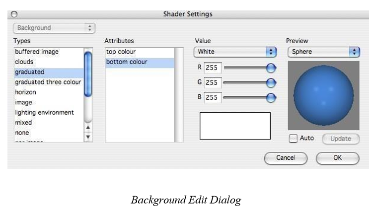
The Edit Background menu option displays a dialog box that allows editing of the background used in the Render commands. You can access the Foreground Shader Settings from the Render Setting dialog or from the right-click menu.
The dialog box has the same familiar interface of the Advanced Material editor which consists of Shader Types, Attributes, and Attribute values
Below is a list of the Background shader types and associated descriptions.
cloudsbackground A background giving a cloudy appearance. The color of the clouds and the background (sky) may be specified in arguments “clouds color” and “background color”, respectively. The detail or complexity of the texture may be controlled by means of the “detail” argument. A value of 1 will give a simple outline of the clouds, while a larger value such as 5 or 6 will give fine detail on the cloud outlines. An overall scaling factor is provided in argument “scale”; increasing this value will make the clouds appear larger.
envmapbackground When this background shader is used, the current global environment map is sampled at background pixels.
The “intensity” argument allows the ‘brilliance’ of the reflection to be altered†– the color value calculated for each pixel of background is multiplied by the intensity value. The “angle” specifies the angle, in radians, over which the environment map is sampled for each pixel of background. This allows the environment map to be “blurred” slightly. By default the value is 0.0, meaning that the color of each pixel is established from a single point sample taken through the center of the pixel.
graduated A background providing a graduation from the top of the image to the bottom of the two colors specified as arguments “top color” and “bottom color”, respectively.
horizon The horizon is shader providers a simple horizon with a graduated sky and ground colors.
image A background shader that maps an image.
The name of the file containing the image data may be provided as a string to parameter “file name”, which can be in any format for which the appropriate image driver is installed.
mixed A background shader which mixes the results of two other background shaders (“base shader” and “mixed shader”) according to the ratio given as parameter “mixing ratio”.
nonebackground No background. Regions of the image not covered by any surface will appear black.
plainbackground A plain background with a single, uniform color. The color is supplied in argument “color”.
raycube A problem with ordinary background shaders is that they don’t handle
reflections or refractions. This is because all pixels at which the background is deemed to be visible are shaded in the same way, using a background which is located only in image space, rather than in real 3D space. Thus, for example, a mirror, which should reflect the background behind the viewer, in fact shows the background exactly as it would be if the mirror were not there (i.e. all the mirrors become transparent). This would even be the case if the mirror has geometry behind it, so the effect becomes one of a hole in the geometry. This shader allows two other background shaders to be used, one for the areas of background directly visible to the viewer, and another for reflections. Thus the “primary shader” is used for primary rays which do not intersect any geometry, and the “secondary shader” for reflection rays which do not intersect any further geometry (i.e., reach the background).
“Reflected shader” or “refracted shader” allow background shaders to be specified for reflected and refracted rays. If either is defined then it will be used in preference to any “secondary shader” that is specified. The “refracted shader” also applies to any rays that have passed through a transparent medium. If either of the shaders is not defined, then black is used as the default background color. A situation where this shader is very useful for rendering images where the directly visible background is supposed to be replaced in post- production. The environment background would be used for reflections, and the plain background for the directly visible background, which can then be replaced by an image. This may be useful when producing animations.
scaledimage A background of an image read from a file, and scaled to fit into the viewport.
The image may also be rotated.
twoplanes This shader allows two background images to be located in world space (one
in front of the observer and one behind). These images can then be ‘reflected’ in any mirrors, thus producing the correct effect (refraction is also correctly handled).