Draw
The Draw Menu provides additional construction methods for creating new geometry such as lines, circles, splines, and surfaces.
Line Bisector
Circle Normal To Curve
Average Two Curves
Curve From Two Views
Best Fit Plane
Surface Grid
Shadow Projections
Unroll Surface
Gear
Line Bisector
The Line Bisector command creates a line that bisects at a specified angle using four-point locations.
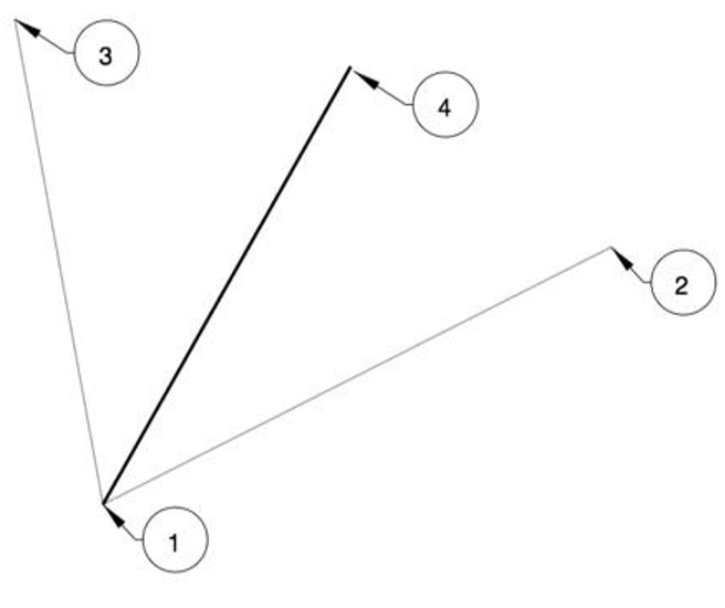
Example:
- Select the Line Bisector command.
- Pick the start of the bisector line, shown by label 1 in the above figure.
- Pick the start of the angle to bisect, as shown by label 2 in the above figure.
- Pick the end of the angle to bisect, as shown by label 3 in the above figure.
- Pick the end of the end of the line, as shown by label 4 in the above figure. This location defines the length of the line.
Circle Normal To Curve
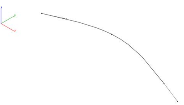
This tool constructs a circle normal to a curve at a specified location.
Example:
- Select the Circle Normal to Curve tool.
- Specify a location for the circle center along the curve.
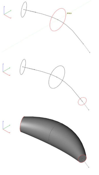
- Move cursor to set the circle diameter. Use the data entry window to set precise diameter.
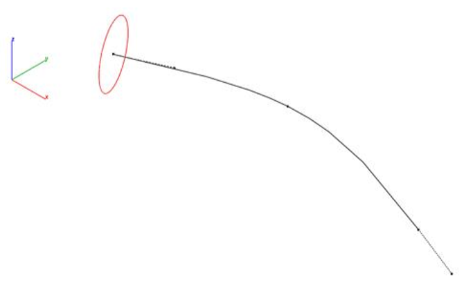
- As an example use, the circles can be used as a profile of skinned solid.
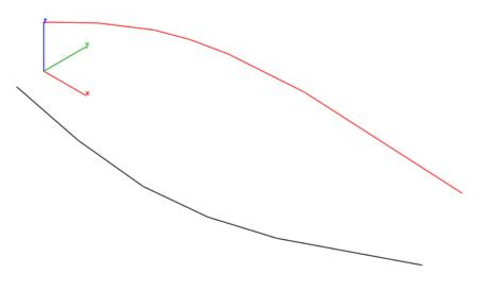
Average Two Curves
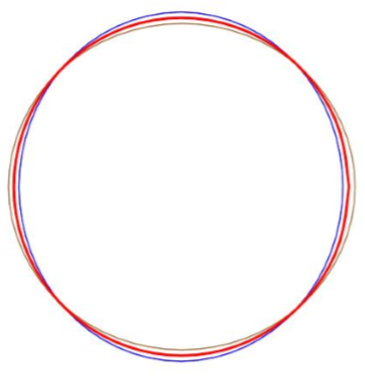
The Average Two Curves command takes as input two curves and averages the closest between to create a third curve.
Example:
- Select the Average Two Curves command.
- Select two curves.
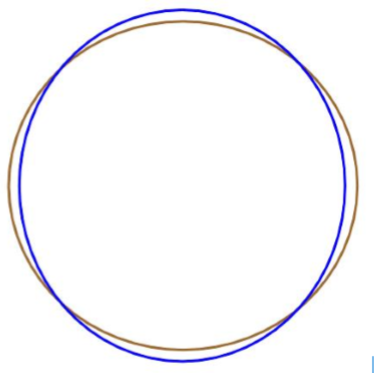
- A curve is created that is the average to the two selected curves. In the image below, the red curve is the average of the blue and brown input curves.
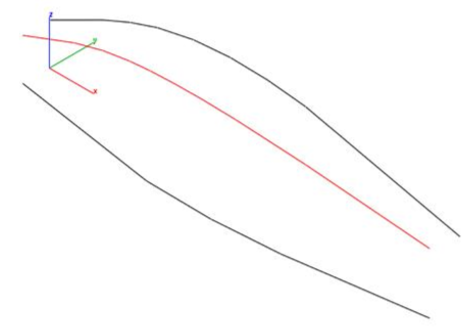
Curve From Two Views
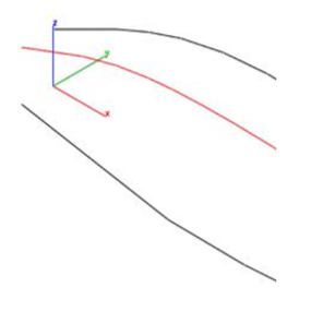
The Curve, Normal to Two Views tool projects creates a curve by the intersection of two projected curves.
Example:
- Select the Curve, Normal to Two Views.
- Select the first curve for first projection.
- Select the second curve for second projection.
- Specify start point for first projection direction.
- Specify end point for first projection direction.
- Specify start point for second projection direction.
- Specify end point for second projection direction.
- A spline is created at the intersection of the two projected curves.
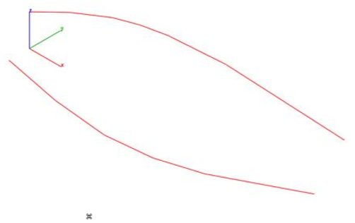
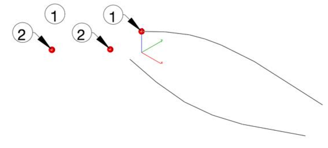
Best Fit Plane
The Best Fit Plane tool calculates an infinite plane object from a collection of supplying 3D points.
Example:
- Select the Best Fit Plane tool.
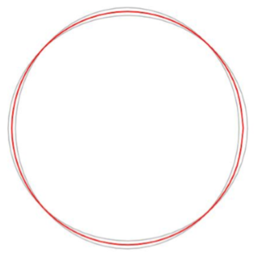
- Pick 3D points for best plane fit. Seen as red spheres for this example.
- The Infinite plane object is created from the data.
- An example use is shown below where the plane is used to project the curves into a common plane.
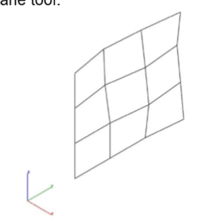
Surface Grid
The Surface Grid creates a NURB surface from either a reference surface or by specifying two diagonals.
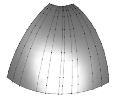
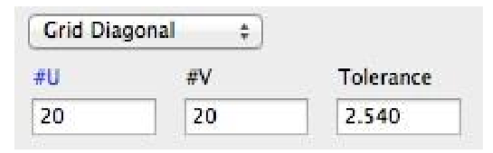
Data Entry Values:
#U Number of grid points along the u direction
#V Number of grid points along the v direction
Tolerance The tolerance between the grid points and resulting surface.
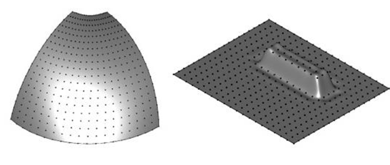
Example1: Grid By Reference Surface
- Select the Surface Grid command.
- Select Reference Surface from the pull down menu.
- Specify the grid settings.
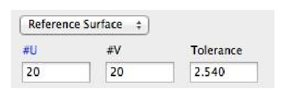
- Select a reference face or surface.
- Select a reference face or surface. A new surface is created with the specified grid settings.
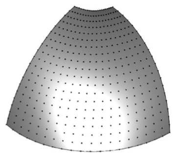
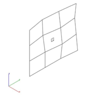
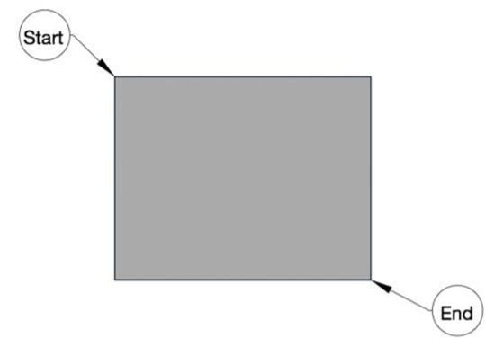
Example 2: Grid By Diagonals
- Select the Surface Grid command.
- Select Reference Surface from the pull-down menu.
- Specify the grid settings.
- Select start diagonal.
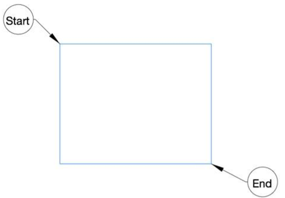
- Select end diagonal.
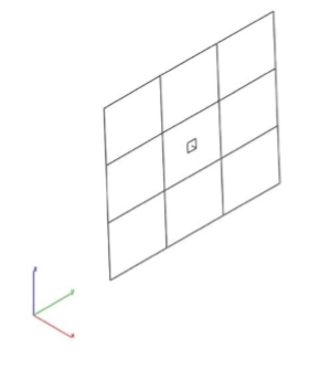
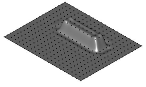
- A surface grid is created between the diagonals.
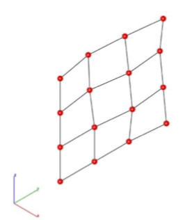
- Display and edit the grid points by turning on Edit: Show Points.
Shadow Projections
The Shadow Projection command projects a solid outline into a plane. Select xy, yz, xz, or workplace as the plane to project the outline into.
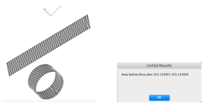
Unroll Surface
This tool flattens the meshes and unrolls ruled surfaces.
Example
- Select the unroll surface tool from PowerPack > Draw
- Select the developable surface which you want to unroll/unfold
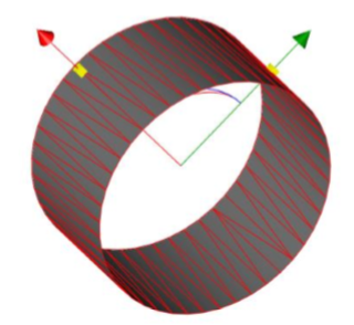
- After selecting, the surface will be unrolled/flattened. A window will appear which will show unfold results, e.g. Area before / Area after unfolding/unrolling.
Gear:
This tool creates spur gear by defining its properties. User can enter a custom value to get the gear model according to the requirement.
Example
- Select the gear tool from PowerPack > Draw
- Enter the requirements in the fields, which are:
• Number Teeth
• Module
• Pressure Angle
• Cone Angle
• Clearance
• Involute Samples
• Hole Radius
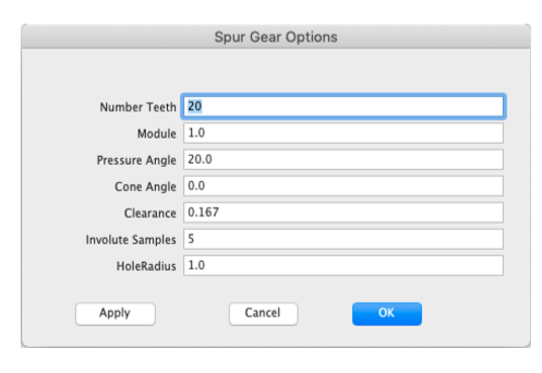
- Click apply button to create a gear model.
