Drawing in 2D
Home Design Studio provides many options for looking at your design onscreen. You can display several windows, each containing a different view of your plan. This gives you the flexibility to view your drawing as a 2D plan, as a 2D with a corresponding 3D view, or using only Punch! 3D View.
When viewing your 2D home plan, you can magnify the view by zooming in, reduce the view by zooming out or pan the view in any direction. 3D viewing provides many options, from walking through the home plan to flying around the plan or viewing the framing or completion phase of your project. You can adjust 3D display settings using a variety of viewing features, including adding shadows, for a realistic effect, or adjusting the lighting intensity of the view. Finally, you can create a photo-realistic view of your design.
2D Drawing Methods
There are some common 2D drawing methods that you’ll use repeatedly while creating your design in Punch! Below are detailed steps for each of the drawing methods. Practice these methods before you begin, or refer back to this information as you draw. If a tool requires a different drawing method, it is explained where the tool is described.
Click Once to Place
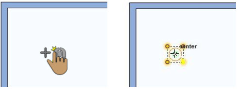
This method is used for items that do not attach to a walls, like columns, floor and ceiling receptacles, fixture lights, furnaces, and other items that are positioned freely in a design.
To draw using Click Once to Place
■ Position your cursor where you want the selection to be placed and click your left mouse button. The selection is placed at the location you click.
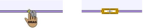
Drag-to-Size
This method is used for items like walls, roofs, pre-defined shapes (rectangle, circle/oval, line, arc, multigon), and other shapes that are based on a user-defined size. For details on controlling the automatic dimensions display, see “Dimensioning”.
To draw using Drag-to-Size
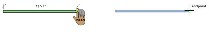
■ Position the cursor at the start point for the shape, then hold down the left mouse button and drag from the start point to the desired length. A rubber band line is displayed as you drag. Release to place.
Define 2D Shape
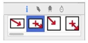
This method is used for manually drawn shapes like floors, decks, railings, and more. The draw methods become available on the Properties pane when a tool that uses this method is active. Each Draw Method button shows an example of how the shape is drawn.
To draw using Define 2D Shape
1 When a tool that uses Define 2D Shape is active, the draw methods become available on the Properties pane.
2 Choose the shape and method you want for the active tool.
3 Draw the shape based on the method you chose. For detailed steps to draw shapes and lines, see the following sections:
■ “Drawing Rectangles and Squares”
■ “Drawing Circles and Ovals”
■ “Drawing Lines”
■ “Drawing Polygons”
■ “Drawing Arcs”
■ “Drawing Circular Arcs”
■ “Drawing Multigons”
■ “Drawing Curves”
Drag Along Wall
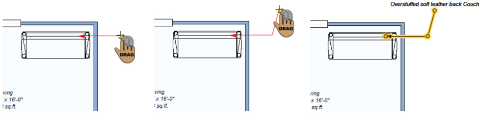
This method is used for wall attachments such as windows, doors, receptacles, and more. As wall attachments, objects remain attached to the wall even if the wall is moved.
To draw using Drag Along Wall
■ Drag along a wall, release to place on the side where you want it.
2D Editing Methods
There are some common editing methods that you’ll use repeatedly while creating your design in Punch! Below are detailed steps for each of the editing methods. Practice these methods before you begin, or refer back to this information as you draw. For additional editing techniques, see the chapter titled “Edit Your Design”.
Reshaping and Resizing 2D Objects
Objects created using the Drag-to-Size or Define 2D Shape drawing method can be reshaped or resized by dragging a point or segment. For information on how to lock segment angles or release snaps and alignment constraints, see “AutoSnap and Alignment Options”.
To reshape and resize 2D objects1 Click the Select Objects  button and then click to select the point or segment you want to edit.
2 Drag the selection to reshape or resize the object. Release to place. Elevating Objects
You can adjust the elevation of an individual object or a group of objects to a specific value or to match the elevation of a nearby object. You can also elevate all of the objects on an entire floor. For more information, see “Elevating Objects”.
Component Description
Components that are added to your design from one of the plan tab have a default description you can change. The description text is used in the Description column in Estimator. In the example below, the Kitchen Cart name is displayed for editing.
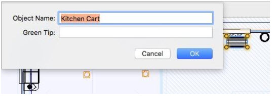
Updates to the description text only affect the component in your plan; changes do not affect the original item in the content library. To edit the component description information in the library, copy the item to the User Library and then edit its details. For more information, see “Organizing Library Content”.
To edit component description
1 Choose the Select Objects button from the Editing Tools group and then right-click the object and choose Object Information from the shortcut menu.
2 Edit the text as needed and click OK.
Using the Grid
With Home Design Studio you can set specific grid properties that aid in drawing your home plan. You can set points, based on the reference grid, which is useful when you want to make sure certain points are placed precisely.
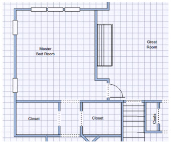
Grid settings have a direct impact on the ease of aligning objects, snapping objects to the grid. When using the Snap to Grid feature, items that are dragged and dropped on the design window are automatically snapped, or placed, to align with the current grid. By default, Snap to Grid is on. You can customize grid settings by selecting grid spacing, grid style, and hiding or displaying the minor grid lines.
To display the grid
■ While nothing is selected in the design window, click the Properties tab  and select the “Display Grid” checkbox.
To hide the grid, deselect the checkbox.
(alternatively) Choose 2D > Show Grid. To hide the grid, choose Hide Grid from the menu.
To move objects/features along the grid
1 Choose the Select Objects  button from the Editing Tools group.
2 Click to select the object you want to move.
3 Press the arrow keys on your keyboard to move the object into position.
Note: Each time you press an arrow key, the selection moves one increment that you have set in the Snap Grid settings.
To enable or disable Snap to Grid
When snap to grid is enabled, you can use the grid lines (and minor grid lines) as a reference to move selections based on those lines. Selections move based on the Snap Grid settings, which you can control by editing the grid settings (see “To configure grid settings”).
■ While nothing is selected in the design window, click the Properties tab  and select the “Snap objects to grid” checkbox.
To disable snap to grid, deselect the checkbox.
■ Choose 2D > Snap to Grid. The feature is enabled when a checkmark is visible and disabled when a checkmark is not visible.
To configure grid settings
1 Choose 2D > Grid Properties. (alternatively) Right-click the design window and choose Grid Properties from the shortcut menu.
2 Edit the grid settings and then click OK. Style specifies whether the grid uses lines or dots.
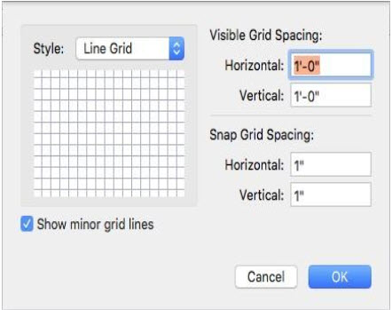
Note: Grid Dots/Lines can be set to as low as 1 inch (English), 0.02 m (Metric), and still be viewable. Grid Dots/Lines can be set as high as 500 inches (English), 12.70 m (Metric).
Visible Grid Spacing defines the horizontal and vertical measurements for the grid. This is the distance between each grid line/dot.
Note: Initially, the grid is set at 12" for English and .03m for Metric, making it easy to visualize each plan square as exactly one square foot, but can be customized to meet your particular design needs.
Show minor grid lines checkbox controls the display of the snap grid.
Snap Grid Spacing defines the horizontal and vertical measurements for the minor grid lines. Items you draw or drag into the design window snap to the measurements you’ve defined here.
Note: Snap settings can be set as low as 0.0625 (1/16 inch) English, 0.01 meter (1 cm) Metric, and still show visible movement along the grid. Snap settings can be set as high as 500 inches (English), 12.70 meters (Metric).
AutoSnap and Alignment Options
Snap points are automatically enabled as you design. Snap points are designated points or “hot spots” where your cursor can lock-in, for help with accurate placement. Laser alignment is also available for easily aligning segments as you draw. Laser alignment and auto snaps can be enabled or disabled from the Preferences window.
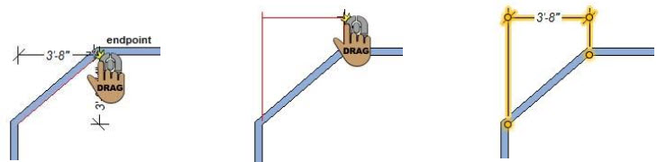
Auto Snaps
By default, when snap points are enabled, the midpoint and endpoints appear when your pointer reaches these points. You can control these, and other “hot spots” or points, to which your pointer snaps in the Preferences dialog, which is available in the Home Design Studio menu.
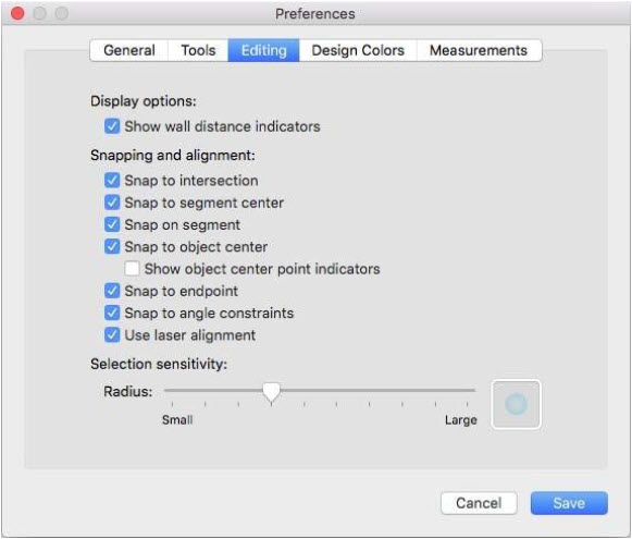
To control automatic snaps
1 Choose Home Design Studio > Preferences (or press Command-Comma (,). The Preferences dialog appears.
2 Click the Editing tab to access the snap options.
3 Under Snapping and alignment, select or deselect the snap points you want and then click Save.
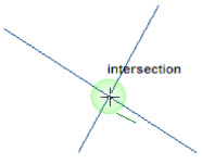
Intersection displays the intersection of two lines.
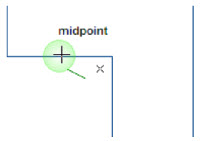
Segment Center displays the center point along a segment, as you drag.
On segment displays when the crosshair is actively on a segment as you drag.
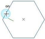
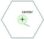
Object Center displays the center of an object as you drag to place within its bounds. A useful example would be centering a lamp on a table.
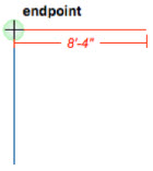
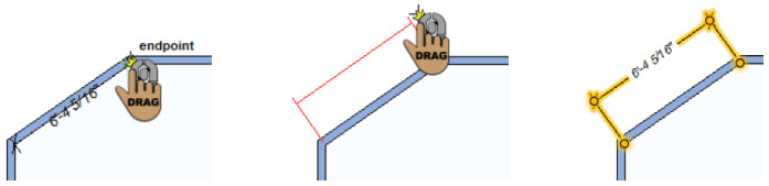
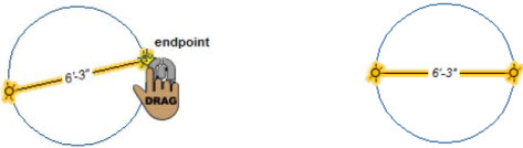
Endpoint displays the endpoint of an object as you drag to place within its bounds. useful example would be drawing walls.
Snap to angle constraints snaps the cursor in 5-degree increments when drawing segments at an angle. While this snap constraint is enabled you can use keyboard shortcuts to override this constraint or lock a segment at an angle.
■ Hold the Shift key while drawing to disable snap points and laser alignment
■ Hold the Command key to lock a segment angle while dragging

Selection Sensitivity Snap detection radius controls the size of the snap point detection area. To configure the selection sensitivity radius, drag the slider to decrease or increase the radius.
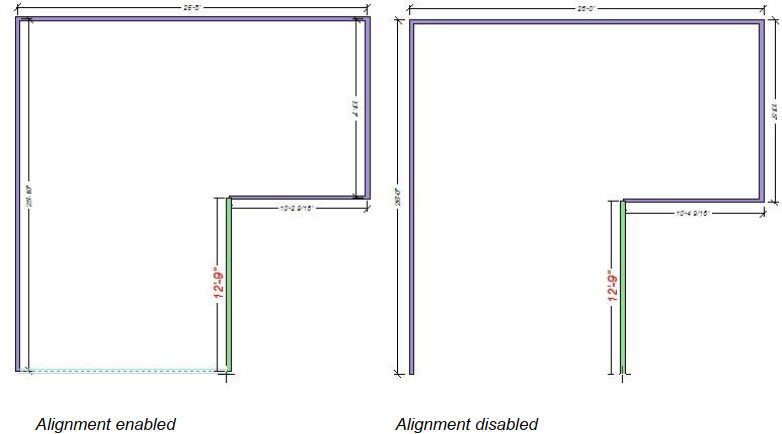
Laser Alignment
In addition to snap points, you can control the laser alignment that appears when your pointer is in alignment with an existing point, as you are dragging. In the example below, the cursor is positioned at the bottom of the drawing, where two end points align. When the cursor is positioned at one of the end points and laser alignment is enabled, the alignment is displayed.
To control laser alignment
1 Choose Home Design Studio > Preferences (or press Command-Comma (,). The Preferences dialog appears.
2 Click the Editing tab to access the snap options.
3 Select the “Use lase alignment” checkbox to enable the laser line, or deselect to disable, and then click Save.
Text Font
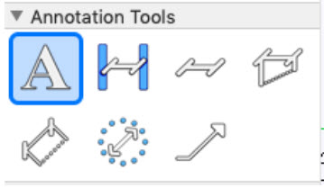
Use text to add information to your drawing. For example, you might add text to annotate rooms, specify a home address, the date the drawing was created, or a specific feature in your plan. Home Design Studio gives you the flexibility to place text anywhere in your plan drawing, using different formatting techniques for each text instance. The text you place in your drawing appears on all 2D printed output. The text tools are available in the Annotations Tools group on the left sidebar. For information on assessing the sidebar, see “Left Sidebar”.
Rich Text Tool
Using the Rich Text tool, you can add multi-lines with different fonts using multiple sizes, rotation angles, and attributes in a single text object. You can customize the text color, transparency, or assign a drawing style to the bounding box such as a background fill and pattern to your design for annotations. When adding text, you can edit the font properties by clicking the Font button, or edit the font after the text is placed. For more information, see “Edit Text and Text Properties”.
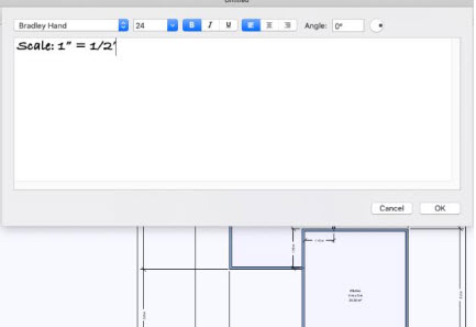
To place text in your drawing
1 Choose the Rich Text  button from the Annotation Tools group and then click in the design window where you want to place text. A dialog appears.
2 Enter the annotation in the field. Press the Return key to move to the next line.
3 Click OK to place the text.
Rotated Text
Using the Rotated Text tool, you can add a single line of text at an angle for precise annotations. When adding text, you can edit the font properties by clicking the Font button, or edit the font after the text is placed. For details on font settings, see “Edit Text and Text Properties”.
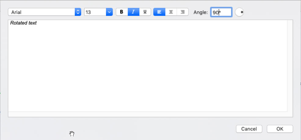
To place text at an angle
1 Choose the Rich Text button from the Annotation Tools group and then click in the design window where you want to place text. A dialog appears.
2 Enter the annotation in the field. Press the Return key to move to the next line.
3 Enter the Rotation Angle you want or drag the dial to set the angle.
4 Click OK to place the text.
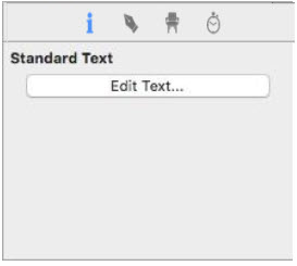
Edit Text and Text Properties
Once you’ve added text in your drawing you can edit the content, font properties, and alignment.
■ Select the text and click the Edit Text button on the Properties pane (or right-click the text you want to edit and choose Edit Text from the shortcut menu). The text appears in a dialog.
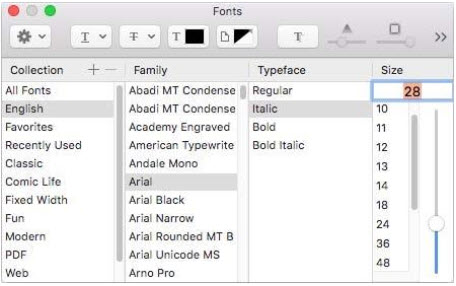
■ Choose the Fonts button and change the font, style, and size. To narrow the font options, choose the Collection and Family you want. The available fonts appear in the Typeface column.
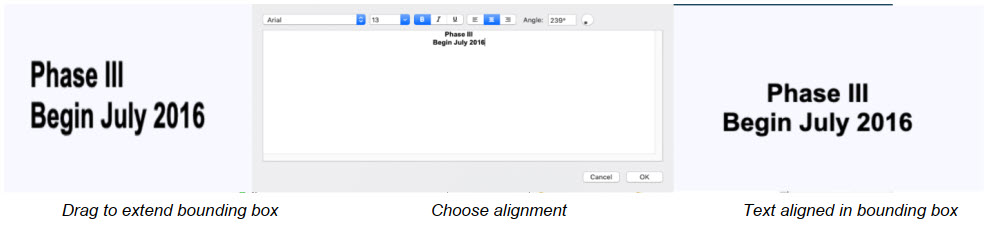
■ Alignment allows you to set the text justification for Left, Center, or Right (only available for multi-line text). Alignment is positioned within the text’s bounding text box. To resize the bounding box, drag a corner point to set the size and then select the text alignment style you want and click OK
Dimensioning
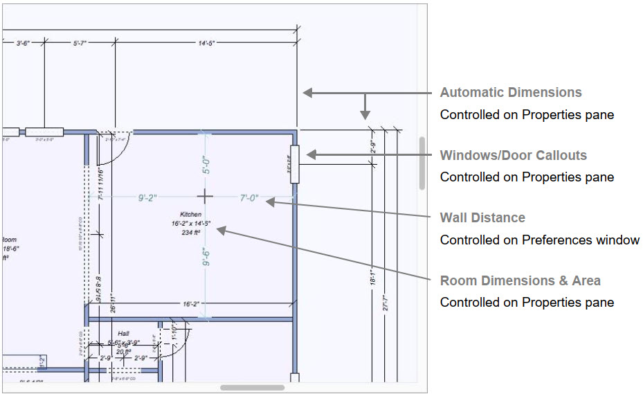
Home Design Studio automatically displays dimensions as you draw, making it easy to precisely place walls, doors, and other items in your plan drawing. This includes automatic dimensions, room dimensions, window/door callouts, and wall distance indicators. In some instances, you might want to view or print your plan drawing without dimension annotation. You have the option of turning off these automatic dimensions if you don’t want them displayed on the drawing page or as you draw.
Other dimensions are drawn manually to help you measure and plan as you design. The powerful Dimension Wall Spacing Tool will be especially useful to add interactive dimensions between walls, where they are not automatically generated. Dimensions drawn with the Dimension Wall Spacing Tool are automatically updated when either wall is moved. You’ll find this tool extremely useful when measuring between the main house and the walls of other buildings, like a garden shed or playhouse. All Dimensioning tools can be found in the Annotation Tools group on the left sidebar. For information on assessing the sidebar, see “Left Sidebar”
To control automatic dimension display
■ While nothing is selected in the design window, click the Properties tab and select the “Display dimensions” checkbox to enable automatic dimensions. To disable dimensions, deselect the checkbox.
(alternatively) Choose 2D > Hide Automatic Dimensions or Show Automatic Dimensions.
To control window and door dimensions
■ While nothing is selected in the design window, click the Properties tab and select the “Display callouts” checkbox to enable window and door callouts. To disable dimensions, deselect the checkbox.
(alternatively) Choose 2D > Hide Window & Door Callouts or Show Window & Door Callouts.
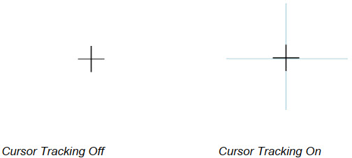
To control wall distance indicators
The wall distance indicators display dimension lines from the cursor to the nearest walls when a tool is active.
1 Choose Home Design Studio > Preferences. The Preferences dialog appears.
2 Click the Editing tab and, under Display Options, select the “Show wall distance indicators” checkbox to enable the dimensions. To disable dimensions, deselect the checkbox.
3 Click Save.
To control the room label display
Room dimensions are available on the Properties pane when a room is selected in the design window.
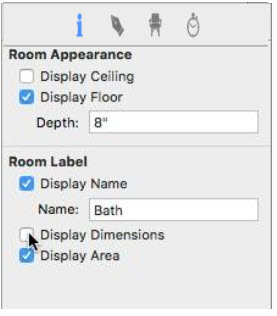
Display Name checkbox controls if the name label appears in the design window. When selected, the text in the Name field appears in the design window. When deselected, the name does not appear. You can edit the text in the field to update the name; be sure to press the Return key to accept changes.
Display Dimensions checkbox controls if the width and height measurements appear in the room label. When selected, the dimensions appear; when deselected they are hidden.
Display Area checkbox controls are the room area that appears in the room label. When selected, the area appears; when deselected it is hidden. Display Ceiling
Display Ceiling checkbox control enables or disables Ceiling Display
Display Floor checkbox control enables or disables Floor Display
1 In 2D Plan view, click the center of the room you want to edit. The room is highlighted in yellow.
2 Click the Properties tab on the right sidebar and, under Room Label, select the label(s) you want to show. Deselect the label(s) you want to hide.
(optional) Edit the Room Name text.
Dimension Wall Spacing
This tool quickly places a dimension between two walls. The dimension must start along a wall, but does not have to end at another wall. When you release, the dimension automatically extends to the nearest wall surface or center, depending on what you specify when the tool is active.
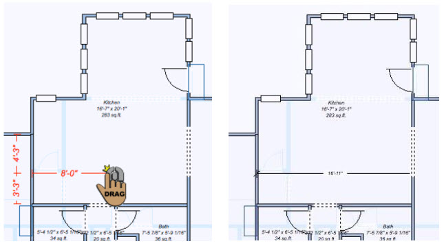
To place a wall-spacing dimension
1 Choose the Wall Spacing  button from the Annotation Tools group in the left sidebar.
2 On the Properties pane, choose to measure From centers or From surfaces.
3 Use the Drag-to-Size drawing method to drag the dimension in the direction of the wall you want to measure to and release to place the measurement.
Zero-Offset Dimension
This creates dimensions from any point, surface, or object, even at angles. In the image below, we’re measuring the distance from the glider to the fireplace.
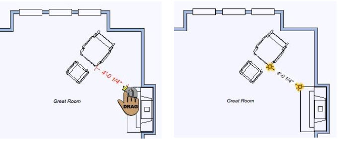
To place a zero-offset dimension
1 Choose the Zero-offset Dimension  button from the Annotation Tools group in the left sidebar.
2 Use the Drag-to-Size drawing method to measure between objects.
Offset Dimension
Offset dimensions are placed with the Offset Dimension Tool. This determines the horizontal or vertical distance between two points.
To place an offset dimension
1 Choose the Offset button  from the Annotation Tools group in the left sidebar.
2 Use the Drag-to-Size drawing method to drag the dimension from the start point of the measurement to the end point of the measurement.
3 Move the pointer in the direction you want the offset dimension to be placed and click to place the dimension.
Length Dimension
This allows you to measure the distance of a single segment by selecting the two end points, the dimension is positioned offset from the segment.
To place a length dimension
1 Choose the Length button  from the Annotation Tools group in the left sidebar.
2 Use the Drag-to-Size drawing method to drag the dimension from the start point of the measurement to the endpoint of the measurement.
3 Move the mouse in the direction you want the offset dimension to be placed and click to place the dimension.
Diameter Dimension
This allows you to measure the diameter of a circle by dragging along the circle’s perimeter, automatically detects the opposite edge and displays the dimension in the middle of the circle.
Note: This dimension applies to circles only; you cannot measure the diameter of an oval.
To place a diameter dimension
1 Choose the Diameter button  from the Annotation Tools group in the left sidebar.
2 Use the Drag-to-Size drawing method to drag along the edge of the circle. The dimension automatically snaps to the opposite edge of the circle.
3 Release to set the dimension.
Leader Dimension
This allows you to annotate your workspace by positioning a single arrow and leader line between two objects, for example, when associating text with a 2D object. You can also automatically add a room’s area and name by pointing into an enclosed room. When you place a leader dimension on a component or object, the description is automatically detected for the annotation. You can edit this as needed. Note: To change the leader type, see “Leader Dimension Properties”.
Once placed, you can edit the label text, including font properties and alignment, as well as change the leader type and arrowhead style. For more information, see “Leader Dimension Properties”.
To place a leader dimension
1 Choose the Leader button  from the Annotation Tools group in the left sidebar.
2 Position the crosshair in the design window where you want the arrow to appear and use the Drag-to-Size drawing method to set the position for the first segment of the dimension.
3 Release the mouse button and drag in the direction you want the second segment to be placed.
4 Click to set the endpoint and place the dimension.
Leader Dimension Properties
Leader dimensions can be customized by editing their text and alignment. You can also choose between a text label or a marker label, and customize the arrowhead style. To edit leader dimension properties, use the Selection Tool to select the dimension in the design window. Its properties are displayed on the Properties tab Edit Leader Text button opens a dialog with the leader text where you can edit the text and font style. For more information, see “Edit Text and Text Properties”, Alignment options allow you to set the text justification for Left, Center, or Right,
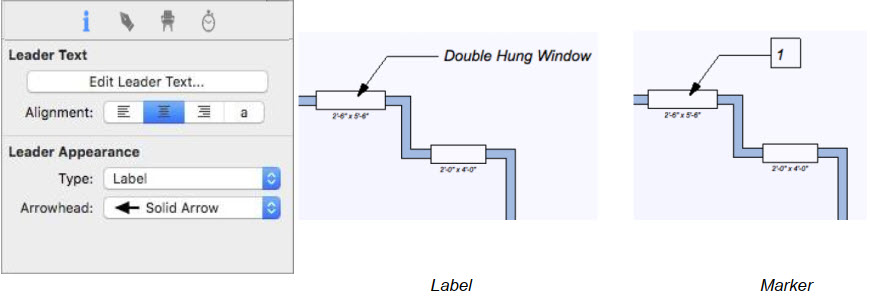
Marker displays an incremental number, with the leader text that is visible when you hover over It with your cursor. This saves space when there is a lot of text to be displayed.
Note: A list of leader markers can be printed. For more information, see “Printing Floor Plans”. The label displays the leader text in the design window.
Arrowhead specifies the arrowhead style for the selected leader dimension.
Dimension and Font Default Settings
There are a number of ways you can control and configure the dimensions and fonts that are displayed in your design. These are the default settings, so changes to the settings are applied to subsequent text or dimensions that are added to your design.
To access dimensioning and font properties
■ Click 2D > Dimension Properties.
Automatic Dimensions Display
The Automatic Dimensions control the display of dimensions in your drawing. You can enable or disable different combinations of dimensions depending on your needs. You can also quickly enable or disable automatic dimensions from the Properties tab.
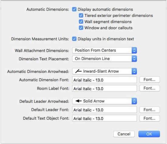
■ Display Automatic Dimension checkbox controls the display of the available dimensions. When selected, dimensions are visible and you can control the display of the available dimensions; when deselected all dimensions are disabled.
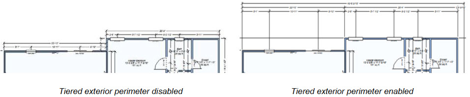
■ Tiered exterior perimeter dimensions checkbox controls the display of wall dimensions that include more than one wall segment. When enabled, both the exterior wall segment dimensions and the total wall measurement are displayed. When disabled, only the individual wall segment dimensions are displayed.
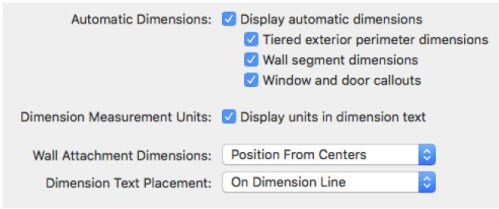
■ Wall segment dimensions control the display of dimensions along with wall segments. To control dimensions on individual walls, see “Wall Properties”.
■ Window and door callouts control the display of dimensions for windows and doors in the design. Select the checkbox to enable; deselect to disable.
(alternatively) You can also control callouts display by selecting or deselecting the Display callouts checkbox on the Properties pane while nothing is selected in the design window or click 2D > Show/
Hide Window and Door Callouts.
■ Dimension Measurement Unit controls the display of the measurement units for dimensions. For example, if the measurement units use English Units, the feet and inch symbols appear when this option is enabled.
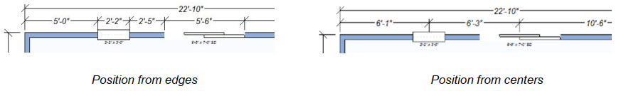
■ Wall Attachment Dimensions pop-up menu allows you to choose the position of wall attachment dimensions.
■ Position from edges measures the distance between each edge of the attachment (its width) and the distance from each edge to the nearest wall.
■ Position from centers measures the distance from the center of the attachment to the nearest wall on either side.
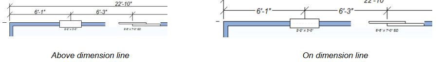
■ Dimension Text Placement pop-up menu specifies how you want dimension text positioned.
■ Above dimension line positions dimension text above the dimension line.
■ On dimension line positions dimensions text along the dimension line.
Automatic Dimension Styles
The Automatic Dimension Styles settings control the look and feel of the automatic dimensions in your drawing. When automatic dimensions are enabled, these arrowhead and font settings are applied.
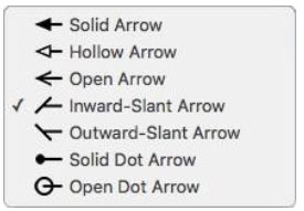
■ Automatic Dimension Arrowhead pop-up menu provides access to the available endpoint styles.
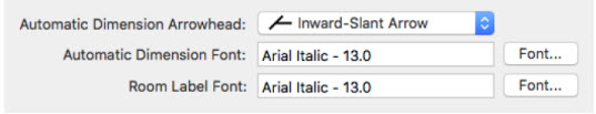
■ Automatic Dimension Font button opens the Font dialog box. These settings control the font used for automatic dimensions. For more details on font settings, see “Edit Text and Text Properties”.
■ Room Label Font button opens the Font dialog box. These settings control the font used for room labels when the Label Name is enabled. For more details on font settings, see “Edit Text and Text Properties”.
Default Font and Leader Style
The Default Font and Leader Dimension Styles settings control the look and feel of the leader dimensions and text you add to your drawing.
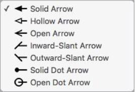
■ Default Leader Arrowhead pop-up menu provides access to the available endpoint styles for leader dimensions. The default is applied to all leader dimensions.
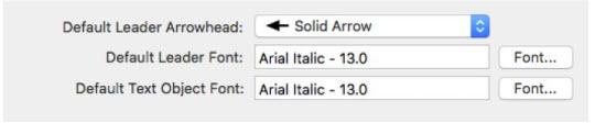
■ Default Leader Font button opens the Font dialog box. These settings control the font used for text associated with leader dimensions. For more details on font settings, see “Edit Text and Text Properties”.
■ Default Text Object Font button opens the Font dialog box. These settings control the font used for text added using the text tools. For more details on font settings, see “Edit Text and Text Properties”.
Design Colors
When creating a design, the organization is not only important but extremely helpful. To enhance organization and efficiency, many of the features in Punch! are color-coded so they are easily noticeable in the design window. For example, each of the floor plans appears in a different color in the design window. The Foundation plan appears in red, while the Floor plan is black, and Electrical components appear in orange. So, at a glance, you can distinguish one-floor plan from another. Each of these colors can be customized.
Along with the plans, the plan background, inactive floors, interior fill, topography lines, ClearView, Wireframe Background, and grid colors can be customized.
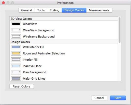
To change a design color
1 Choose Home Design Studio > Preferences. The Preferences dialog appears.
2 Click the Design Colors tab and choose the thumbnail for the color you want to change. The Colors window appears.
For example, if you want to change the color that Plumbing components appear in the design window, click the color next to Plumbing Plan. The current color appears in the Colors window, as seen below. There are five panes of coloring options.
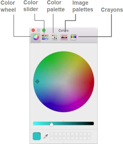
3 Select the pane you want to use and choose a color, then close the window.
4 Click Save to save your preferences.
To reset all colors
1 Choose Home Design Studio > Preferences. The Preferences dialog appears.
2 Click the Design Colors tab, then click the Reset Colors button. Each feature’s color is reset to its default color.
3 Click Save to save your preferences.
Draw Style Tab
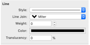
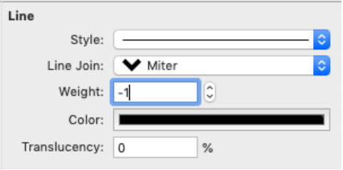
Draw style tab contains different formatting tools for lines, shapes, and texts, allowing the change of thickness, the addition of patterns and colors as well as the adjustment of the transparency.
Font and Color
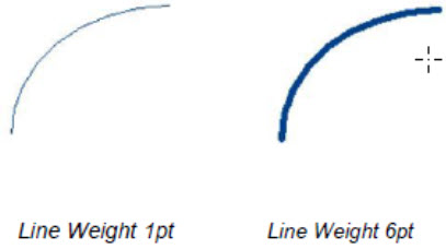
You can choose a predefined line weight from the weight drop-down menu or specify a value up to 20pt. To edit the line weight, you must select the line or shape first.
To change the line weight
-
Click the Selection Tool and then select the element you want to edit.
-
On the Draw Style Tab, Click the weigh drop-down menu and choose one of the sizes.
To specify a custom line weight
-
Click the Selection Tool and then select the element you want to edit.
-
On the Draw Style Tab, click the Weigh drop-down menu and choose another from the menu. The Line Weight dialog box is displayed.
-
Type a value in the Points text box or click the arrows to edit incrementally and then click OK.
Line Style
You can choose a predefined line style from the Line Style drop-down menu. To edit the line style, you must select the line or shape first.
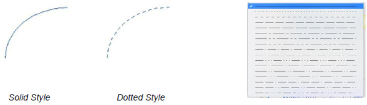
To change the line style
1. Click the Selection Tool and then select the element you want to edit.
2. On the Draw Style Tab, click the Line Style drop-down menu and choose one of the styles from the menu
3 On the Draw Style Tab, select the desired Line Style, Color and Translucency and click to apply.
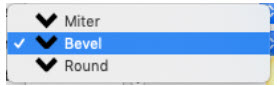
Line join
You can choose a predefined line cap styles (miter, bevel, rounded) from the Line Join drop-down menu. To edit the line cap style, you must select the line or shape first.
To change the line cap style
1. Click the Selection Tool and then click to select the element you want to edit.
2. On the Draw Style Tab, click the Line-Join drop-down menu and choose one of the styles from the drop-down menu.
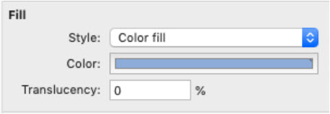
Fill
You can change an element’s fill using a solid color (Color Fill), or transparent (No fill). To edit an element’s fill properties, you must select the element first.
To change the shape fill
1. Click the Selection Tool and then select the element you want to edit.
2. On the Draw Style Tab, select the desired Fill Style, Color and Translucency and click to apply.
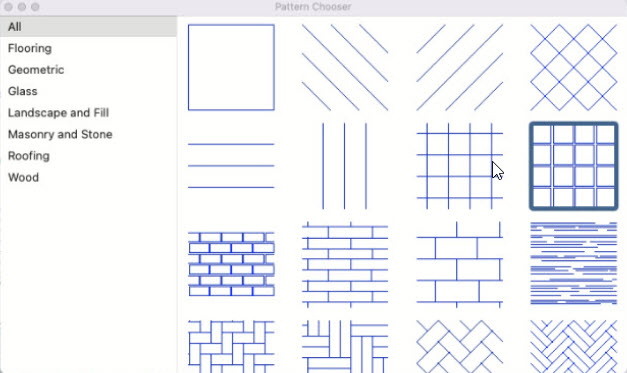
Fill pattern
You can change a shape’s fill pattern to be transparent, a solid color, or a patterned fill. You can rotate the pattern as well. Fill patterns added along with support for expandable fill pattern library through downloadable content
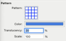
The fills, from left to right, include:
-
Transparent
-
Filled
3. Scale
- Patterns
To change the shape fill
1. Click the “Select/ Move Objects Tools” and then click to select the element you want to edit.
2. On the Draw Style Tab, click on the Pattern drop-down menu and choose the available options.
3. Color and Transparency can be changed by using the Color and Translucency scale respectively.
Text
You can change text color and transparency from this tool. To edit a text, you must select the text first.
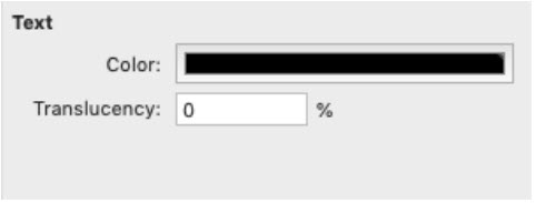
To change the text
1. Click the Selection Tool and then select the text you want to edit.
2. On the Draw Style Tab, select the desired Color and Translucency and click to apply.