HVAC Plan Tab
Correctly adding HVAC ducts and units is an important part of the home design process. Punch! Home Design Software makes it easy to flawlessly design your HVAC system, making sure all rooms receive adequate ventilation. Once you place HVAC, with a few mouse clicks, it’s easy to adjust or move components. You can even move components by a specific distance, based on Cartesian or Polar coordinates, or rotate items, as needed.
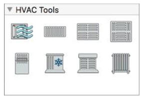
The HVAC Tools are available in the left sidebar. For information on accessing the left sidebar, and controlling the display of the tools that appear, see “Left Sidebar”

Placing Air Ducts
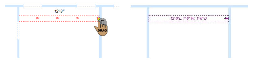
Punch! Home Design Software features several sized air ducts to ensure the perfect HVAC plan. To place air ducts simply drag to define the length and angle of the component. Air ducts are drawn horizontally and vertically, just as standard HVAC ducts are actually placed in a new home. You can move air ducts by dragging a specific distance or rotating them to fit your home design. If you don’t find the perfectly-sized air duct for your home plan, you can edit the width and depth on the Properties pane before or after you draw the air duct. Air ducts are visible in the 2D view only.
To place an air duct
1 Choose the Air Duct  button from the HVAC Tools group.
2 Use the Drag-to-Size drawing method to set the angle and length for the air duct.
Air Duct Properties
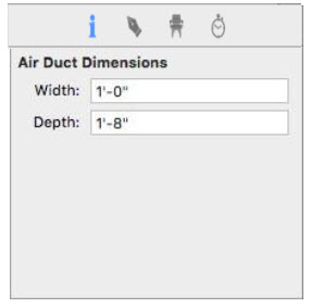
Air ducts are defined by their width and depth. You can edit the properties before you draw or after the component has been added to your design by selecting it and clicking the Properties tab in the right sidebar.
Note: When editing values, always press Return to accept new values in a field.
Width defines the distance from one side of the air duct to the other (length is the distance from the endpoint to endpoint).
Depth defines the distance from the bottom of the air duct to the top (this dimension is not represented in 2D).
Placing Vents and Registers
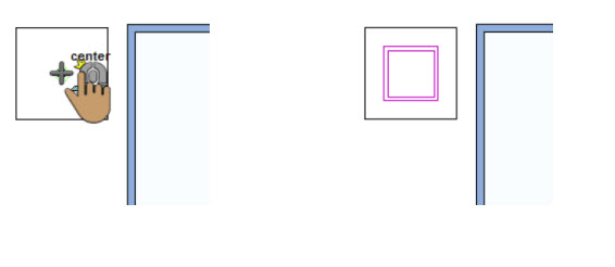
Placing vents and registers involves one mouse click. Once you’ve placed vents, you can move them by dragging or defining specific coordinates. You can even rotate vents at custom angles to fit your design. Punch! Home Design Software provides several vents to choose from, including floor, ceiling, and wall vents. You can choose the register style on the Properties pane in the right sidebar before or after your place it in your design.
To following options are available in the HVAC Tools group:
■ Floor Registers
■ Wall Register/Return
■ Ceiling Register/Return
Floor Registers
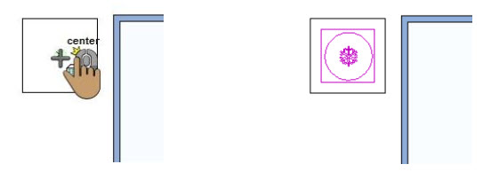
Floor registers are placed at the auto-floor elevation if the auto-floor is enabled. Otherwise, the register is placed at the base elevation for the current floor. If you’ve created a floor manually (using the Floor Tool) you should adjust the register elevation to match that of the floor. When the tool is active you can choose the style you want on the Properties pane. You can also change the style after the register has been placed by selecting the register in your drawing and choosing a different style.
To place a floor register
1 Choose the Floor Register  button from the HVAC Tools group.
2 Use the Click Once to Place drawing method to place the register in your design.
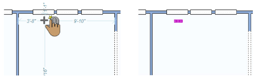
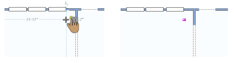
Wall Register/Return
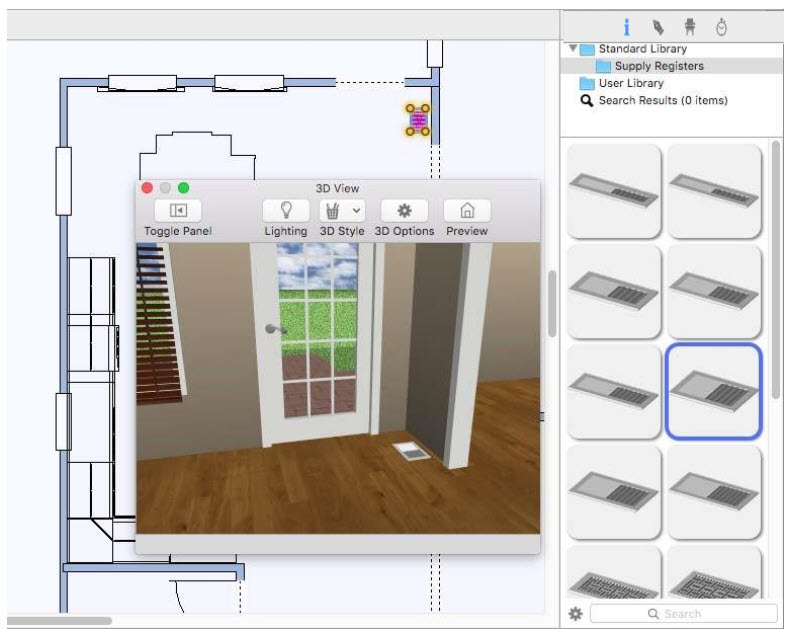
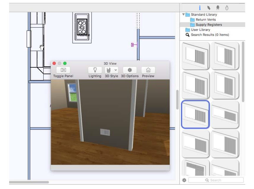
Wall registers and vents are placed on a wall at a default elevation. As you drag along a wall, the dimension lines indicate the distance from the center of the register/vent to the nearest wall end or wall attachment. When the tool is active you can choose the style you want on the Properties pane. You can also change the style after the register/vent has been placed by selecting the component in your drawing and choosing a different style. There are two libraries available: Return Vents and Supply Registers. When a library is selected, its contents are displayed in the Preview Bar.
To place a wall register or return
1 Choose Wall Register/Return  button from the HVAC Tools group.
2 Use the Drag Along Wall drawing method to position the register/return on the side of a wall where you want it and release it to place.
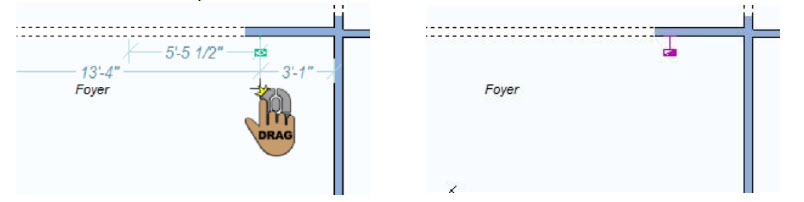
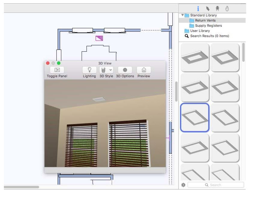
Ceiling Register/Return
Ceiling registers are placed at the auto ceiling elevation. If you’ve created a ceiling manually (using the Floor Tool) you may need to adjust the register/vent elevation to match that of the ceiling. When the tool is active you can choose the style you want on the Properties pane. You can also change the style after the register/vent has been placed by selecting the component in your drawing and choosing a different style. There are two libraries available: Return Vents and Supply Registers. When a library is selected, its contents are displayed in the Preview bar.
To place a ceiling register or return
1 Choose Ceiling Register/Return  button from the HVAC Tools group.
2 Use the Click Once to Place drawing method to place the register/return in your design.
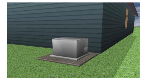
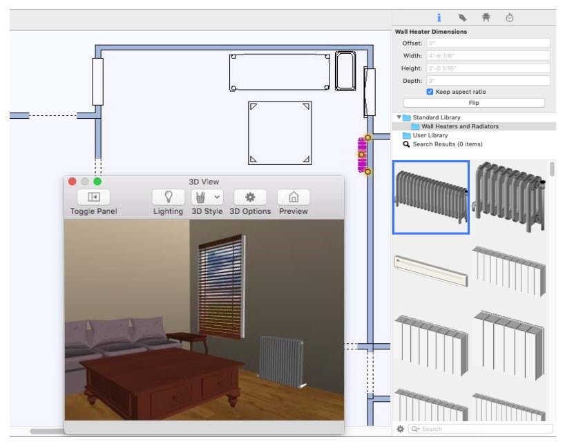
Adding Heating, Air Conditioning Units, and Pumps
Adding heating and air conditioning units only involves one mouse click. Once placed, you can move units by specific distances, drag to move them, and even rotate them to fit your home design.
To place a furnace
1 Choose the Furnace  button from the HVAC Tool group.
2 Use the Click Once to Place drawing method to place the furnace in your design.
To place an air conditioner
1 Choose the Air Conditioner  button from the HVAC Tool group.
2 Use the Click Once to Place drawing method to place the air conditioner in your design.
To place a heat pump
1 Choose the Heat Pump  button from the HVAC Tool group.
2 Use the Click Once to Place drawing method to place the heat pump in your design.
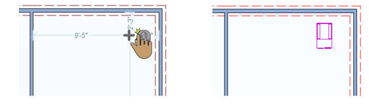
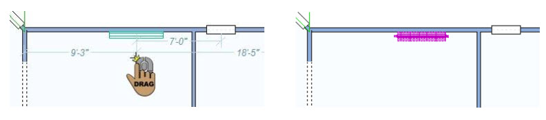
Placing Baseboard Heaters
As you place baseboard heaters and radiators in your home plan, the component is automatically “tracked” to the wall segment, making accurate placement simple. Dimension lines automatically appear, as you drag and after it is placed, making it easy to place heaters a specific distance from a neighboring HVAC component or wall segment. When the tool is active you can choose the style you want from the Properties pane in the right sidebar. You can also change the style after the heater or radiator has been placed by selecting the component in your drawing and choosing a different style.
To place a heater
1 Choose the Baseboard Heater  button from the HVAC Tool group.
2 Use the Drag Along Wall drawing method to position the heater on the side of a wall where you want it and release it to place.
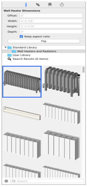
Heater and Radiator Properties
Once placed, heaters and radiators are defined by their length, width, and how far they are offset from the wall. You can edit the properties after the component has been added to your design by selecting it and clicking the Properties tab in the right sidebar.
Note: When editing values, be sure to press Return to accept new values in a text field.
Width defines the span of the heater or radiator along the wall.
Depth defines the distance from the back of the heater or radiator to the front.
Offset defines the distance between the wall and the heater or radiator. To position it right up against the wall, set the value to 0.
Standard Library includes the Wall Heaters and Radiators content library. You can choose the style in the Preview Bar before or after you place the heater.
Flip button allows you to flip the side where the hardware is positioned. For more information on working with library content, including the User Library, see “Organizing Library Content”.
Note: You can flip the side where the hardware is positioned by right-clicking the heater in the design window and choosing Flip Component.