Control 3D Options
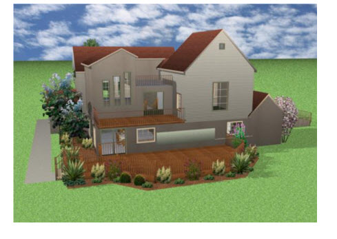
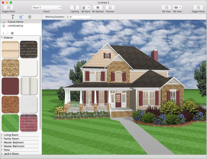
Punch! Home Design Software lets you view your design in photo-realistic 3D. You can select exterior and interior wall color, add realistic roof materials and select from a variety of wood textures to make your design completely unique. In the 3D View window, you can view your design from a variety of angles. Using Decorator Palettes, you can easily make changes to your decorating theme. This makes it easy to experiment with a variety of color schemes, both inside and outside your design, before picking up a paintbrush! With the powerful ClearView feature, you can literally see through the walls and view electrical, plumbing, and so on.
Home Design integrates the exclusive, patented RealModel® technology, making it easy to construct an actual scale model of any home you draw. Once you have completed your home design, details are automatically transferred to RealModel. Instructions on building your home model are printed, with numbered sections and floor plan templates that make assembly simple. This hands-on model shows you how to improve your design and save on construction costs before you break ground. This is the perfect tool for presenting your ideas to your builder or architect.

Moving Around in 3D
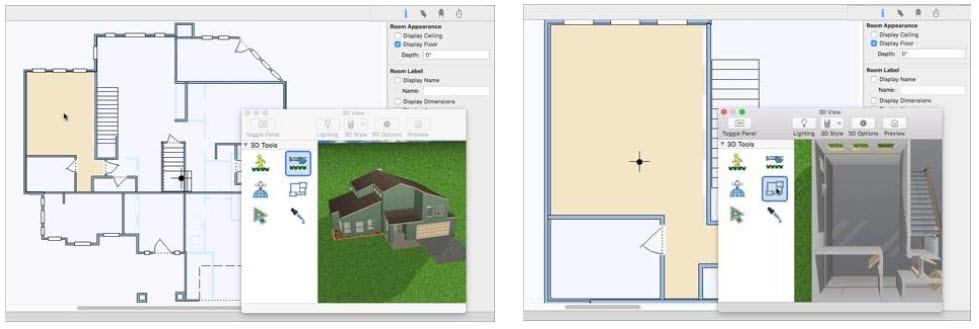
Home Design Studio Complete provides two interactive 3D viewing options, the 3D Walkthrough, and Fly-Around views, as well as an overhead aerial view and a room view, to focus on selected rooms in the design. Using interactive viewing, you can vary the viewing level by adjusting the altitude and height. Viewing speed and camera angle can also be adjusted to provide the best viewing capabilities available. The navigations tools are accessible from the 3D Tools group in the left sidebar when a 3D view is open.
Walkthrough Mode
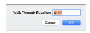
Using 3D Walkthrough mode, you can navigate your design as if you were walking through it. You can navigate the exterior, walkthrough rooms, and even adjust the viewing elevation to change floors. The default walkthrough elevation is 5'-0". There are two ways to adjust the walkthrough elevation, which are described below.
To view your design using Walkthrough
1 Open a 3D View window and choose the Walkthrough  button from the 3D Tools group.
(alternatively) Choose 3D > 3D Navigation Method > Walkthrough.
2 In the 3D View, drag to navigate around your design; drag up to move inward, down to move outward.
To set your 3D viewpoint in 2D
You can adjust the walkthrough view in the 2D design window using the Viewpoint  icon. You may need to zoom out in the 2D view to find the Viewpoint icon initially.
1 Open the 3D Window View and choose the Walkthrough  button so you can see both 2D and 3D.
2 In the 2D view, drag the Viewpoint icon center point to a new location in the design window to update the 3D view. Drag the arrow around the center point to rotate the view.
To change your Walkthrough elevation
■ In the 3D View, hold down the Control key while pressing the mouse button and drag up or down to raise or lower the elevation.
(alternatively) Choose 3D > 3D Navigation Method > Walkthrough and enter a new Walk Through Elevation then click OK.
(alternatively) Using two fingers on the trackpad, swipe up or down.
Fly Around Mode
Using Fly Around mode, you can navigate your design as if you were flying around it. This gives you a bird’s eye view of your exterior. You can even adjust the viewing elevation to get a closer look at some areas or see the bigger picture.
To view your design using Fly-Around
1 Open a 3D View window and choose the Fly Around  button from the 3D Tools group.
(alternatively) Choose 3D > 3D Navigation Method > Fly Around.
2 In the 3D View, drag to navigate around your design; dragging up and down changes your viewing angle, while dragging side-to-side navigates around the designated center of reference.
To specify a center of reference in Fly-Around mode
You can adjust the fly-around reference point in the 2D design window using the Center of Reference icon. You may need to zoom out in the 2D view to find the Center of Reference icon initially.
1 Open the 3D Window View and choose the Fly Around  button so you can see both 2D and 3D.
2 In the 2D view, drag the Center of Reference  icon to specify the point that the view revolves around.
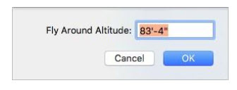
To change Fly-Around altitude
■ In the 3D View, hold down the Control key while pressing the mouse button and drag up or down to raise or lower the altitude.
(alternatively) Choose 3D > 3D Navigation Method > Fly-Around Altitude and enter a new FlyAround Altitude then click OK.
(alternatively) Press down with two fingers on the trackpad, and swipe up or down.
Aerial View Mode
This is a top-down view of your design. Use the Cutaway Slider to remove layers so you can see into your design. While viewing in aerial mode, you can pan the view and adjust your viewing altitude.
To see an aerial or bird’s eye view of your design
1 Open a 3D View window and choose the Aerial View  button from the 3D Tools group.
(alternatively) Choose 3D > 3D Navigation Method > Aerial View.
2 Drag to pan around the 3D View, or hold down the left mouse button and press the arrow keys to move the aerial view incrementally. To rotate around the designated center of reference, right-click and drag.
To specify a center of reference in Aerial mode
You can adjust the aerial reference point in the 2D design window using the Center of Reference icon. You may need to zoom out in the 2D view to find the Center of Reference icon initially.
1 Open the 3D Window View and choose the Aerial View  button so you can see both 2D and 3D.
2 In the 2D view, drag the Center of Reference  icon to specify the point of view.
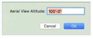
To change your aerial view altitude
■ In the 3D View, hold down the Control key while pressing the mouse button and drag up or down to raise or lower the altitude.
(alternatively) Choose 3D > 3D Navigation Method > Aerial View Altitude and enter the Aerial View Altitude then click OK.
(alternatively) Using two fingers on the trackpad, swipe up or down.
Room View Mode
Using Room View, you can choose a room or space in 2D that you want to view in 3D. Once the view appears you can navigate and adjust the viewing altitude.
To see a room view of your design
1 Open a 3D View window so you can see the 2D and 3D views.
2 In the design window, click to select the room(s) you want to view. You can use the Select Objects tool in the 2D or 3D view.
Note: Press and hold Shift while clicking to select multiple rooms in 2D.
3 Click the Room View  button from the 3D Tools group. The 2D and 3D views are updated to focus on the selected room(s).
(alternatively) Choose 3D > 3D Navigation Method > Room View.
You can navigate the 3D view using your mouse
■ Drag to pan.
■ Right-click and drag to rotate.
■ Use the wheel on your mouse to adjust your viewing elevation.
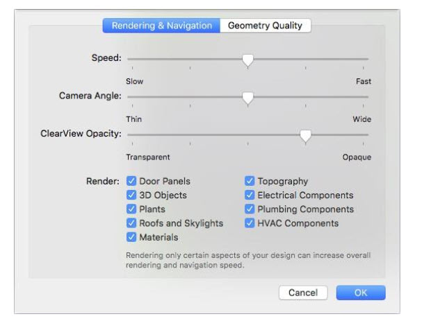
Setting Navigation Options
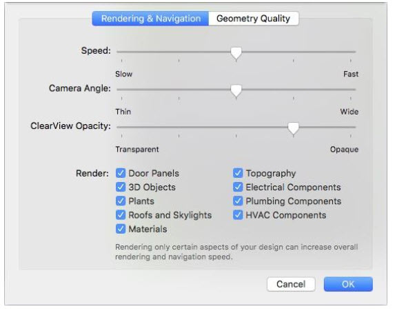
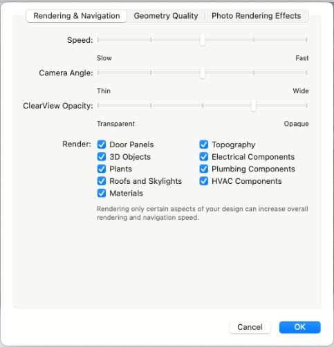
You can control the speed and the camera viewing angle as you navigate in 3D. These settings are available from the 3D view window or from the 3D menu. The Speed slider controls the 3D navigation speed; drag the slider to decrease or increase the speed. The faster the viewing speed, the lower the quality of the rendered 3D image. The Camera Angle slider controls how thin or wide the camera angle appears when viewing in 3D.
To adjust navigation options
1 Open a 3D view and click the 3D Options  button on the toolbar.
(alternatively) Choose 3D > Rendering Options.
2 Click the Rendering & Navigation tab, then adjust the Speed and Camera Angle settings, and then click OK.
Accessing the 3D Rendering Styles
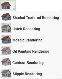
With Home Design Studio Complete’s five 3D rendering options you can view your design in a variety of ways. You can access the rendering styles from the 3D view toolbar or the 3D menu.
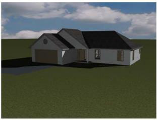
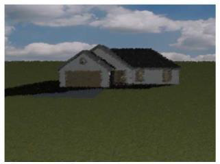
Shaded texture  shows all of the paint, material, objects, and plants.
ClearView lets you see potential conflicts hidden by walls, for example, between utilities, and so on.
The ClearView Opacity is controlled by the Rendering & Navigation options, which you can access from the 3D view window toolbar or from the 3D menu. Drag the slider to control how transparent or opaque the view appears.
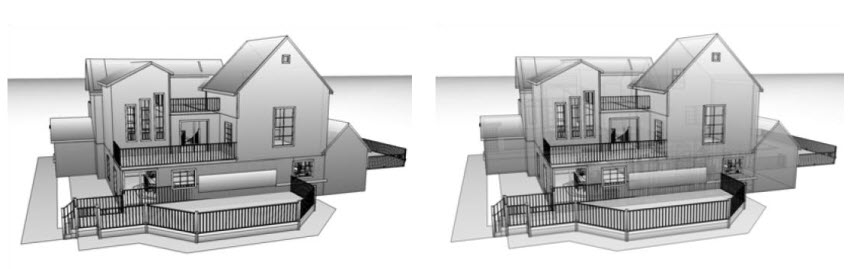
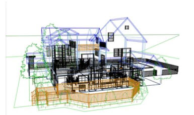
Colored Wireframe mode displays your design on a white background. Each feature of your floor plan will be rendered in the color of the plan tab where it is drawn. For example, walls will be displayed in the color you have defined for the Floor Plan.
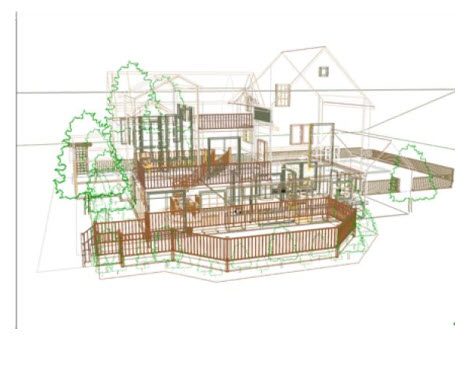
Textured Wireframe  mode also displays your design on a white background. But, each feature of your floor plan will be rendered in the color of the material you have applied to it.
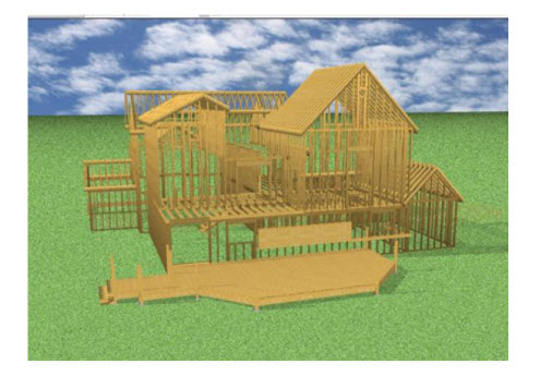
Framing  mode displays your design to show the studs, rafters, and other framing features. Wall attachments such as plumbing and electrical components are not visible while in framing mode.
 Accessing the Photo-Realistic Rendering Styles
There are six Photo-realistic rendering styles available. To access the Photo-Realistic rendering styles, be sure Photo-Realistic Rendering mode is activated.

Hatch the hatch style produces an effect similar to a shaded pencil drawing. The image is made up of a series of pencil “strokes” all in a similar orientation. All of the strokes are to provide shading - no lines are drawn.
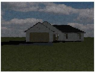
 Mosaic the mosaic style has the effect of rendering as though the design were constructed as a mosaic of small colored tiles.
 Oil Painting the oil painting style creates an effect reminiscent of some impressionist painters, with individual blobs of paint of a single color applied across the canvas (which could be brush or palette- knife strokes). The overall image only resolves itself if you view from far enough away.
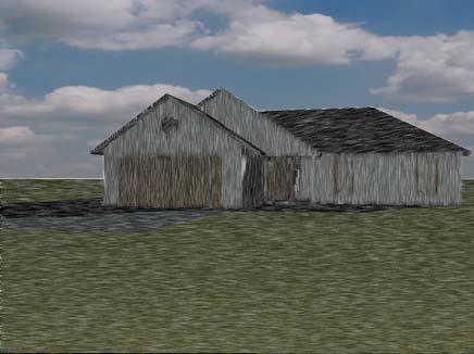
 Contour creates the effect where strokes and swirls of color reflect and represent the orientation of the underlying geometry. The effect may also resemble using colored pencils to shade the image (with the direction of the pencil strokes matching the underlying geometry at all times).

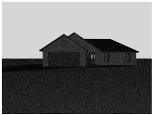
Stipple the stipple style renders as a series of irregular dots, or stipples. The effect is similar to how photographs are reproduced in newsprint, only more pronounced.
To view a 3D photo-realistic rendering style
1. Click 3D menu > Rendering Mode > Photo-Realistic Rendering and then open a 3D View window.
2. In the 3D View window, click the Render Style button, then choose the rendering style you want.
(alternatively) Click 3D menu > Photo-Realistic Rendering > Rendering Style and choose the style you want.
Adjusting Photo-Realistic Rendering Quality
The photo-realistic styles that are available can be applied using one of the two render options: preview or final. Rendering in photo-realistic quality also applies any effects you may have selected for your design.
To render a Photo-Realistic preview 
1 Open a 3D View window and click the Render Preview button. This option renders a lower-quality, faster preview of the design.
(alternatively) Click 3D menu > Photo-Realistic Rendering > Render Preview.
To render in Photo-Realistic final quality
1. Open a 3D View window and then click 3D menu > Photo-Realistic Rendering > Render Final.
Setting Rendering Options
With Punch! Home Design Software you can customize the render quality of many of the customized features you use. By setting these features to lower render quality, you can speed up the rendering time.
To set the render options
- Open a 3D View window and click the Navigation and Rendering Options button on the 3D View window. The Design Options dialog box opens to the Navigation & Render Quality settings
(alternatively) Click 3D menu > 3D Rendering > Render Options.
- Drag the sliders to set the rendering quality for each feature you want to change and then click OK. Note: The lower the render quality is set, the faster the 3D View will render your design.
Setting Photo-Realistic Rendering Effects
With Punch! Home Design Software you can apply outdoor effects to simulate fog and snow. These options are available from the Design Options window and are visible after rendering your 3D photo-realistic view
To add a fog effect to the exterior view
1. Open a 3D View window and click Design menu > Options. The Design Options dialog box is displayed.
2. Under 3D Preferences, click Photo Rendering Effects. The options are displayed in the right pane.
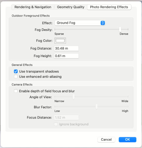
3. Click the Effect drop-down menu and choose Fog or Ground Fog. The fog effect options are displayed.
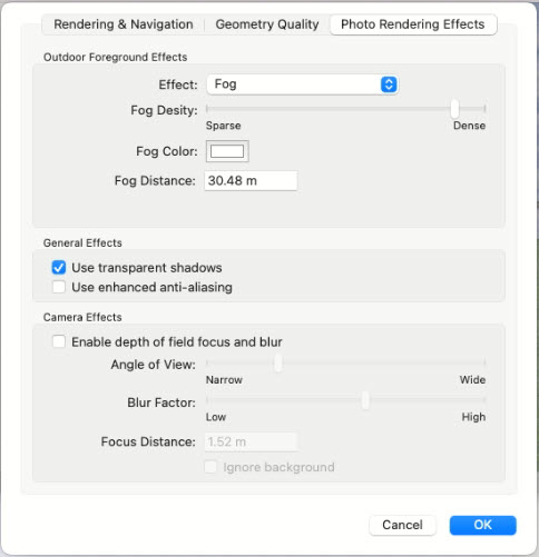
- Fog Density slider adjusts how sparse or dense the fog is displayed.
- Fog Color preview opens the Color window and allows you to select a color for the fog.
- Fog Distance controls how far the fog extends.
- Fog Height control how high from the ground the fog extends (only applies to Ground Fog).
- Select or deselect Use transparent shadows to enable or disable this option.
- Select to deselect Use enhanced anti- aliasing to enable or disable this option.
4. Click OK. To see the effect, render the drawing.
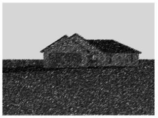
To add a snow effect to the exterior view
1. Open a 3D View window and click Design menu > Options. The Design Options dialog box is displayed.
2. Under 3D Preferences, click Photo Rendering Effects. The options are displayed in the right pane.
3. Click the Effect drop-down menu and choose Snow. The snow effect options are displayed.
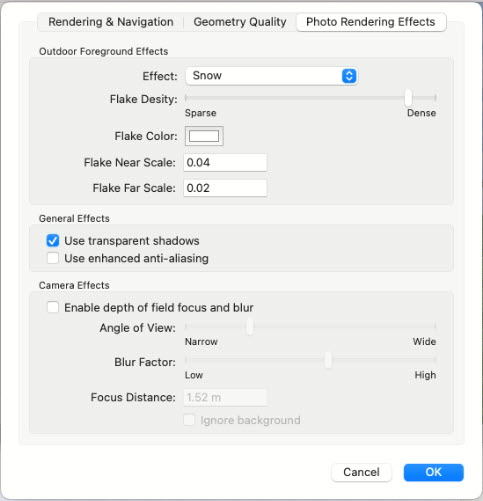
- Flake Density slider to adjust how sparse or dense the snowflakes are displayed.
- Flake Color preview opens the Color window and allows you to select a color for the flakes.
- Flake Near Scale determines the size of the closer flakes in the view.
- Flake Far Scale to determine the size of the further flakes in the view.
- Select or deselect Use transparent shadows to enable or disable this option.
- Select or deselect Use enhanced anti-aliasing to enable or disable this option.
4. Click OK. To see the effect, render the drawing.
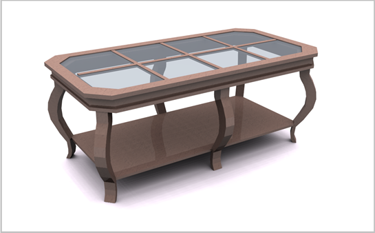
Depth of Field Focus
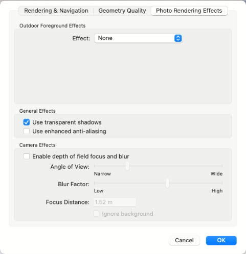
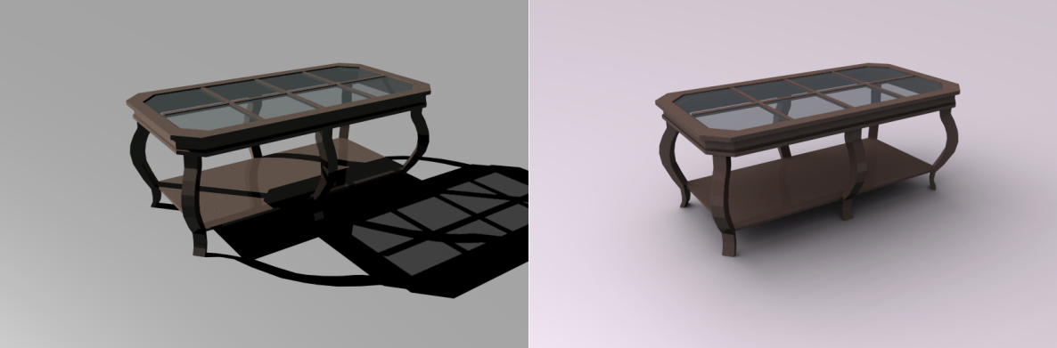
When Photo-Realistic rendering is enabled, you can adjust the depth of field focus settings to control the focus distance and how the non-focal space is displayed in your 3D view. The depth of field settings includes a focus distance, viewing angle width, and the amount of blur. The Focus Distance is the distance from the viewpoint to the point of focus in your drawing. You can measure this distance using the Virtual Ruler ) or one of the Dimensioning tools The Angle of View setting determines how narrow or wide the blur factor appears at the specified focus distance. The wider the setting, the more blur affects the scene. The Blur Factor setting controls how blurry the areas outside the focus distance appear.
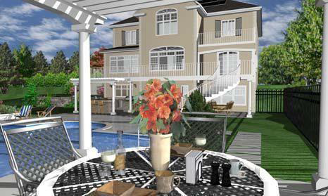
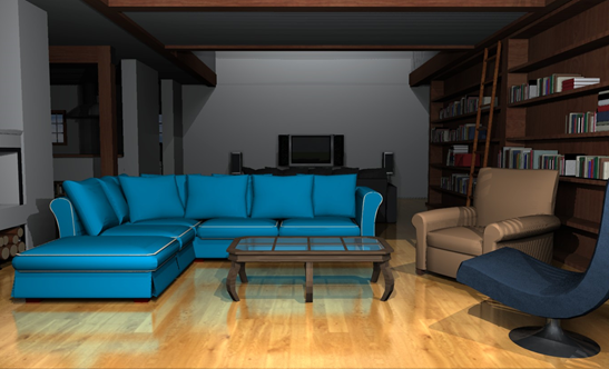
In this example, the Depth of Field is disabled. You can clearly see the foreground objects and the house in the background.
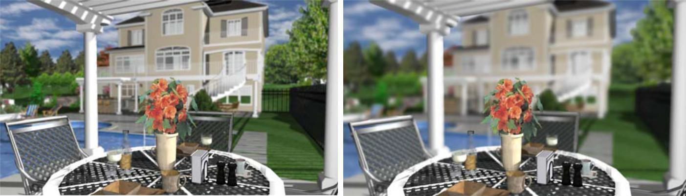
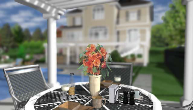
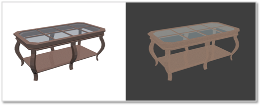
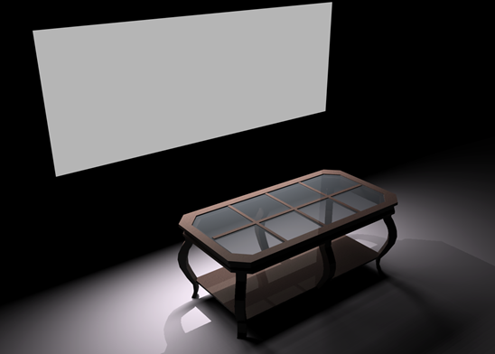
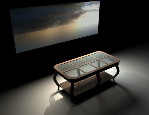
Depth of Field enabled with medium Blur Factor Depth of Field enabled with high Blur Factor
The focus is on the table in the foreground, which is very clear while the background is blurred.
To enable depth of field
1. Click 3D menu > Rendering Mode > Photo-Realistic Rendering and open a 3D View window.
2. Click Design menu > Options. The Design Options dialog box is displayed.
3. Under 3D Preferences, click Photo Rendering Effects. The options are displayed in the right pane.
4. Under the Camera Effects section, select the Enable depth of field focus and blur checkbox. The depth of field settings becomes enabled.
- Angle of View slider controls how narrow or wide the amount of space the blur occupies.
- Blur Factor slider controls the amount of blur outside of the specified focus distance area.
- Focus Distance text box defines the distance from the current viewpoint to the desired focus point.
- Ignore Background checkbox that controls whether the background image is rendered with the design. To include the background when rendering with the depth of field enabled, deselect the Ignore Background checkbox; to exclude, select the checkbox.
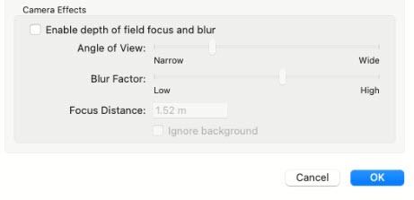
- Click OK.
Rendering 3D Effects
The 3D Effects tab contains reflection and displacement effects, which can be applied to objects and surfaces in 3D.
You can see the effects using 3D Rendering when they are applied to surfaces such as floors, decks, and stairs, also flat surfaces on 3D objects. 3D Effects can also be rendered using the Photo-Realistic Rendering option.
To render 3D effects
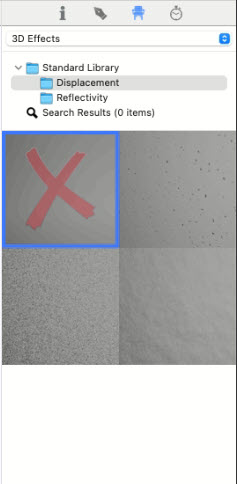
1. Click the Libraries tab and choose 3D Effects from the Libraries drop-down menu. The 3D Effects categories become available.
2. Click the Categories drop-down menu and choose Displacement or Reflectivity. Its contents are displayed in the Preview Bar.
3. Scroll through the options and drag and drop the effect you want onto the surface, in 3D.
4. Render the image to see the effect.
You can see the effects using 3D Rendering when they are applied to surfaces such as floors, decks, and stairs, also flat surfaces on 3D objects. 3D Effects can also be rendered using the Photo-Realistic Rendering option.
To render 3D effects
1. Click the Libraries tab and choose 3D Effects from the Libraries drop-down menu. The 3D Effects categories become available.
2. Click the Categories drop-down menu and choose Displacement or Reflectivity. Its contents are displayed in the Preview Bar.
3. Scroll through the options and drag and drop the effect you want onto the surface, in 3D.
4. Render the image to see the effect.
To remove a 3D effect
1. Click the Libraries tab and choose 3D Effects from the Libraries drop-down menu. The 3D Effects categories become available.
2. Click the Categories drop-down menu and choose Displacement or Reflectivity. Its contents are displayed in the Preview Bar.
3. Drag and drop the first option onto the surface in 3D.
To view a 3D rendering style
1 Open a 3D view window.
2 Click the 3D Style  button on the toolbar and choose the rendering style you want.
(alternatively) Choose 3D > Rendering Style and then choose the rendering style you want.
To adjust ClearVIew Opacity options
1 Open a 3D view and click the 3D Options  button on the toolbar.
(alternatively) Click 3D > Rendering Options.
2 Click the Rendering & Navigation tab, then adjust the ClearView Opacity setting and then click OK.
Adjusting 3D Rendering Quality
Home Design Studio Complete technology includes anti-aliased, photo-realism. With this technology, you can view your plan with incredible detail, whether you are in ClearView, viewing materials, viewing framing, or using another render style.
Render the 3D View
There are a few options for rendering your 3D view. You can quickly render a preview or render a final quality view. You can also control the display of shadows, which is described in “Adding Lighting and Shadows”.
To render a 3D preview
■ Open a 3D View window and click the Preview  button in the 3D View window toolbar.
To render a plan in 3D final quality
■ Open a 3D View window and choose 3D > Render 3D Final Quality.
To set 3D render quality
■ Open a 3D View window and choose 3D > 3D Final Quality and choose one of the options.
Note: You can stop the rendering process at any time by pressing the Esc. key.
■ Low results in a fast rendering speed, but lower quality output.
■ High results in a moderate rendering speed and average quality output.
■ Ultra-High results in a slower rendering speed and a high-quality output.
■ Excellent results in a very slow rendering speed, but very high quality, sharp output.
Rendered Objects in 3D
Render options allow you to see your design without specific features, objects, and so on. With Home Design Studio Complete you have complete control over what parts of your design are visible.
To configure rendered objects
1 Open a 3D view and click the 3D Options button on the toolbar.
(alternatively) Click 3D > Rendering Options.
2 Click the Rendering & Navigation tab, then select the object(s) that you want to show or deselect the object(s) you want to hide in 3D then click OK.
Object Render Quality
You can customize the render quality of many of the customized features you use in your design. By setting these features to lower render quality, you can speed up the rendering time.
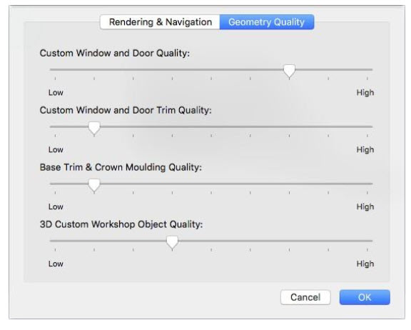
Custom Window and Door Quality slider allow you to increase or decrease the 3D quality of windows and doors.
Custom Windows and Door Trim Quality slider allows you to increase or decrease the 3D quality of window trim and door trim.
Base Trim & Crown Moulding Quality slider allows you to increase or decrease the 3D quality of base trim and crown molding.
3D Custom Workshop Object Quality slider allows you to increase or decrease the 3D quality of 3D Custom Workshop objects.
To access render quality settings
1 Open a 3D view and click the 3D Options  button on the toolbar.
(alternatively) Click 3D > Rendering Options.
2 Click the Geometry Options tab, then drag the slider to set the rendering quality for each feature you want to change, and then click OK.
Adding Lighting and Shadows
With Home Design Studio Complete, you can customize the lighting and shadows. You can virtually see how that big oak tree casts shadows into your living room window.
To adjust lighting settings
1 Open a 3D View window and click the Lighting button in the 3D View toolbar. A dialog appears.
(alternatively) Choose 3D > Lighting Options.
2 Edit the settings as needed and then click Apply and render the design to see the effect.
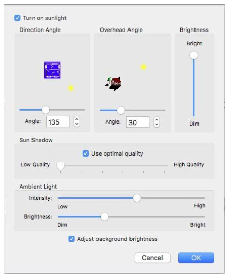
Turn sunlight on checkbox enables all of the sunlight settings in the 3D when selected; the sunlight settings are ignored when deselected.
Direction Angle slider controls the direction from which the sun shines. Drag the slide to position the sun around the plan or use the Angle field or stepper controls to specify the angle you want.
Overhead Angle slider controls the sun’s angle in the sky. Drag the slider to adjust the angle from which the sun shines or use the Angle field or stepper controls to specify the angle you want.
Brightness slider increases or decreases the sun’s brightness. Drag to adjust the brightness as needed.
Sun Shadow settings are disabled when “Use optimal quality” is selected. To edit the settings, deselect the
Use optimal quality checkbox and drag the slider to change the sun’s shadow quality. (A lower shadow quality speeds up rendering times, while a higher quality slows down rendering times.)
Ambient Light is controlled by the Intensity and Brightness settings. Drag the sliders to increase or decrease the ambient light appearance.
Adjust Background Brightness checkbox controls if the background image is affected by the Sunlight or Ambient Light settings. When selected, lighting settings affect the background as well; when deselected the background is not updated when lighting settings are changed.
Note: You can further specify the sun positioning by defining your exact location, as well as the date and time. For more information, see “Customizing the Sun Position”, which begins on page 258.
To render shadows to a 3D view
1 Open a 3D View window, as explained previously.
2 Choose 3D > Render Shadows. Shadows are rendered in the 3D View.
To control shadow quality
1 Open a 3D View window, as explained previously.
2 Choose 3D > Shadow Quality then choose the quality you want from the submenu.
Photo-Realistic Scene Lighting
The Photo-Realistic Rendering mode offers various scene lighting options for controlling the amount of light in a rendered 3D view. When fully enabled, the extra scene lighting offers a bright, well-lit rendering. You can adjust the extra scene lighting by choosing its sources, or disable it altogether, which limits the light in a space to only the surface(s) in its direct path.
Note: Photo-Realistic and Lighting options are available in only the Architectural Series version.
Additionally, sunlight is rendered using a white color by default. In Photo-Realistic Rendering mode, you can change the color of sunlight. New light sources, unlike old sources such as ambient, spot, sun, etc., are luminous 3D objects. The color of light radiation is determined by the color or material of the object. This allows the user to add a light source of any shape and color to the scene, and simulate both natural and artificial lighting. Surface (area) - based light sources allow you to get a realistic (soft) shadow from objects.
Hard shadow from the Sun and soft shadow from Sky
Working with area light sources has two important peculiar properties:
1. Quality. This parameter determines how small pieces (samples) the luminous surface will be divided. Each such piece will be calculated separately as a primitive light. By setting the maximum quality you can get a huge amount of pieces (for example, a million), in this case, you may not wait for the render to finish. Therefore, it is recommended to start with a minimum quality of lighting, increasing it gradually.

Control ‘Quality’
2. Shadow calculation.
Turning on the shadow can increase the rendering time tens of times. Therefore, all new light sources have individual control over the shadow parameters: Shadow and Shadow transparency.
It must be borne in mind that the inclusion of transparency (Shadow transparency = on) can additionally increase the render time by several times, especially if option Preferences > System > Enable 2D Anti-aliasing is enabled.
Sky light
This is a global light source; it does not require the assignment of additional geometry. There can only be one Sky light in a scene. Lighting parameters are set in section 3D preferences > Lighting > Custom Object Light Sky light is mainly used for outdoor lighting of buildings or for studio lighting of objects in an open scene.
Using Sky Light for studio lighting in the open scene
If you turn off the shadow, then Sky light can be used as a replacement for ambient light to create additional (photorealistic) lighting in interiors and exteriors.
Sky Light vs Ambient Light
Area Sky light (skylight portal)
This is a local light source, that is, it is always assigned to scene objects (now only to Custom Workshop Object). The number of such sources in the scene is not limited. It is designed to create natural lighting indoors (daylight from a window, opening, etc.). The geometry of the light source can be both visible and invisible. Lighting parameters are set in section 3D preferences > Lighting > Custom Object Light. Parameters Sun Direction, Sky Light Color и Sky Light Type are taken from the 3D preferences > Lighting > Custom Object Light settings. Some parameters can be set locally, as properties of Custom Workshop Object. See Local parameters of Custom Object Light.
Area Sky light (skylight portal)
Area light
This is a local light source, that is, it is always assigned to scene objects (now only to Custom Workshop Object). The number of such sources in the scene is not limited. This is the most versatile physically-based area lights. It is designed to create any type of lighting (natural / artificial) both indoors and outdoors. The geometry of the light source can be both visible and invisible. The color of the glow is set by the texture of the material or the color of the object (if the material is not assigned). Lighting parameters are set in section 3D preferences > Lighting > Custom Object Light.
Some parameters can be set locally, as properties of Custom Workshop Object. See p. Local parameters of Custom Object Light Note: If the area light source and the object on with shadow from this source intersect (or the object is very close to the source), then shadow artifacts may appear. To avoid this, you can turn off the property "cast shadow" of objects that have an intersection with the light source.
Using Area light for studio lighting
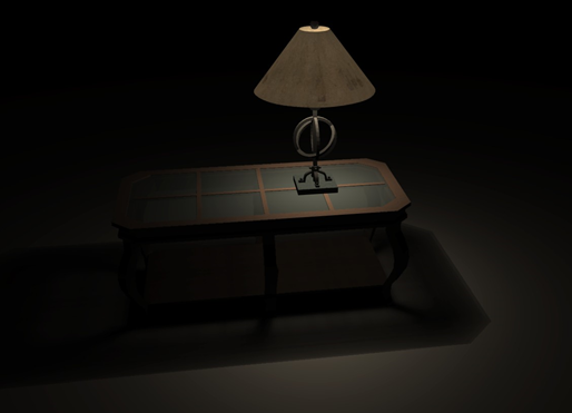
Table lamp based on Area light
Using Area light for interior lighting
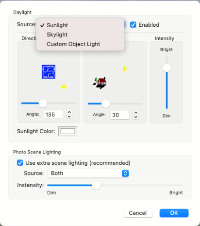
Daily Lighting Section
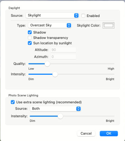
The ‘Daily Lighting’ section was added to the ‘Lighting’ property page.
Three options are available for setting the parameter. Source: Sunlight, Skylight, and Custom Object Light.
Skylight
This section allows to edit the set of Skylight parameters.

Parameters:
Type – Skylight type; ‘Overcast Sky’ by default
On – on/off Skylight; off by default
Shadow - on/off Skylight shadow; on by default
Shadow transparency - on/off Skylight shadow transparency; off by default
Sun location by Sunlight – if the option is on, then parameters ‘Direction’ and ‘Angle’ (from Sunlight property section) will be used to calculate the sun location, otherwise will be used parameters ‘Altitude’ and ‘Azimuth’; on by default
Altitude - sun altitude; a value between 0 and 90; 90 by default; enabled if option Sun location by Sunlight – is off
Azimuth - sun azimuth; a value between 0 and 360; 0 by default; enabled if option Sun location by Sunlight – is off
Quality - the quality of lighting and shadow; value between 0 and 1; 0.2 by default
Intensity - Skylight intensity; value between 0 and 1; 0.3 by default
Skylight Color - Skylight color; white by default
Custom Object Light
This section allows to edit the set of Custom Object Light parameters.
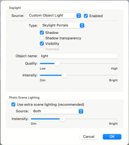
Parameters:
Type – type of light: Skylight Portals or Area Light; Skylight Portals by default
On – on/off light; on by default
Shadow - on/off light shadow; on by default
Shadow transparency - on/off light shadow transparency; off by default
Quality - the quality of lighting and shadow; a value between 0 and 1; 0.2 by default
Intensity - light intensity; value between 0 and 1; 0.3 by default
Visibility - on/off visibility of light’s geometry; on by default
Inverted - if the option is on, then the front side of the surface is used, backside otherwise; off by default; enabled if option Type is Area Light.
Use object with name - objects with this name will be used as a Custom Object Light; ‘light’ by default;
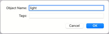
Local parameters of Custom Object Light
It is very important to set some parameters (for example, intensity) for each luminous object individually. This feature is implemented as a string in the parameter ‘Energy Efficiency Description’.
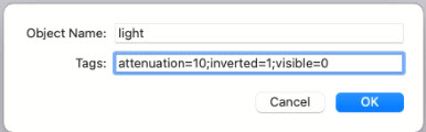
The format of the parameters is name=value. Parameters are separated by a semicolon. You can specify an incomplete set of parameters (for example, only one).
Currently implemented 3 parameters: attenuation, visible, inverted. If local parameters (visible and inverted) are specified, then they are used instead of global (local parameters take precedence over global).
Parameters:
attenuation – intensity attenuation coefficient (>=0); if the parameter is less than 1, an increase in intensity will occur.
visible – 0 or 1; if the parameter is 1 then light’s geometry is visible.
inverted – 0 or 1; if the parameter is 1, the front side of the surface is used, backside otherwise; can be used for Area Light only.
Using the Decorator Palette
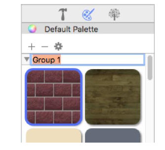
Punch! Decorator Palette allows you to construct lists of commonly used colors and materials so they can be easily used throughout your design. Each palette is divided into as many as 15 groups, allowing you to assign each group to a room or other segment of your design. You simply load the Decorator Palette with the colors and materials you want to apply to your 3D view, then save the palette for use in later sessions. When applying materials and colors, use the palettes you’ve created to establish an association between the palette and the surface in your design. If you want to change material or color, you can apply a new one to the palette and all of the surfaces where that content is applied are updated. Decorator Palettes can even be exported and imported for use in different drawings.
Note: A 3D view must be open to view the palettes
To build a palette
1 Open a 3D view window and, in the left sidebar, click the Decorator Palettes  button .
2 Drag a color or material from a content library into an empty palette space.
To apply colors and materials from the palette
■ Drag the color or material you want from the palette space to the surface in 3D. The selection appears in the 3D View.
To clear a palette entry
■ Right-click the entry you want to remove and choose Clear Palette Entry from the shortcut menu.
Identifying Colors and Materials from the Decorator Palette
When you’re working with a lot of different colors and materials, it can become difficult to remember the library they were applied from. You can find a color or material’s original library with just a couple of simple clicks.
To locate a color or material
■ Right-click the palette item and choose to Locate Item in Library from the shortcut menu. Its original library is displayed on the Content Pane.
Managing Decorator Palette Groups
You can organize the colors and materials of each room or region by assigning groups. The Decorator Palette provides you with 15 blank groups that you can fill and label.
To create a group
1 Drag the material or color you want into the palette. Repeat with additional materials or colors, as desired.
2 When you have all the materials and colors you want, right-click the group label you want to edit and choose Rename Group. The text becomes editable.
3 Enter the name of the group and press the Return key. The new name appears.
To expand or collapse a group
■ Click the disclosure triangle next to the group name that you want to expand or collapse.
(alternatively) Right-click the group label and choose to Expand All Groups or Collapse All Group
Managing Decorator Palettes
Your Decorator Palettes are saved separately from the rest of your design. That means you can use the same palette in different drawings, different sessions, or even share palettes with colleagues. When you have multiple decorator palettes, you can reorder them by dragging the palette name to a new position in the list.
To add a new palette
1 At the top of the Decorator Palette pane, click the Add  button and choose to Add a New Palette.
2 Type a name for the new palette and press the Return key.
To create a copy of a palette
1 At the top of the Decorator Palette pane, select the palette you want to copy.
2 Click the Add button and choose to Add a Copy.
3 Type a name for the new palette and press the Return key.
To delete a palette
1 At the top of the Decorator Palette pane, select the palette you want to remove.
2 Click the Remove button. A confirmation window appears.
3 Click Yes to delete the palette.
To import a custom palette
1 At the top of the Decorator Palette pane, click the Options  button and choose Import Palette. A dialog appears.
2 Find and select the palette you want to import and click Open. The palette appears in the Decorator Palette with the name “Imported Palette.”
(optional) To rename the palette, double-click the name and enter a new one, then press the Return key.
To export a palette
1 At the top of the Decorator Palette pane, select the palette you want to export.
2 Click the Options  button and choose Export. A dialog appears.
3 Enter a name for the palette in the Save As field and choose where you want to save the palette, then click Save.
Saving Custom 3D Views
You can save pre-set 3D views that can be easily accessed at any time. The Saved 3D Views menu option is available from the 3D menu. Here, you can save a 3D view and access your saved views. When you save a view, the rendering style is also saved with the view. Additionally, you can update a saved view and organize views to rename or delete them.
To save a 3D view
1 Set the 3D View with the direction, angle, and render style that you want to save.
2 Choose 3D > Saved 3D Views > Save 3D View. A dialog appears.
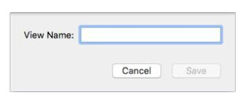
3 Enter a View Name in the field and click Save. The view is added to the Saved 3D Views submenu.
To access a saved view
■ Choose 3D > Saved 3D Views then choose the view you want from the submenu.
Organizing Saved 3D Views
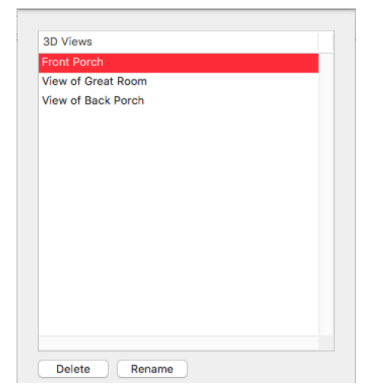
Using the 3D Views Organizer you can prioritize, rename, and deleting your saved 3D views.
To rename a saved 3D view
1 Choose 3D > Saved 3D Views > Organize 3D Views. A dialog appears.
2 Select the view you want to edit and click the Rename button then enter the name you want.
3 Click OK to close the dialog.
To delete a saved 3D view
1 Choose 3D > Saved 3D Views > Organize 3D Views. A dialog appears.
2 Select the view you want to edit and click the Delete button.
3 Click OK to close the dialog.
Customizing the Sun Position
Using the Sun Position and Lighting Assistant you can establish your site’s location, relative to the sun, virtually anywhere in the world. Then, adjust the lighting based on the month, day, even the hour. This ensures that your design will render with accurate sun angle and intensity any time, any day of the year. For example, if you want to see how shadows will look during the day while designing your landscape, or how the sunlight will look in a redesigned kitchen, you can use the Sun Position and Lighting Assistant to adjust the sunlight and see its effects in 3D.
Your Site Time and Location
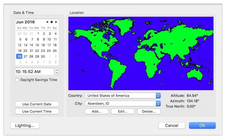
The position of the sun is determined based on the date, time, and location. When you choose the country and city for your location, the altitude and Azimuth coordinates are shown. You can even edit the details for existing locations or add a new location with detailed coordinates. When Daylight Savings Time is enabled, the time change is considered when positioning the sun.
To set the sun position to the current date and time
1 Open a 3D view and choose 3D > Sun Position and Lighting Assistant. A dialog appears.
2 Under Date & Time, click the Use Current Date button and then click the Use Current Time button.
(optional) Select the “Daylight Savings Time” checkbox.
3 Click OK.
To set the sun position to a specific date and time
1 Open a 3D view and choose 3D > Sun Position and Lighting Assistant. A dialog appears.
2 Under Date & Time, click the arrow buttons to choose the month you want and select the date in the calendar.
3 Enter the time of day you want or select the hour, minutes, or seconds and use the stepper controls to increase or decrease the selection.
(optional) Select the “Daylight Savings Time” checkbox.
4 Click OK.
To specify your location
1 Open a 3D view and choose 3D > Sun Position and Lighting Assistant. A dialog appears.
2 Under Location, choose the country you want from the Country pop-up menu.
3 Choose the city you want from the City pop-up menu.
4 Click OK.
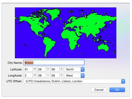
To add a location
1 Open a 3D view and choose 3D > Sun Position and Lighting Assistant. A dialog appears.
2 Choose the country in which you want to add a city.
3 Click the Add  button. A dialog appears.
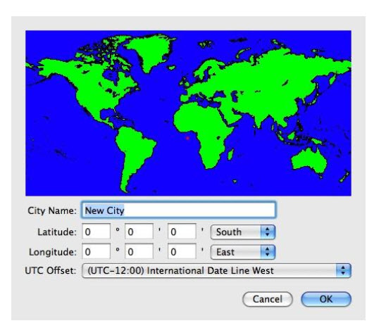
4 Enter the City Name in the corresponding field.
5 To specify the city’s location, click the map to set its coordinates.
(alternatively) Enter the city’s coordinates in the Latitude and Longitude fields. Be sure to choose North/South or East/West from the corresponding pop-up menu.
6 Choose the time zone from the UTC Offset pop-up menu.
7 Click OK.
To edit a location’s details
1 Open a 3D view and choose 3D > Sun Position and Lighting Assistant. A dialog appears.
2 Choose the country in which you want to edit a city from the Country pop-up menu.
3 Choose the city you want to edit from the City pop-up menu.
4 Click the Edit  button . A dialog appears.
5 Enter the City Name in the corresponding field.
6 To specify the city’s location, click the map to set its coordinates.
(alternatively) Enter the city’s coordinates in the Latitude and Longitude fields. Be sure to choose North/South or East/West from the corresponding pop-up menu.
7 Choose the time zone from the UTC Offset popup menu.
8 Click OK.
To delete a city
1 Open a 3D view and choose 3D > Sun Position and Lighting Assistant. A dialog appears.
2 Choose the country from which you want to delete a city from the Country pop-up menu.
3 Click the Delete  button. A dialog appears.
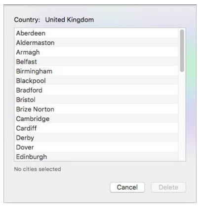
4 Select the city you want to delete. Hold down the Shift key, as you click, to select more than one city.
5 Click Delete and then click Delete again when asked to confirm the deletion.
6 Click OK.
Adjust Sun Lighting Settings
You can fine-tune the lighting settings so each hour is representative of your location at the time. Here you can control the amount of Scene Brightness, Shadow Contrast, and Shading Intensity to replicate the intensity of the sun and its effects at a particular time.
Note: To see the lighting changes in your current design, be sure the “Adjust your design’s lighting base on these values” checkbox is selected.
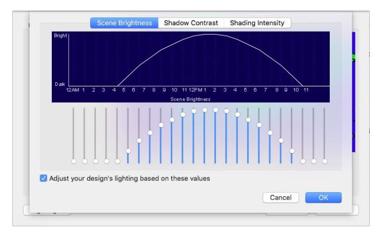
To adjust lighting settings
1 Open a 3D view and choose 3D > Sun Position and Lighting Assistant. A dialog appears.
2 Click the Lighting button and then choose the tab for the lighting you want to adjust.
3 Drag the sliders to adjust an hour’s brightness, contrast, or intensity.
(optional) Select the “Adjust your design’s lighting based on these values” checkbox to update your current drawing.
4 Click OK, then click OK again in the dialog that appears.
Preparing to Construct a RealModel
When constructing a RealModel, you’ll need to get a few supplies together first. Visit your local craft supply or hobby store to purchase these materials.
Items you’ll need to construct a RealModel:
■ Construction material — foam board or poster board
■ Adhesive — spray adhesive, rubber cement or glue stick, and so on
■ Tape
■ Straight pins
■ Straight-edge ruler
■ Artist’s knife or scalpel
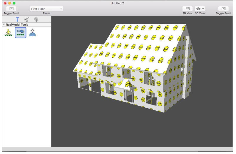
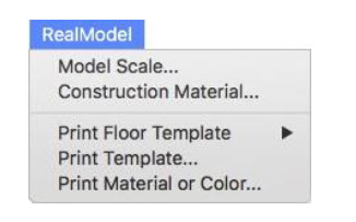
To open the RealModel view
■ Choose RealModel  from the 3D View pop-up menu. Your design appears in the RealModel View and the RealModel menu becomes available.
Defining Scale
The scale you choose defines the actual size of your model. All model templates print in this scale. For example, if you choose 1/2"=1', then a ten-foot wall prints as a five-inch template.
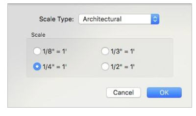
The following scale types are available:
Architectural offers an “X-inches-to-the-foot” scale (x representing a value).
Hobby offers standard gauge scale options.
Ratio offers a “1-to-X” scaling (x representing a value).
To select RealModel scale
1 Open the RealModel view and choose RealModel > Model Scale. A dialog appears.
2 Choose the Scale Type you want from the pop-up menu and select the Scale you want, and then click OK.
Printing RealModel Templates
The templates are used to guide you as you build your RealModel. They specify which wall section is attached to other walls and where doors and windows are placed. When printing your RealModel, you can print an entire floor at a time, or choose the particular template you want to print. For example, you could print all of the wall templates and assemble them, and then print all of the roof templates and assemble those. The printing options are available from the RealModel menu.
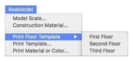
To print an entire floor
1 Choose RealModel > Print Floor Template and choose which floor you want to print.
2 In the dialog that appears, confirm your default printer selection, and other print settings, then click Print.
To print an entire template
1 Choose RealModel > Print Template. A dialog appears.
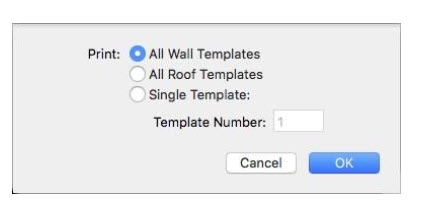
■ Print All Wall Templates Prints all of the walls in the design.
■ Print All Roof Templates Prints all of the roofs in the design.
■ Print Single Template Prints an individual template from your design. Enter the template number you want to print from the RealModel view.
2 Select the template you want and click OK.
3 In the dialog that appears, confirm your default printer selection, and other print settings, then click Print.
Printing Template Materials and Colors
To add a realistic look to your RealModel, you can print sheets of materials and colors to be applied to your model and trimmed to size. With this process, you can see what your design will look like. Follow these steps for every wall and roof on your model.
Note: It is best to print and assemble the material and color on each wall, before moving on to the next wall. If you choose not to do this, you should label each material template and color, as they are printed, to make identifying
them easier, when attaching them to your model.
To print template materials and colors
1 Decide which material you want to print first and then choose RealModel > Print Material or Color. A dialog appears.
2 Enter the template number of the material or color you want to print, then click OK. The Print dialog appears.
3 In the dialog that appears, confirm your default printer selection, and other print settings, then click Print.
Constructing Wall Templates
You will notice that some wall templates will have darker, shaded edges. These shaded areas indicate the thickness of your construction material. Use these as guidelines on where to attach adjoining walls. The directions for connecting the walls will be printed on each page. Be sure to transfer this information to the template, before cutting it out.
To construct a wall template
1 Attach each wall template to your construction material, using a permanent adhesive.
2 Cut out each wall section to the exact size of the template. Be sure to include shaded areas.
3 Attach each template to its appropriate counterpart.
Constructing Roof Templates
Although your roof templates may print attached at points, cut out each roof section separately from your construction material to the exact size of the template.
To construct a roof template
1 Attach each roof template to your construction material, using a permanent adhesive.
2 Cut out each roof section to the exact size of the template.
3 Attach each roof template to its appropriate counterpart.
4 Secure the roof to the walls.
Attaching Template Materials and Colors to Your Model
Once the materials and colors have been printed, you will need to affix them to the appropriate template and trim them to size. It is best to use spray adhesive, glue stick or tape for this step, as using white glue may cause the paper to wrinkle.
To attach the template materials and colors
1 Affix the material to the proper wall template, which has already been attached to the construction material.
2 Carefully trim around the outside edges of the wall template.
3 Cut out the door and window openings.
4 Attach each template to its appropriate counterpart.