Framing Plan Tab
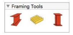
The tools contained on Punch! Home Design Software’s Framing Plan allows you to view and edit the structural elements of your design. You can add beams, joists, and other components, plus you have total control over what size lumber is used for what purpose. The Framing Tools are available in the left sidebar. For information on accessing the left sidebar, and controlling the display of the tools that appear, see “Left Sidebar”.

Adding Structural Components
The Framing Tools let you define exactly where and what kind of lumber or other material is to be used for the framing phase of your design.
Framing Beam
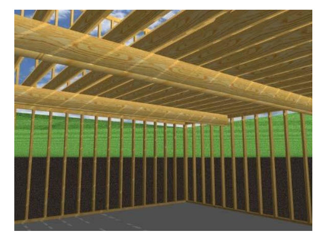
Framing beams are placed at a default elevation, which is the ceiling height plus the slab or joist thickness. You can edit the beam properties, including size and material, on the Properties pane in the right sidebar before or after you add it to your design. To see framing components in 3D, enabling the Framing rendering style. For more information, see “Accessing the 3D Rendering Styles”
To add a framing beam
1 Choose the Framing Bean  button from the Framing Tools group.
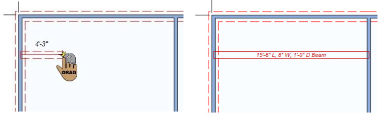
2 Use the Drag-to-Size drawing method to set the angle and length for the beam.
Framing Beam Properties
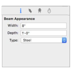
Framing beams are defined by their width, depth, and material. You can edit the properties before you draw or after the component has been added to your design by selecting it and clicking the Properties tab in the right sidebar.
Note: Always press Return to accept new values in a field.
Width defines the distance from one side of the beam to the other.
Depth defines the distance from the bottom of the beam to the top.
Type pop-up menu specifies the beam material type you want.
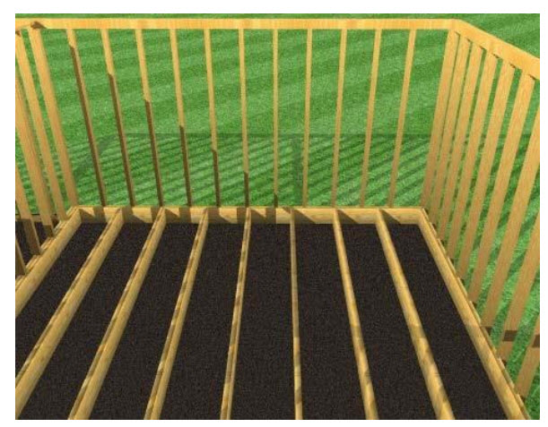
Floor Joist
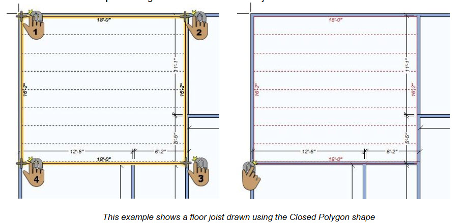
Floor joists are drawn using a polygon shape. You can edit the joist properties, including size and material, on the Properties pane in the right sidebar before or after you add it to your design. To see framing components in 3D, enabling the Framing rendering style. For more information, see “Accessing the 3D Rendering Styles”
To add flooring joists
1 Choose the Framing Joist button from the Framing Tools group.
2 On the Properties pane, choose how you want to draw the shape.
3 Use the Define 2D Shape drawing method to draw the floor joist section.
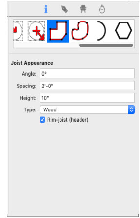
Joist Properties
Punch! Home Design Software automatically frames each floor, wall, and roof section with specifications that you can easily modify. Joists are defined by their angle, spacing, board width, and material. You can edit the properties before you draw or after the component has been added to your design by selecting it and clicking the Properties tab in the right sidebar.
Note: Always press Return to accept new values in a field.
Joist Angle defines the degree to which you want the joist boards placed.
Joist Spacing defines the distance between each joist (use feet-and-inches or just inches)
Joist Height defines the distance from the bottom of the board to the top.
Type pop-up menu specifies the joist material type you want.
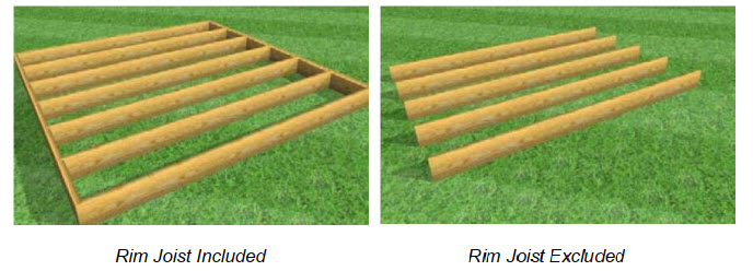
Rim-Joist(header) checkbox specifies whether headers should be included (selected) or excluded (deselected)
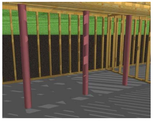
Framing Support Column
Support columns are placed at the base elevation of the current floor. You can edit the column properties, including size and material, on the Properties pane in the right sidebar before or after you add it to your design. To see framing components in 3D, enabling the Framing rendering style. For more information, see “Accessing the 3D Rendering Styles”
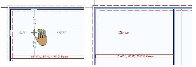
To place support columns
1 Choose the Framing Column  button from the Framing Tools group.
2 Use the Click Once to Place drawing method to place a column.
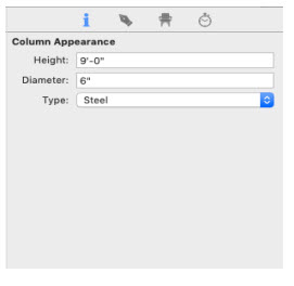
Support Column Properties
After adding a support column, you can change its material and size. You can edit the properties before you draw or after the component has been added to your design by selecting it and clicking the Properties tab on the right sidebar.
Note: Always press Return to accept new values in a field.
Height defines the distance from the bottom of the column to the top.
Diameter defines the distance from one side of the column to the other side.
Type pop-up menu specifies the column material type you want.
Customizing Wall Framing Properties
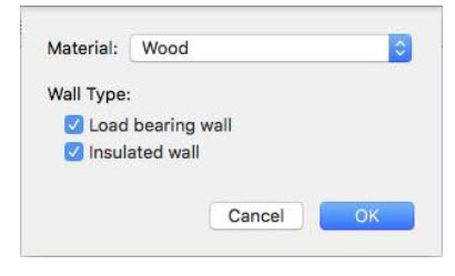
As you draw walls in Punch! Home Design Software you specify which walls are insulated, which are load-bearing, as well as the framing material used. You can specify these details in the Wall Framing dialog. To edit a wall’s framing properties, right-click the wall and choose Framing Properties. The Wall Framing dialog appears. After your edit, the settings, click OK to close the dialog.
Framing Material pop-up menu allows you to choose the material used for framing.
Load bearing wall checkbox specifies a wall as load-bearing when selected.
Insulated wall checkbox specifies a wall as insulted when selected.
Customizing Roof Framing Properties
Roof sections are automatically framed with specifications set in Punch! Home Design Software. You can easily modify all of these settings in the Roof Framing dialog. You can edit the framing properties for roofs created using the roof shape tools and the freehand roof tools; automatic roofs are controlled by the Automatic Roof Properties. For more information on automatic roof properties, see “Auto-Roof Properties”.
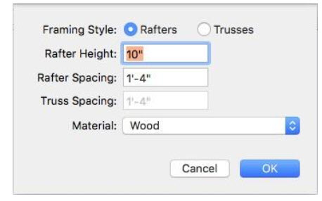
Framing Style specifies if roof framing uses rafters or trusses. Each has its own properties.
Rafter Height defines the distance from the bottom of the rafter board to the top when Rafters is selected.
Rafter Spacing defines the distance between each roof rafter when Rafters is selected.
Truss Spacing defines the distance between each roof truss when Trusses is selected.
Material pop-up menu allows you to choose the material used for framing.
To edit roof framing properties
1 Enable the Roof plan so the roof panels are visible in the design window.
2 Right-click the roof section and choose Framing Properties. A dialog appears.
3 Edit the settings as needed and then click OK.
Customizing Staircase Framing Properties
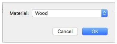
As you draw staircases in Punch! Home Design Software you specify the framing material in the Stair Framing dialog, which is accessible by right-clicking the staircase center line. The following option is available:
Framing Material options allow you to choose the material used for framing
To edit staircase framing properties
1 Right-click the staircase center line and choose Framing Properties. A dialog appears.
2 Choose the material you want from the pop-up menu and then click OK.
Customizing Deck Framing Properties
Decks are automatically framed with specifications set in Punch! Home Design Software. You can easily modify all of these settings.
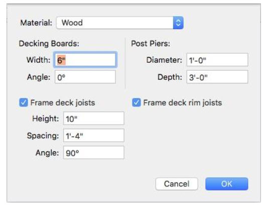
Material pop-up menu allows you to choose the material used for framing.
Decking Boards settings define the Width and Angle of the boards. Enter the values you want in the corresponding fields.
Frame deck joists checkbox specifies if joists are included (selected) on the top of the deck framing or excluded (deselected). When selected, you can define the height, spacing, and angle of the boards.
Post Piers settings define the diameter and depth (below ground) of the piers below each deck post. Enter the values you want in the corresponding fields.
Frame deck rim joists checkbox specifies if joists and rim-joists are included (selected) in the deck framing or excluded (deselected). When selected, you can define the size, spacing, and angle of the joists.
To edit deck framing properties
1 Enable the Deck plan so the deck is visible in the design window.
2 Right-click the deck and choose Framing Properties. A dialog appears.
3 Edit the settings and then click OK.
Customizing Foundation Framing Material
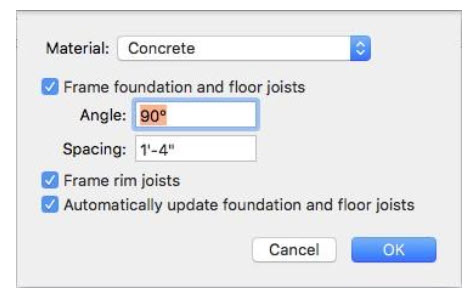
Structures are built with a concrete slab foundation by default. You can customize the foundation framing material to use concrete, steel, or wood. The foundation framing can be customized while working on any plan except the Foundation plan.
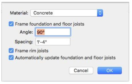
Material pop-up menu allows you to choose the material used for foundation framing.
Frame foundation and floor joists checkbox specifies if floor joists are included (selected) in the foundation framing or excluded (deselected). When selected, you can define the spacing and angle of the joists. (Only available with Wood and Steel). You can manually draw floor joists using the Floor Joist Tool (“Floor Joist”).
Frame rim joists checkbox specifies if headers should be included (selected) or excluded (deselected). (Only available with Wood and Steel).
Automatically update foundation framing checkbox controls if changes can be made to the foundation framing properties.
To edit foundation framing properties
1 Choose the Select Objects  button from the Editing Tools group then click to select the foundation perimeter. Its properties appear on the Properties pane.
2 Click the Framing Options button. A dialog appears.
3 Edit the settings and click OK.