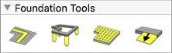
Foundation Plan Tab
Just like building in the real world, the best place to start is with a solid foundation. The Foundation Plan Tab includes tools to help you add the foundation details to your plan. You will also learn to add stiffener beams, draw piers, and define post-tension and slope. Most of the components added from the Foundation Plan tab are only visible in the 2D view.

Adding Stiffener Beams
Stiffener beams are used to support the foundation; typically, they run from one end of the foundation to the other. You can control the length, width, and dimension of each beam.
To place stiffener beams
1 Choose the Stiffener Beam  button from the Foundation Tools group. Its properties appear on the Properties pane.
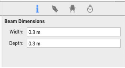
(optional) Click the Properties  tab in the right sidebar and enter the width and depth you want for the stiffener beam. Press the Return key to accept each value.
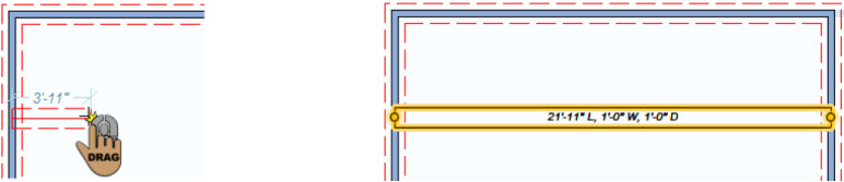
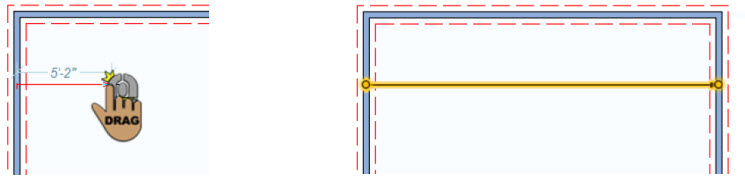
2 Use the Drag-to-Size drawing method to set the angle and length for the component.
Stiffener Beam Properties
Stiffener Beams are defined by their width and depth. Each of these properties can be increased up to 4'-2”. Since beams are only represented in the 2D view, you won’t see changes to the depth reflected in the design window. You can edit these values on the Properties pane while the tool is selected before you draw or by selecting a stiffener beam in your drawing.
Note: When editing values in a text field, be sure to press Return to accept changes.
Width defines the distance across the beam. Width runs perpendicular to the length.
Depth defines the distance from the top to the bottom of the stiffener beam. When viewing the stiffener beam in 2D, you are looking at a top view. If you are looking at the stiffener beam from the side, the depth runs from top to bottom.
Adding Foundation Piers
Foundation piers support the foundation. They are concrete pads that add strength under a support column. Even after you place piers, you can customize them. Foundation piers are visible in the 3D view when using the Framing render mode.
To add a foundation pier
1 Choose the Foundation Pier  button from the Foundation Tools group. Its properties appear on the Properties pane.
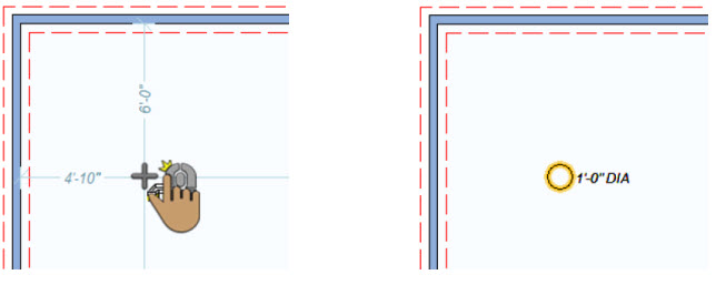
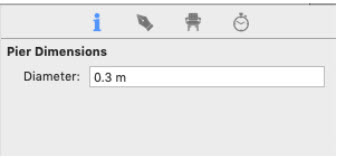
(optional) Click the Properties tab in the right sidebar and enter the diameter you want for the pier. Press the Return key to accept new values.
2 Use the Click Once to Place drawing method to place the component in your design.
Foundation Piers Properties
Foundation Piers are defined by their diameter. You can edit this value on the Properties pane while the tool is selected before you draw or by selecting a stiffener beam in your drawing.
Note: When editing values, always press Return to accept new values in a field.
Adding Post Tension Strands
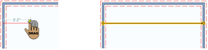
Post tension strands are used to prevent cracking in a concrete slab foundation. They extend from one edge of the foundation to the other and are bolted into the frame and set in concrete. Arrow indicates the direction in which the strands are stressed.
To place a post-tension strand
1 Choose the Post-Tension Strand  button from the Foundation Tools group.
2 Use the Drag-to-Size drawing method to set the angle and length for the component.
Adding Post Tension Strands
Post tension strands are used to prevent cracking in a concrete slab foundation. They extend from one edge of the foundation to the other and are bolted into the frame and set in concrete. Arrow indicates the direction in which the strands are stressed.
To place a post-tension strand
1 Choose the Post-Tension Strand  button from the Foundation Tools group.
2 Use the Drag-to-Size drawing method to set the angle and length for the component.
Drawing the Foundation Slope
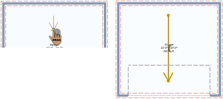
Foundation Slope is typically specified in garages or basement areas where there is a drain. It specifies which direction the floor area slopes.
To draw the foundation slope
1 Choose the Foundation Slope  button from the Foundation Tools group.
2 Use the Drag-to-Size drawing method to set the angle and length for the component.
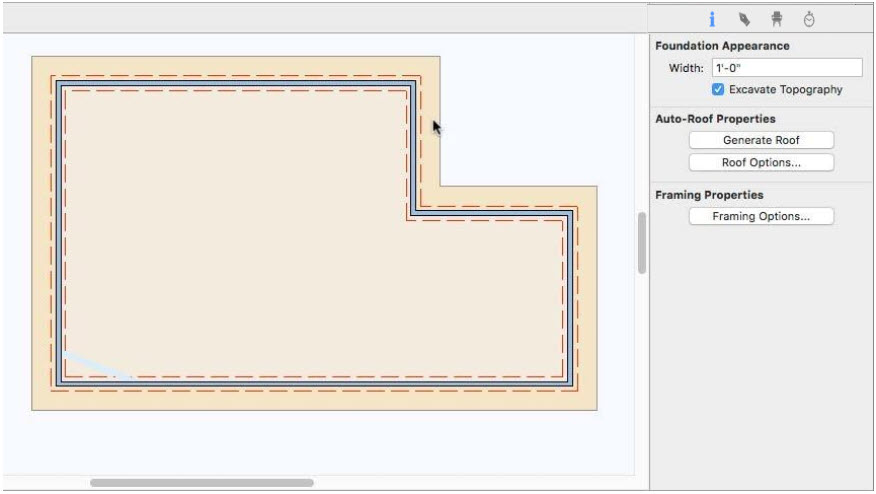
Setting Foundation Width
When the perimeter of an enclosure is selected, foundation appearance options become available on the Properties pane. The foundation is represented in the 2D view as the dotted red lines that run parallel along each side of the walls. As the foundation width changes, as does the distance between the dotted lines. The foundation is only displayed in the 2D view.
To define the foundation width
1 Choose the Select Objects  button from the Editing Tools group and click to select the foundation perimeter. Its properties appear on the Properties pane in the right sidebar.
2 Under Foundation Appearance, enter the foundation width you want and press the Return key.
To automatically excavate perimeters below grade
1 Choose the Select Objects  button from the Editing Tools group and click to select the foundation perimeter. Its properties appear on the Properties pane in the right sidebar.
2 Select the “Excavate Topography” checkbox to excavate the topography within the enclosure that is below grade. Deselect the “Excavate Topography” checkbox to keep the topography in place.